Toyota camry 2006 2011 2AZ FE starting hệ thống khởi động trên toyota camry 2AZ FE đời 2006 2011
Bạn đang xem bản rút gọn của tài liệu. Xem và tải ngay bản đầy đủ của tài liệu tại đây (1.46 MB, 16 trang )
2AZ-FE STARTING – STARTING SYSTEM
ST–1
ST
ENGINE2AZ-FE STARTING
STARTING SYSTEM
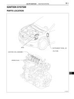
PARTS LOCATION
IGNITION SWITCH
STARTER
-STARTER RELAY
CLUTCH START SWITCH
PARK/NEUTRAL
POSITION SWITCH
MT:
ECM
AT:
ENGINE ROOM R/B
INSTRUMENT PANEL J/B
-AM1 FUSE
-ST/AM2 FUSE
-ALT FUSE
A135518E01
ST–2
2AZ-FE STARTING – STARTING SYSTEM
ST
SYSTEM DIAGRAM
ECM
A24
STA
48
4
L
B
P
N
C1
Park/Neutral
Position
Switch
A22
Clutch Start Switch
NSW
12
(*1) (*1)
(*2)
(*2)
(*2)
E23
Ignition Switch
ACC
IG1
ST1
IG2
ST2
AM1
AM2
3
7
4
5
AM1
ALT ST/AM2
FL MAIN
Battery
*1: M/T
*2: A/T
D1
C29 C3
(*1) (*2)
Starter
M
111
ST
1
5
2
3
C24
52
(*2)
A135060E01
2AZ-FE STARTING – STARTER
ST–3
ST
ENGINE2AZ-FE STARTING
STARTER
COMPONENTS
STARTER
ASSEMBLY
N*m (kgf*cm, ft.*lbf)
: Specified torque
9.8 (100, 87 in.*lbf)
37 (380, 28)
12 (120, 9)
for Manual Transaxle:
CLUTCH FLEXIBLE
HOSE BRACKET
x2
AIR CLEANER CAP SUB-ASSEMBLY
AIR CLEANER CASE
SUB-ASSEMBLY
AIR CLEANER
INLET ASSEMBLY
AIR CLEANER FILTER ELEMENT
5.0 (51, 44 in.*lbf)
x3
5.0 (51, 44 in.*lbf)
A133564E01
ST–4
2AZ-FE STARTING – STARTER
ST
PLANETARY GEAR
REPAIR SERVICE
STARTER KIT
STARTER ARMATURE ASSEMBLY
STARTER ARMATURE PLATE
STARTER YOKE ASSEMBLY
STARTER COMMUTATOR END FRAME ASSEMBLY
Apply High-temperature grease
N*m (kgf*cm, ft.*lbf)
: Specified torque
Non-reusable part
6.0 (61, 53 in.*lbf)
WASHER
SNAP RING
6.0 (61, 53 in.*lbf)
-PLUNGER
-RETURN SPRING
-MAGNETIC SWITCH
7.5 (76, 66 in.*lbf)
10 (102, 7)
STARTER COMMUTATOR
END FRAME COVER
MOTOR TERMINAL STARTER KIT
A134900E01
2AZ-FE STARTING – STARTER
ST–5
ST
REMOVAL
1. DISCONNECT CABLE FROM NEGATIVE BATTERY
TERMINAL
2. REMOVE AIR CLEANER INLET ASSEMBLY (See
page EM-94)
3. REMOVE AIR CLEANER CAP SUB-ASSEMBLY (See
page ES-416)
4. REMOVE AIR CLEANER CASE SUB-ASSEMBLY (See
page EM-95)
5. REMOVE STARTER ASSEMBLY (for Manual
Transaxle)
(a) Disconnect the terminal 50 connector from the
starter assembly.
(b) Remove the nut and disconnect the wire harness
from terminal 30.
(c) Remove the 3 bolts, clutch flexible hose bracket and
starter assembly.
6. REMOVE STARTER ASSEMBLY (for Automatic
Transaxle)
(a) Disconnect the terminal 50 connector from the
starter assembly.
(b) Remove the nut and disconnect the wire harness
from terminal 30.
(c) Remove the 2 bolts and starter assembly.
A133565
Bracket
A133566E01
A134876
A134877
ST–6
2AZ-FE STARTING – STARTER
ST
DISASSEMBLY
1. REMOVE REPAIR SERVICE STARTER KIT
(a) Remove the nut and disconnect the lead wire from
terminal C.
(b) Remove the 2 screws that hold the magnetic switch
to the motor terminal starter kit.
(c) Remove the repair service starter kit.
(d) Remove the return spring and the plunger from the
repair service starter kit.
2. REMOVE STARTER YOKE ASSEMBLY
(a) Remove the 2 through bolts and pull out the starter
yoke assembly together with the starter commutator
end frame assembly.
(b) Remove the starter yoke assembly from the starter
commutator end frame assembly.
3. REMOVE STARTER ARMATURE PLATE
(a) Remove the starter armature plate from the starter
yoke assembly.
A079718E05
A079719E05
A079720E05
A079721E03
A079722E04
2AZ-FE STARTING – STARTER
ST–7
ST
4. REMOVE STARTER COMMUTATOR END FRAME
COVER
(a) Using a screwdriver, remove the starter commutator
end frame cover.
5. REMOVE STARTER ARMATURE ASSEMBLY
(a) Using snap ring pliers, remove the snap ring and
plate washer.
(b) Remove the starter armature assembly from the
commutator end frame assembly.
6. REMOVE PLANETARY GEAR
(a) Remove the 3 planetary gears from the motor
terminal starter kit.
A079723E03
Snap Ring Pliers
A082440E07
A081167E03
ST–8
2AZ-FE STARTING – STARTER
ST
INSPECTION
1. INSPECT STARTER ASSEMBLY
CAUTION:
Make sure to complete each of the following tests
within 5 seconds to prevent the coil from burning
out.
(a) Perform pull-in test:
(1) Disconnect the lead wire from terminal C.
(2) Connect the battery to the magnetic switch as
shown in the illustration. Check that the clutch
pinion gear moves outward.
If the clutch pinion gear does not move
outward, replace the repair service starter kit.
(b) Perform hold-in test:
(1) Disconnect the negative (-) terminal lead from
terminal C under the conditions for pull-in test.
Check that the pinion gear remains out.
If the clutch pinion gear moves inward, replace
the repair service starter kit.
(c) Inspect clutch pinion gear return:
(1) Disconnect the negative (-) lead from the
starter body. Check that the clutch pinion gear
moves inward.
If the clutch pinion gear does not move inward,
replace the repair service starter kit.
(d) Perform no-load performance test:
(1) Connect the field coil wire to terminal C with the
nut. Make sure that the lead is not grounded.
Torque: 10 N*m (102 kgf*cm, 7 ft.*lbf)
(2) Clamp the starter in a vise.
Terminal C
A133511E01
Terminal C
Terminal 50
Body
A133512E01
Body
Terminal C
Terminal 50
A133513E01
Body
Terminal C
Terminal 50
A133514E01
2AZ-FE STARTING – STARTER
ST–9
ST
(3) Connect the battery and an ammeter to the
starter as shown in the illustration.
(4) Check that the starter rotates smoothly and
steadily with the clutch pinion gear extended.
Check that the ammeter reads the specified
current.
Specified current
If the result is not as specified, overhaul the
starter assembly.
2. INSPECT REPAIR SERVICE STARTER KIT
(a) Check the plunger.
(1) Push in the plunger and check that it returns
quickly to its original position.
If necessary, replace the repair service starter
kit.
(b) Inspect the resistance of the pull-in coil.
(1) Using an ohmmeter, measure the resistance
between terminals 50 and C.
Standard resistance
If the resistance is not as specified, replace the
repair service starter kit.
(c) Inspect the resistance of the hold-in coil.
(1) Using an ohmmeter, measure the resistance
between terminal 50 and the switch body.
Standard resistance
If the resistance is not as specified, replace the
repair service starter kit.
3. INSPECT STARTER ARMATURE ASSEMBLY
(a) Check the commutator surface for dirt or burning.
If the surface is dirty or burnt, smooth the surface
with 400-grit sandpaper or leather.
Body
Ammeter
Terminal 50
Terminal 30
A133510E01
Condition Specified condition
at 11.5 V 90 A or less
A058586E04
Terminal C
Below 1 Ω
Terminal 50
A079725E08
Tester connection Specified condition
Terminal 50 - Terminal C Below 1 Ω
Terminal 50
Below 2 Ω
Body
A079726E07
Tester connection Specified condition
Terminal 50 - Switch body Below 2 Ω
ST–10
2AZ-FE STARTING – STARTER
ST
(b) Inspect the resistance of the commutator.
(1) Using an ohmmeter, measure the resistance
between the segments of the commutator.
Standard resistance
If the resistance is not as specified, replace the
starter armature assembly.
(2) Using an ohmmeter, measure the resistance
between the commutator and armature coil
core.
Standard resistance
If the resistance is not as specified, replace the
starter armature assembly.
(c) Using vernier calipers, measure the commutator
depth.
Specified depth:
3.1 mm (0.122 in.)
Maximum depth:
3.8 mm (0.150 in.)
If the depth is greater than the maximum, replace
the starter armature assembly.
4. INSPECT STARTER COMMUTATOR END FRAME
ASSEMBLY
(a) Check the brush length.
(1) Using vernier calipers, measure the brush
length.
Specified length:
9.0 mm (0.354 in.)
Maximum length:
4.0 mm (0.157 in.)
If the length is less than the minimum, replace
the starter commutator end frame assembly.
(b) Check the resistance.
(1) Using an ohmmeter, measure the resistance
between the positive (+) and negative (-)
brushes.
Resistance:
10 kΩ or higher
If the resistance is not as specified, repair or
replace the starter commutator end frame
assembly.
Below 1 Ω
Segment
A058372E04
Tester connection Specified condition
Segment - Segment Below 1 Ω
Commutator
Coil Core
10 kΩ or Higher
A058373E04
Tester connection Specified condition
Commutator - Armature coil core 10 kΩ or higher
Depth
A058584E09
Length
A076677E10
10 kΩ or Higher
A079766E10
2AZ-FE STARTING – STARTER
ST–11
ST
5. INSPECT MOTOR TERMINAL STARTER KIT
(a) Check the starter clutch.
(1) Rotate the clutch pinion gear counterclockwise
and check that it turns freely. Try to rotate the
clutch pinion gear clockwise and check that it
locks.
If necessary, replace the motor terminal starter
kit.
REASSEMBLY
1. INSTALL PLANETARY GEAR
(a) Apply high-temperature grease to the planetary
gears and pin parts of the planetary shaft.
(b) Install the 3 planetary gears to the motor terminal
starter kit.
2. INSTALL STARTER ARMATURE ASSEMBLY
(a) Apply high-temperature grease to the plate washer
and the armature shaft.
(b) Install the starter armature assembly to the starter
commutator end frame assembly.
(c) Using snap ring pliers, install the plate washer and a
new snap ring.
(d) Using vernier calipers, measure the snap ring.
Maximum length:
5.0 mm (0.197 in.)
If the length is greater than the maximum, replace
the snap ring with a new one.
3. INSTALL STARTER COMMUTATOR END FRAME
COVER
(a) Install the starter commutator end frame cover to
the starter commutator end frame assembly.
Lock
Free
A081655E05
Apply Grease
A081656E06
Snap Ring Pliers
A082440E08
Length
A058810E14
A081178E03
ST–12
2AZ-FE STARTING – STARTER
ST
4. INSTALL STARTER ARMATURE PLATE
(a) Align the claw of the armature plate with the groove
inside the starter yoke assembly, and install the
starter armature plate.
5. INSTALL STARTER COMMUTATOR END FRAME
ASSEMBLY
(a) Align the starter commutator end frame rubber with
the groove of the starter yoke assembly.
(b) Install the starter commutator end frame assembly
to the starter yoke assembly.
NOTICE:
The magnet of the starter yoke assembly may
attract the starter armature assembly when the
starter commutator end frame assembly is
installed, causing the magnet to break.
6. INSTALL STARTER YOKE ASSEMBLY
(a) Align the claw of the starter yoke with the groove
inside the motor terminal starter kit.
(b) Install the starter yoke with the 2 through bolts.
Torque: 6.0 N*m (61 kgf*cm, 53 in.*lbf)
7. INSTALL REPAIR SERVICE STARTER KIT
(a) Apply high-temperature grease to the plunger and
the hook.
(b) Hang the plunger hook of the repair service starter
kit to the drive lever hook.
(c) Install the plunger and the return spring.
Groove
Claw
A073991E14
Rubber
Groove
A079727E08
Groove
Claw
A079728E07
A079720E06
A079729E03
2AZ-FE STARTING – STARTER
ST–13
ST
(d) Install the repair service starter kit with the 2 screws.
Torque: 7.5 N*m (76 kgf*cm, 66 in.*lbf)
(e) Connect the lead wire to terminal C with the nut.
Torque: 10 N*m (102 kgf*cm, 7 ft.*lbf)
INSTALLATION
1. INSTALL STARTER ASSEMBLY (for Manual
Transaxle)
(a) Install the starter assembly and clutch flexible hose
bracket with the 3 bolts.
Torque: Bolt A
37 N*m (380 kgf*cm, 28 ft.*lbf)
Bolt B
12 N*m (120 kgf*cm, 9 ft.*lbf)
(b) Connect the wire harness to terminal 30 and install
the nut. Then, attach the terminal cap.
Torque: 9.8 N*m (100 kgf*cm, 87 in.*lbf)
(c) Connect the terminal 50 connector to the starter
assembly.
2. INSTALL STARTER ASSEMBLY (for Automatic
Transaxle)
(a) Install the starter assembly with the 2 bolts.
Torque: 37 N*m (380 kgf*cm, 28 ft.*lbf)
A079719E06
A079718E06
Bracket
A
A
B
A133566E02
A133565
A134877
ST–14
2AZ-FE STARTING – STARTER
ST
(b) Connect the wire harness to terminal 30 and install
the nut. Then, attach the terminal cap.
Torque: 9.8 N*m (100 kgf*cm, 87 in.*lbf)
(c) Connect the terminal 50 connector to the starter
assembly.
3. INSTALL AIR CLEANER CASE SUB-ASSEMBLY (See
page EM-120)
4. INSTALL AIR CLEANER CAP SUB-ASSEMBLY (See
page ES-419)
5. INSTALL AIR CLEANER INLET ASSEMBLY (See page
EM-120)
6. CONNECT CABLE TO NEGATIVE BATTERY
TERMINAL (See page EM-120)
A134876
ST–14
2AZ-FE STARTING – STARTER RELAY
ST
STARTER RELAY
ON-VEHICLE INSPECTION
1. INSPECT STARTER RELAY ASSEMBLY
(a) Using an ohmmeter, measure the resistance
between each terminal.
Standard resistance
If the result is not as specified, replace the starter
relay assembly.
E034090E03
Tester Connection Specified Condition
3 - 5
10 kΩ or higher
Below 1 Ω (when battery voltage is
applied to terminals 1 and 2)
2AZ-FE STARTING – IGNITION SWITCH
ST–15
ST
IGNITION SWITCH
ON-VEHICLE INSPECTION
1. INSPECT IGNITION OR STARTER SWITCH
ASSEMBLY
(a) Check the resistance.
(1) Using an ohmmeter, measure the resistance
between the terminals.
Standard resistance
If the result is not as specified, replace the
ignition or starter switch.
1
56
234
7
LOCK
ACC
ON
START
AM1 ACC IG1ST1
AM2IG2ST2
A119190E04
Condition Tester Connection Specified Condition
LOCK Between all terminals 10 kΩ or higher
ACC 2 - 4 Below 1 Ω
ON
1 - 2 - 4
Below 1 Ω
5 - 6
START
1 - 3 - 4
Below 1 Ω
5 - 6 - 7