Toyota camry 2006 2011 audio visual hệ thống radio trên toyota camry đời 2006 2011
Bạn đang xem bản rút gọn của tài liệu. Xem và tải ngay bản đầy đủ của tài liệu tại đây (8.22 MB, 236 trang )
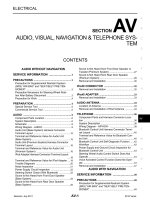
AUDIO / VISUAL – AUDIO AND VISUAL SYSTEM
AV–1
AV
BODY ELECTRICALAUDIO / VISUAL
AUDIO AND VISUAL SYSTEM
PARTS LOCATION
COMBINATION METER
ENGINE ROOM R/B AND J/B
STEREO COMPONENT AMPLIFIER (*1)
MICROPHONE
ANTENNA
AMPLIFIER
ANTENNA
INSTRUMENT PANEL J/B
RADIO RECEIVER
STEREO JACK ADAPTER
*1: for Premium Model
SPIRAL CABLE
STEERING PAD SWITCH
REAR SIDE SPEAKER
FRONT SIDE SPEAKER
FRONT SIDE SPEAKER
FRONT SIDE SPEAKER
-FRONT NO. 2 SPEAKER LH
-REAR SPEAKER
-FRONT NO. 2 SPEAKER RH
-FRONT NO. 1 SPEAKER
-RADIO NO. 1 FUSE
-AMP FUSE
-PANEL FUSE
-RADIO NO. 2 FUSE
-ACC RELAY
-TAIL RELAY
E132132E02
AV–2
AUDIO / VISUAL – AUDIO AND VISUAL SYSTEM
AV
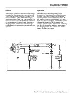
SYSTEM DIAGRAM
Standard Model:
Steering Pad Switch Combination Meter
Speed Signal
Sound Signal
Speakers
Sound Signal
Switch Signal
Spiral Cable
Antenna
Antenna
Amplifier
Stereo Jack Adapter
Radio Receiver
E129797E03
AUDIO / VISUAL – AUDIO AND VISUAL SYSTEM
AV–3
AV
Premium Model:
Steering Pad Switch Combination Meter
(Slave Unit)
Speed Signal
Sound Signal
Speakers
Sound SignalMicrophone
Voice Signal
: AVC-LAN
Switch Signal
Spiral Cable
Antenna
Antenna
Amplifier
Stereo Component
Amplifier
Stereo Jack AdapterMicrophone
Assembly
Radio Receiver
(Master Unit)
E129796E02
AV–4
AUDIO / VISUAL – AUDIO AND VISUAL SYSTEM
AV
SYSTEM DESCRIPTION
1. DISC PLAYER OUTLINE
(a) A CD player uses a laser pickup to read digital
signals recorded on CDs. By converting the digital
signals to analog, music and other content can be
played.
CAUTION:
Do not look directly at the laser pickup because
the CD player uses an invisible laser beam. Be
sure to operate the player only as instructed.
NOTICE:
• Do not disassemble any part of the CD player.
• Do not apply oil to the CD player.
• Do not insert anything but a CD into the CD
player.
(b) Usable discs
(1) The CD player can only play audio CDs, CD-Rs
(CD-Recordable), and CD-RWs (CD-
ReWritable) that have any of the following
marks:
(c) Precautions for use of discs
NOTICE:
• Copy-protected CDs cannot be played.
• CD-Rs and CD-RWs may not be played
depending on the recording conditions or
characteristics of the discs, or due to
damage, dirt, or deterioration caused by
leaving the discs in the cabin for a long time.
• Unfinalized CD-Rs and CD-RWs cannot be
played.
• Keep the discs away from dirt. Be careful not
to damage the discs or leave your
fingerprints on them.
• Hold discs by the outer edge and center hole
with the label side up.
• Leaving the disc exposed halfway out of the
slot for a long time after pressing the disc
eject button may cause deformation of the
disc, making the disc unusable.
• If discs have adhesive tape, stickers, CDR
labels, or any traces of such labels attached,
the discs may not be ejected or player
malfunctions may result.
E119759
AUDIO / VISUAL – AUDIO AND VISUAL SYSTEM
AV–5
AV
• Keep the discs away from direct sunlight.
(Exposure to direct sunlight may cause
deformation of the disc, making the disc
unusable.)
• Do not use odd-shaped CDs because these
may cause player malfunctions.
• Do not use discs whose recording portion is
transparent or translucent because they may
not be inserted, ejected, or played normally.
HINT:
• When it is cold or it is raining, if the windows mist
up, mist and also dew may form in the player. In
such a case, the CD may skip or the CD may
stop in the middle of play. Ventilate or dehumidify
the cabin for a while before using the player.
• The CD may skip if the player experiences strong
vibrations when the vehicle is driven on rough
road or similar uneven surface(s).
(d) Cleaning
NOTICE:
Do not use a lens cleaner because it may cause
a malfunction in the pickup portion of the player.
(1) If dirt is on the disc surface, wipe it clean with a
soft dry cloth such as an eyeglass cleaner for
plastic lenses from the inside to the outside in a
radial direction.
NOTICE:
• Pressing on the disc by hand or rubbing
the disc with a hard cloth may scratch the
disc surface.
• Use of solvent such as a record spray,
antistatic agent, alcohol, benzine, and
thinner, or a chemical cloth may cause
damage to the disc, making the disc
unusable.
2. MP3/WMA OUTLINE
(a) Playable MP3 file standards
(b) Playable WMA file standards
I100151
Compatible standard MP3 (MPEG1 LAYER3, MPEG2 LSF LAYER 3)
Compatible sampling frequency
• MPEG1 LAYER3: 32, 44.1, 48 (kHz)
• MPEG2 LSF LAYER3: 16, 22.05, 24 (kHz)
Compatible bit rate
• MPEG1 LAYER3: 64, 80, 96, 112, 128, 160, 192, 224, 256, 320
(kbps)
• MPEG2 LSF LAYER3: 64, 80, 96, 112, 128, 144, 160 (kbps)
• Compatible with VBR
Compatible channel mode Stereo, joint stereo, dual channel, monaural
Compatible standard WMA Ver. 7, 8, and 9
Compatible sampling frequency 32, 44.1, 48 (kHz)
Compatible bit rate
• Ver. 7, 8: CBR48, 64, 80, 96, 128, 160, 192 (kbps)
• Ver. 9: CBR48, 64, 80, 96, 128, 160, 192, 256, 320 (kbps)
• Compatible with playback of channel 2 only
AV–6
AUDIO / VISUAL – AUDIO AND VISUAL SYSTEM
AV
(c) ID3 tag and WMA tag
(1) Additional textual information called ID3 tag can
be input to MP3 files. Information such as song
titles and artist names can be stored.
HINT:
This player is compatible with the ID3 tags of ID3
Ver. 1.0 and 1.1, and ID3 Ver. 2.2 and 2.3.
(Number of characters complies with ID3 Ver.
1.0 and 1.1.)
(2) Additional textual information called WMA tag
can be input to WMA files. Information such as
song titles and artist names can be stored.
(d) Usable media
(1) Only CD-ROMs, CD-Rs (CD-Recordable), and
CD-RWs (CD-ReWritable) can be used to play
MP3/WMA files.
NOTICE:
• CD-Rs and CD-RWs are more easily
affected by a hot and humid environment
than discs used for normal audio CDs. For
this reason, some CD-Rs and CD-RWs
may not be played.
• If there are fingerprints or scratches on
the disc, the disc may not be played or the
CD may skip.
• Some CD-Rs and CD-RWs deteriorate if
they are left in the cabin for a long time.
• Keep CD-Rs and CD-RWs in a storage
case that is impenetrable to light.
(e) Usable media format
(1) Usable media format
HINT:
• As for MP3/WMA files written in any format
other than those above, the contents of the
files may not be played normally or the file
names or folder names may not be displayed
correctly.
• This player is compatible with multi-session
discs and can play CD-Rs and CD-RWs on
which MP3/WMA files are added. However,
only the first session can be played.
• Discs whose first session includes both music
data and MP3 or WMA format data cannot be
played.
(2) Standard and restrictions
Disc format CD-ROM Mode 1, CD-ROM XA Mode 2 Form1
File format ISO9660 Level 1 and Level 2 (Joliet, Romeo)
Maximum directory levels 8 levels
Maximum number of characters for a folder name/file name 32 characters
Maximum number of folders
192 (Including empty folders, route folders, and folders that do not
contain MP3/WMA files)
Maximum number of files in a disc 255 (Including non-MP3/WMA files)
AUDIO / VISUAL – AUDIO AND VISUAL SYSTEM
AV–7
AV
(f) File names
(1) Only files with an extension of ".mp3" or ".wma"
can be recognized and played as MP3 or WMA
files.
(2) Save MP3 or WMA files with an extension of
".mp3" or ".wma".
NOTICE:
If saving non-MP3 or non-WMA files with an
extension of ".mp3" or ".wma", those files
are wrongly recognized as MP3 or WMA files
and played. A loud noise may occur and
damage to the speaker may result.
3. AVC-LAN DESCRIPTION
(a) What is AVC-LAN?
AVC-LAN, an abbreviation for "Audio Visual
Communication Local Area Network", is a united
standard developed by the manufacturers in
affiliation with Toyota Motor Corporation. This
standard pertains to audio and visual signals as well
as switch and communication signals.
(b) Purpose:
Recently, car audio systems have rapidly developed
and the functions have vastly changed. The
conventional car audio system is being integrated
with multi-media interfaces similar to those in
navigation systems. At the same time, customers
are demanding higher quality from their audio
systems. This is merely an overview of the
standardization background. The specific purposes
are as follows:
(1) To solve sound problems, etc. caused by using
components of different manufacturers through
signal standardization.
(2) To allow each manufacturer to concentrate on
developing products they do best. From this,
reasonably priced products can be produced.
HINT:
• If a short to +B or short to ground is detected
in the AVC-LAN circuit, communication is
interrupted and the audio system will stop
functioning.
Radio Receiver
(Resistor 60 to 80 Ω)
AVC-LAN
Stereo Component Amplifier
Example:
I100319E09
AV–8
AUDIO / VISUAL – AUDIO AND VISUAL SYSTEM
AV
• If the audio system has a navigation system
installed, the multi-display unit acts as the
master unit. If the navigation system is not
installed, the audio head unit acts as the
master unit instead. If the radio and
navigation assembly is installed, it is the
master unit.
• The radio receiver contains a resistor that is
necessary to enable communication on the
different AVC-LAN circuits.
• The car audio system with an AVC-LAN
circuit has a diagnostic function.
• Each component has a specified number (3-
digit) called a physical address. Each function
has a number (2-digit) called a logical
address.
4. COMMUNICATION SYSTEM OUTLINE
(a) Components of the audio system communicate with
each other via the AVC-LAN.
(b) The master component of the AVC-LAN is a radio
receiver with a 60 to 80 Ω resistor. This is essential
for communication.
(c) If a short circuit or open circuit occurs in the AVC-
LAN circuit, communication is interrupted and the
audio system will stop functioning.
5. DIAGNOSTIC FUNCTION OUTLINE
(a) The audio system has a diagnostic function (the
result is indicated on the master unit).
(b) A 3-digit hexadecimal component code (physical
address) is allocated to each component on the
AVC-LAN. Using this code, the component in the
diagnostic function can be displayed.
6. "BLUETOOTH" OUTLINE
(a) "Bluetooth" is a trademark owned by Bluetooth SIG.
Inc.
E100921
AUDIO / VISUAL – AUDIO AND VISUAL SYSTEM
AV–9
AV
(b) "Bluetooth" is a new wireless connection technology
that uses the 2.4 GHz frequency band. This makes
it possible to connect a cellular phone ("Bluetooth"
compatible phone
*1
) to the radio receiver (the
"Bluetooth" system is built in), and use the
handsfree function of the cellular phone, even if it is
in a pocket or bag. As a result, it is not necessary to
use a connector attached directly to the cellular
phone.
*1
: Some versions of "Bluetooth" compatible cellular
phones may not function.
HINT:
The communication performance of "Bluetooth"
may vary depending on obstructions or radio wave
conditions between communication devices,
electromagnetic radiation, communication device
sensitivity, or antenna capacity.
Example:
Radio Receiver
(Built-in “Bluetooth” receiver antenna)
Cellular Phone (”Bluetooth” type)
Cellular Tower
E129829E02
AV–10
AUDIO / VISUAL – AUDIO AND VISUAL SYSTEM
AV
HOW TO PROCEED WITH
TROUBLESHOOTING
NEXT
Standard voltage:
11 to 14 V
If the voltage is below 11 V, recharge or replace the battery
before proceeding.
NEXT
(a) Turn the ignition switch on (IG).
(b) Check whether or not the radio receiver turns on.
Result
B
A
(a) Check for DTCs and note any codes that are output.
(b) Delete the DTCs.
(c) Recheck for DTCs by simulating the operation indicated
by the DTCs.
HINT:
• If the system cannot enter the diagnostic mode,
inspect the AVC-LAN and all the components that
connect to the AVC-LAN for short circuits and repair
or replace the problem part.
• Even if the malfunction symptom is not confirmed,
check the DTCs. This is because the system stores
past DTCs.
• Check and clear past DTCs. Then check for DTCs.
Result
1
VEHICLE BROUGHT TO WORKSHOP
2
INSPECT BATTERY VOLTAGE
3
BASIC INSPECTION
Result Proceed to
Radio receiver turns on A
Radio receiver does not turn on B
Go to step 6
4
CHECK FOR DTC
Result Proceed to
DTC is output again A
DTC is not output B
AUDIO / VISUAL – AUDIO AND VISUAL SYSTEM
AV–11
AV
B
A
Find the output code in the diagnostic trouble code chart (See
page AV-27).
NEXT
Refer to the problem symptoms table (See page AV-13).
Result
B
A
(a) Terminals of ECU (See page AV-15).
NEXT
NEXT
NEXT
Go to step 6
5
DIAGNOSTIC TROUBLE CODE CHART
Go to step 8
6
PROBLEM SYMPTOMS TABLE
Result Proceed to
Fault is not listed in problem symptoms table A
Fault is listed in problem symptoms table B
Go to step 8
7
OVERALL ANALYSIS AND TROUBLESHOOTING
8
ADJUST, REPAIR OR REPLACE
9
CONFIRMATION TEST
END
AV–12
AUDIO / VISUAL – AUDIO AND VISUAL SYSTEM
AV
IDENTIFICATION OF NOISE SOURCE
1. Radio Description
(a) Radio frequency band
(1) Radio broadcasts use the radio frequency bands
shown in the table below.
(b) Service area
(1) The service areas of AM and FM broadcasts are
vastly different. Sometimes an AM broadcast
can be received very clearly but an FM stereo
cannot. FM stereo has the smallest service area,
and is prone to pick up static and other types of
interference such as noise.
(c) Radio reception problems
HINT:
In addition to static, other problems such as
"phasing", "multipath", and "fade out" exist. These
problems are not caused by electrical noise, but by
the radio signal propagation method itself.
(1) Phasing
AM broadcasts are susceptible to electrical
interference and another kind of interference
called phasing. Occurring only at night, phasing
is the interference created when a vehicle
receives 2 radio wave signals from the same
transmitter. One signal is reflected off the
ionosphere and the other signal is received
directly from the transmitter.
Frequency
30 kHz
30 MHz
30 MHz
300 kHz
300 MHz
Designation
Radio Wave
Modulation
LF
MF
HF
VHF
AM
FM
Frequency modulation
Amplitude modulation
LF: Low Frequency
VHF: Very High Frequency
HF: High Frequency
MF: Medium Frequency
E108734E01
FM (Stereo)
FM (Monaural)
AM
E108735E01
Phasing
Ionosphere
I100011E02
AUDIO / VISUAL – AUDIO AND VISUAL SYSTEM
AV–13
AV
(2) Multipath
Multipath is a type of interference created when
a vehicle receives 2 radio wave signals from the
same transmitter. One signal is reflected off
buildings or mountains and the other signal is
received directly from the transmitter.
(3) Fade out
Fade out is caused by objects (buildings,
mountains, and other such large obstacles) that
deflect away part of a signal, resulting in a
weaker signal when the object is between the
transmitter and vehicle. High frequency radio
waves, such as FM broadcasts, are easily
deflected by obstructions. Low frequency radio
waves, such as AM broadcasts, are much more
difficult to deflect.
(d) Noise problem
Technicians must have a clear understanding about
each customer's noise complaint. Use the following
table to diagnose noise problems.
HINT:
If the noise does not match the examples above, refer to the
descriptions about phasing and multipath.
Multipath
I100012E02
Fade Out
I100013E02
Radio Frequency Noise Occurrence Condition Presumable Cause
AM Noise occurs in a specified area Foreign noise
AM Noise occurs when listening to an intermittent broadcast
An identical program transmitted from
multiple towers can cause noise where the
signals overlap
AM Noise occurs only at night Music beat from a distant broadcast
FM Noise occurs while driving in a specified area
Multipath or phasing noise resulting from a
change in FM frequency
AV–14
AUDIO / VISUAL – AUDIO AND VISUAL SYSTEM
AV
PROBLEM SYMPTOMS TABLE
HINT:
• Before inspecting the suspected areas listed in the table
below, check the fuse and relay.
• Before inspecting the suspected areas listed in the table
below, check for DTCs.
• Methods used to verify the cause of the problem are listed
in order of probability in the suspected area column.
Audio Function:
Symptom Suspected area See page
Pressing power switch does not turn on system.
1. Proceed to "Pressing Power Switch does not Turn on
System"
AV-68
2. Radio receiver power source circuit AV-140
3. AVC-LAN circuit AV-118
4. Radio receiver AV-145
Panel switch does not function.
1. Steering pad switch circuit AV-91
2. AVC-LAN circuit AV-118
3. Radio receiver AV-145
No sound can be heard from speakers. (Audio is
mute.) (for premium model)
1. Radio receiver power source circuit AV-140
2. Proceed to "No Sound can be Heard from Speakers" AV-69
3. Stereo component amplifier power source circuit AV-142
4. Proceed to "Sound Signal Circuit between Radio Receiver
and Stereo Component Amplifier"
AV-111
5. Speaker circuit AV-103
6. Proceed to "Mute Signal Circuit between Radio Receiver
and Stereo Component Amplifier"
AV-115
7. Stereo component amplifier AV-150
8. Radio receiver AV-145
No sound can be heard from speakers. (Audio is
mute.) (for standard model)
1. Radio receiver power source circuit AV-140
2. Proceed to "No Sound can be Heard from Speakers" AV-69
3. Speaker circuit AV-103
4. Radio receiver AV-145
Sound quality is bad in all modes. (Volume is too low.)
(for premium model)
1. Proceed to "Poor Sound Quality in All Modes (Low Volume)" AV-80
2. Speaker circuit. AV-103
3. Proceed to "Sound Signal Circuit between Radio Receiver
and Stereo Component Amplifier"
AV-111
4. Proceed to "Mute Signal Circuit between Radio Receiver
and Stereo Component Amplifier"
AV-115
5. Stereo component amplifier AV-150
6. Radio receiver AV-145
Sound quality is bad in all modes. (Volume is too low.)
(for standard model)
1. Proceed to "Poor Sound Quality in All Modes (Low Volume)" AV-80
2. Speaker circuit AV-103
3. Radio receiver AV-145
ASL does not function. (for premium model)
Proceed to "Vehicle Speed Signal Circuit between Stereo
Component Amplifier and Combination Meter"
AV-120
ASL does not function. (for standard model)
Proceed to "Vehicle Speed Signal Circuit between Radio
Receiver and Combination Meter"
AV-87
External device sound cannot be heard or sound
quality is bad. (Stereo jack is used.)
1. Radio receiver power source circuit AV-140
2. Proceed to "Sound Signal Circuit between Radio Receiver
and Stereo Jack Adapter"
AV-113
3. Stereo jack adapter AV-223
4. Radio receiver AV-145
AUDIO / VISUAL – AUDIO AND VISUAL SYSTEM
AV–15
AV
Steering Pad Switch Function:
"Bluetooth" Function (*1):
*1: for Premium Model
Abnormal noise occurs. (for premium model)
1. Proceed to "Noise occurs" AV-66
2. Stereo component amplifier AV-150
3. Radio receiver AV-145
Abnormal noise occurs. (for standard model)
1. Proceed to "Noise occurs" AV-66
2. Radio receiver AV-145
Radio broadcast cannot be received or poor reception.
Proceed to "Radio Broadcast cannot be Received or Poor
Reception"
AV-76
CD cannot be inserted / played or CD is ejected right
after insertion.
1. Radio receiver power source circuit AV-140
2. Proceed to "CD cannot be Inserted / Played or CD is
Ejected Right After Insertion"
AV-72
CD cannot be ejected.
1. Radio receiver power source circuit AV-140
2. Proceed to "CD cannot be Ejected" AV-71
Sound quality is bad only when CD is played. (Volume
is too low.)
Proceed to "Sound Quality is Bad Only when CD is Played
(Volume is Too Low)"
AV-70
CD sound skips. Proceed to "CD Sound Skips" AV-74
Radio receiver cannot be illuminated at night.
1. Illumination circuit AV-96
2. Radio receiver AV-145
Symptom Suspected area See page
Audio system cannot be operated with steering pad
switch.
1. Steering pad switch circuit AV-91
2. Radio receiver AV-145
Steering pad switch cannot be illuminated at night.
1. Illumination circuit AV-96
2. Radio receiver AV-145
Symptom Suspected area See page
Cellular phone registration failure, phone directory
transfer failure.
Proceed to "Cellular Phone Registration Failure, Phone
Directory Transfer Failure"
AV-81
Cellular phone cannot send / receive.
1. Proceed to "Cellular Phone cannot Send / Receive" AV-83
2. Steering pad switch circuit AV-91
3. Radio receiver AV-145
The other caller's voice cannot be heard, is too quiet,
or distorted.
1. Proceed to "The Other Caller's Voice cannot be Heard, is
too Quiet, or Distorted"
AV-85
2. Proceed to "Cellular Phone Voice Circuit between Radio
Receiver and Stereo Component Amplifier"
AV-124
3. Radio receiver AV-145
4. Stereo component amplifier AV-150
The other caller cannot hear your voice, or your voice
is too quiet or distorted.
1. Proceed to "The Other Caller cannot Hear Your Voice, or
Your Voice is too Quiet or Distorted"
AV-86
2. Proceed to "Microphone Circuit between Microphone and
Radio Receiver"
AV-126
3. Microphone AV-232
4. Radio receiver AV-145
Symptom Suspected area See page
AV–16
AUDIO / VISUAL – AUDIO AND VISUAL SYSTEM
AV
TERMINALS OF ECU
1. RADIO RECEIVER (PREMIUM MODEL)
Symbols (Terminal No.) Wiring Color Terminal Description Condition Specification
B (F26-1) - GND (F26-20) L-Y - BR Battery Always 10 to 14 V
ILL+ (F26-2) - GND (F26-20) G - BR Illumination signal
Light control switch OFF
→ TAIL
Below 1 V → 10 to 14 V
ATX+ (F26-5) - GND (F26-20) R - BR
AVC-LAN communication
signal
Turn ignition switch on
(ACC)
2 to 3 V
MUTE (F26-7) - GND (F26-20) O - BR MUTE signal
Audio system is playing →
Changing
Above 3.5 V → Below 1 V
R+ (F26-8) - GND (F26-20) R - BR Sound signal (Right) Audio system is playing
A waveform synchronized
with sounds is output
L+ (F26-9) - GND (F26-20) B - BR Sound signal (Left) Audio system is playing
A waveform synchronized
with sounds is output
SLD (F26-10) - Body ground
Shielded - Body
ground
Shield ground Always Below 1 V
ACC (F26-11) - GND (F26-20) GR - BR Accessory (ON)
Turn ignition switch on
(ACC)
10 to14 V
ILL- (F26-12) - GND (F26-20) W-B - BR
Illumination (rheostat)
signal
Light control switch OFF
→ TAIL
Below 1 V → Pulse
generation
ANT (F26-13) - GND (F26-20) O - BR Power source of antenna
Radio switch ON and AM
or FM
10 to 14 V
ATX- (F26-15) - GND (F26-20) G - BR
AVC-LAN communication
signal
Turn ignition switch on
(ACC)
2 to 3 V
R- (F26-18) - GND (F26-20) G - BR Sound signal (Right) Audio system is playing
A waveform synchronized
with sounds is output
L- (F26-19) - GND (F26-20) W - BR Sound signal (Left) Audio system is playing
A waveform synchronized
with sounds is output
GND (F26-20) - Body ground BR - Body ground Ground Always Below 1 V
SWG (F8-6) - GND (F26-20) P - BR
Steering pad switch
ground
Always Below 1 V
SW1 (F8-7) - GND (F26-20) O - BR Steering pad switch signal
Steering pad switch not
operated
→ SEEK+ switch pushed
→ SEEK- switch pushed
→ VOL+ switch pushed
→ VOL- switch pushed
4 V or more
→ Approx. 0.5 V
→ Approx. 0.9 V
→ Approx. 2.0 V
→ Approx. 3.4 V
SW2 (F8-8) - GND (F26-20) Y - BR Steering pad switch signal
Steering pad switch not
operated
→ MODE switch pushed
→ ON HOOK switch
pushed
→ OFF HOOK switch
pushed
4 V or more
→
Approx. 0.5 V
→ Approx. 0.9 V
→ Approx. 2.0 V
IVO+ (F8-11) - GND (F26-20) R - BR Voice signal
"Bluetooth" handsfree
voice signal is playing
A waveform synchronized
with sounds is output
F8 F11F26
E129787E03
AUDIO / VISUAL – AUDIO AND VISUAL SYSTEM
AV–17
AV
2. RADIO RECEIVER (STANDARD MODEL)
IVO- (F8-12) - GND (F26-20) G - BR Voice signal
"Bluetooth" handsfree
voice signal is playing
A waveform synchronized
with sounds is output
SLD (F8-13) - Body ground
Shielded - Body
ground
Shield ground Always Below 1 V
ARI (F8-15) - GND (F26-20) G - BR Sound signal (Right)
External device is playing
(When stereo jack is used)
A waveform synchronized
with sounds is output
ASGN (F8-16) - GND (F26-20) BR - BR Shield ground Always Below 1 V
ALI (F8-17) - GND (F26-20) R - BR Sound signal (Left)
External device is playing
(When stereo jack is used)
A waveform synchronized
with sounds is output
AUXI (F8-19) - GND (F26-20) G - BR
External device
connection detection
signal
External device is
connected
Below 1 V
MIC- (F11-1) - GND (F26-20) R - BR Microphone voice signal
Bluetooth handsfree
function is ON
A waveform synchronized
with sounds is output
MIC+ (F11-2) - GND (F26-20) G - BR Microphone voice signal
Bluetooth handsfree
function is ON
A waveform synchronized
with sounds is output
+B (F11-5) - GND (F26-20) L - BR Battery Always 10 to 14 V
MCVD (F11-7) - GND (F26-20) LG - BR
Microphone AMP power
supply
Turn ignition switch off →
on (IG)
Below 1 V → 5 V
GND (F11-14) - Body ground BR - Body ground Ground Always Below 1 V
ACC (F11-16) - GND (F26-20) GR - BR Accessory (ON)
Turn ignition switch off →
on (ACC)
Below 1 V → 10 to 14 V
Symbols (Terminal No.) Wiring Color Terminal Description Condition Specification
Symbols (Terminal No.) Wiring Color Terminal Description Condition Specification
FR+ (F6-1) - GND (F6-7) LG - BR Sound signal (Front Right) Audio system is playing
A waveform synchronized
with sounds is output
FL+ (F6-2) - GND (F6-7) P - BR Sound signal (Front Left) Audio system is playing
A waveform synchronized
with sounds is output
ACC (F6-3) - GND (F6-7) GR - BR Accessory (ON)
Turn ignition switch off→
on (ACC)
Below 1 V → 10 to 14 V
B (F6-4) - GND (F6-7) L-Y - BR Battery Always 10 to 14 V
FR- (F6-5) - GND (F6-7) L - BR Sound signal (Front Right) Audio system is playing
A waveform synchronized
with sounds is output
FL- (F6-6) - GND (F6-7) V - BR Sound signal (Front Left) Audio system is playing
A waveform synchronized
with sounds is output
GND (F6-7) - Body ground BR - Body ground Ground Always Below 1 V
ANT (F6-8) - GND (F6-7) O - BR Power source of antenna
Radio switch ON and AM
or FM
10 to 14 V
ILL+ (F6-10) - GND (F6-7) G - BR Illumination signal
Light control switch OFF
→ TAIL or HEAD
Below 1 V → 10 to 14 V
RR+ (F7-1) - GND (F6-7) R - BR Sound signal (Rear Right) Audio system is playing
A waveform synchronized
with sounds is output
RL+ (F7-2) - GND (F6-7) B - BR Sound signal (Rear Left) Audio system is playing
A waveform synchronized
with sounds is output
F6 F7 F8
E119761E04
AV–18
AUDIO / VISUAL – AUDIO AND VISUAL SYSTEM
AV
3. STEREO COMPONENT AMPLIFIER (PREMIUM
MODEL)
RR- (F7-3) - GND (F6-7) W - BR Sound signal (Rear Right) Audio system is playing
A waveform synchronized
with sounds is output
ILL- (F7-5) - GND (F6-7) W-B - BR
Illumination (rheostat)
signal
Light control switch OFF
→ TAIL or HEAD
Below 1 V → Pulse
generation
RL- (F7-6) - GND (F6-7) Y - BR Sound signal (Rear Left) Audio system is playing
A waveform synchronized
with sounds is output
SPD (F8-3) - GND (F6-7) V - BR
Speed signal from
combination meter
Turn ignition switch on
(IG).
Turn drive wheels slowly.
Pulse generation
SWG (F8-6) - GND (F6-7) P - BR
Steering pad switch
ground
Always Below 1 V
SW1 (F8-7) - GND (F6-7)) O - BR Steering pad switch signal
Steering pad switch not
operated
→ SEEK+ switch pushed
→ SEEK- switch pushed
→ VOL+ switch pushed
→ VOL- switch pushed
4 V or more
→ Approx. 0.5 V
→ Approx. 0.9 V
→ Approx. 2.0 V
→ Approx. 3.4 V
SW2 (F8-8) - GND (F6-7) Y - BR Steering pad switch signal
Steering pad switch not
operated → MODE switch
pushed
4 V or more → Below 2.5
V
ARI (F8-15) - GND (F6-7) O - BR Sound signal (Right)
External device is playing
(When stereo jack is used)
A waveform synchronized
with sounds is output
ASGN (F8-16) - GND (F6-7) BR - BR Shield ground Always Below 1 V
ALI (F8-17) - GND (F6-7) R - BR Sound signal (Left)
External device is playing
(When stereo jack is used)
A waveform synchronized
with sounds is output
AUXI (F8-19) - GND (F6-7) G - BR
External device
connection detection
signal
External device is
connected
Below 1 V
Symbols (Terminal No.) Wiring Color Terminal Description Condition Specification
Symbols (Terminal No.) Wiring Color Terminal Description Condition Specification
MUTE (F19-1) - GND (F20-6) O - BR
Mute signal from radio
receiver
Audio system is playing →
Changing
Above 3.5 V → Below 1 V
L- (F19-2) - GND (F20-6) W - BR Sound signal (Left) Audio system is playing
A waveform synchronized
with sounds is output
L+ (F19-3) - GND (F20-6) B - BR Sound signal (Left) Audio system is playing
A waveform synchronized
with sounds is output
R- (F19-4) - GND (F20-6) G - BR Sound signal (Right) Audio system is playing
A waveform synchronized
with sounds is output
R+ (F19-5) - GND (F20-6) R - BR Sound signal (Right) Audio system is playing
A waveform synchronized
with sounds is output
SLD (F19-6) - Body ground
Shielded - Body
ground
Shield ground Always Blow 1 V
TX- (F19-7) - GND (F20-6) G - BR
AVC-LAN communication
signal
Turn ignition switch on
(ACC)
2 to 3 V
F20
F18
F19
E126133E02
AUDIO / VISUAL – AUDIO AND VISUAL SYSTEM
AV–19
AV
TX+ (F19-8) - GND (F20-6) R - BR
AVC-LAN communication
signal
Turn ignition switch on
(ACC)
2 to 3 V
SPD (F19-11) - GND (F20-6) V - BR
Speed signal from
combination meter
Turn ignition switch on
(IG).
Turn drive wheels slowly.
Pulse generation
ACC (F19-12) - GND (F20-6) GR - BR Accessory (ON)
Turn ignition switch off →
on (ACC)
Below 1 V → 10 to 14 V
INT- (F19-22) - GND (F20-6) G - BR Voice signal
Navigation or "Bluetooth "
handsfree voice signal is
provided
A waveform synchronized
with sounds is output
INT+ (F19-23) - GND (F20-6) R - BR Voice signal
Navigation or "Bluetooth "
handsfree voice signal is
provided
A waveform synchronized
with sounds is output
+B (F18-1) - GND (F20-6) GR - BR Battery Always 10 to 14 V
FR+ (F18-2) - GND (F20-6) LG - BR Sound signal (Front Right) Audio system is playing
A waveform synchronized
with sounds is output
RL+ (F18-3) - GND (F20-6) B - BR Sound signal (Rear Left) Audio system is playing
A waveform synchronized
with sounds is output
RR- (F18-4) - GND (F20-6) W - BR Sound signal (Rear Right) Audio system is playing
A waveform synchronized
with sounds is output
+B2 (F18-5) - GND (F20-6) GR - BR Battery Always 10 to 14 V
FR- (F18-6) - GND (F20-6) L - BR Sound signal (Front Right) Audio system is playing
A waveform synchronized
with sounds is output
FL- (F18-7) - GND (F20-6) V - BR Sound signal (Front Left) Audio system is playing
A waveform synchronized
with sounds is output
FL+ (F18-8) - GND (F20-6) P - BR Sound signal (Front Left) Audio system is playing
A waveform synchronized
with sounds is output
RL- (F18-9) - GND (F20-6) Y - BR Sound signal (Rear Left) Audio system is playing
A waveform synchronized
with sounds is output
RR+ (F18-10) - GND (F20-6) R - BR Sound signal (Rear Right) Audio system is playing
A waveform synchronized
with sounds is output
WFL- (F20-1) - GND (F20-6) V - BR Sound signal (Front Left) Audio system is playing
A waveform synchronized
with sounds is output
WFL+ (F20-2) - GND (F20-6) P - BR Sound signal (Front Left) Audio system is playing
A waveform synchronized
with sounds is output
WFR- (F20-3) - GND (F20-6) L - BR Sound signal (Front Right) Audio system is playing
A waveform synchronized
with sounds is output
SL+ (F20-4) - GND (F20-6) G-W - BR Sound signal (Rear Left) Audio system is playing
A waveform synchronized
with sounds is output
SR+ (F20-5) - GND (F20-6) L - BR Sound signal (Rear Right) Audio system is playing
A waveform synchronized
with sounds is output
GND (F20-6) - Body ground BR - Body ground Ground Always Below 1 V
E (F20-7) - Body ground BR - Body ground Ground Always Below 1 V
WFR+ (F20-9) - GND (F20-6) LG - BR Sound signal (Front Right) Audio system is playing
A waveform synchronized
with sounds is output
SL- (F20-10) - GND (F20-6) BR - BR Sound signal (Rear Left) Audio system is playing
A waveform synchronized
with sounds is output
SR- (F20-12) - GND (F20-6) Y - BR Sound signal (Rear Right) Audio system is playing
A waveform synchronized
with sounds is output
Symbols (Terminal No.) Wiring Color Terminal Description Condition Specification
AV–20
AUDIO / VISUAL – AUDIO AND VISUAL SYSTEM
AV
DTC CHECK / CLEAR
HINT:
If the system cannot enter the diagnostic mode, inspect the
AVC-LAN and all the components that connect to the AVC-
LAN for short circuits and repair or replace the problem part.
(See page AV-118)
1. STARTING DIAGNOSTIC MODE
(a) Turn the ignition switch on (ACC).
(b) Turn off the audio system.
(c) While pressing the preset switches "1" and "6" at the
same time, press the "DISC" switch 3 times.
HINT:
A beep is emitted 3 times and the diagnostic
function is activated. The system enters the all
element illumination mode and the switch check
mode.
2. ALL ELEMENT ILLUMINATION MODE AND SWITCH
CHECK MODE
HINT:
Illumination status of all switches and operations of the
panel switches can be checked.
(a) Check that all elements are on.
(b) When pressing each panel switch, check that a
beep is emitted.
NOTICE:
Pressing the "SEEK TRACK UP" switch
transfers the screen to the stereo jack adapter
connection check screen. Check the operation
of this switch by confirming the transfer of the
screen.
3. STEREO JACK ADAPTER CONNECTION CHECK
MODE
(a) Press the "SEEK TRACK UP" switch.
(b) Check if the stereo jack adapter is recognized.
HINT:
Vehicles that do not have a stereo jack adapter also
have this function.
NOTICE:
This function is not to check connection
information on an external device, but to check
recognition information on a stereo jack
adapter.
4. SERVICE CHECK MODE
(a) Press the "SEEK TRACK UP" switch.
HINT:
For details of the service check mode, refer to "6.
CHECK DTC" and "7. DTC CLEAR/RECHECK".
5. FINISHING DIAGNOSTIC MODE
(a) Press the "DISC" switch for 2 seconds or more, or
turn the ignition switch off.
SEEK TRACK DISC
16
E129786E01
Example:
E119764E02
When a stereo jack
adapter is connected:
When a stereo jack adapter
is not connected:
E119765E02
AUDIO / VISUAL – AUDIO AND VISUAL SYSTEM
AV–21
AV
6. CHECK DTC
HINT:
Illustrations may differ from the actual vehicle depending
on the device settings and options. Therefore, some
detailed areas may not be shown exactly the same as on
the actual vehicle.
(a) Reference:
In the system check mode, the system check and
the diagnostic memory check are performed, and
the check results are displayed in ascending order
of the component codes (physical address).
(b) Service check result display
(c) Device name and physical address
(d) Service check mode
(1) Press the "SEEK TRACK" switch to see the
check result of each component.
(2) The component code (physical address) is
displayed first, and then the check result follows.
HINT:
• If all check results are "good", the system
judges that no DTC exists.
Terms Meaning
Component code
(Physical address)
Three-digit code (in hexadecimal) given to each device comprising AVC-LAN. Corresponding
to its function, individual symbol is provided.
Logical address
Two-digit code (in hexadecimal) given to each function and device unit in each device
comprising AVC-LAN.
Display Previous term Meaning Action to be taken
good Good (normal)
No DTCs are detected in both "System Check Mode" and "Diagnostic
Memory Mode".
-
nCon No connection
The system recognized the component when it was registered, but the
component gives no response to the "Diagnostic Mode ON Request".
Check the power source
circuit and the
communication circuit of
the component indicated
by the component code
(physical address).
ECHn Exchange
One or more DTCs for "Exchange" are detected in either "System
Check Mode" or "Diagnostic Memory Mode".
Go to the detailed
information mode to check
the trouble area referring
to the DTC list.
CHEC Check
When no DTCs are detected for "Exchange", one or more DTCs for
"Check" are detected in either "System Check Mode" or "Diagnostic
Memory Mode".
Go to the detailed
information mode to check
the trouble area referring
to the DTC list.
OLd Old version
Old DTC application is identified and DTC is detected in either
"System Check Mode" or "Diagnostic Memory Mode".
-
nrES No response
The device gives no response to any one of "System Check Mode ON
Request", "System Check Result Request", and "Diagnostic Memory
Request".
Check the power source
circuit and the
communication circuit of
the component indicated
by the component code
(physical address).
Physical address No. Name
190 Radio receiver
440 Stereo component amplifier
19D "Bluetooth" handsfree module
AV–22
AUDIO / VISUAL – AUDIO AND VISUAL SYSTEM
AV
• If the preset switch "1" is pressed in the
service check mode, service check is
performed again.
• This illustration is only an example and may
differ in cases such as for each option part
and output DTCs.
Service Check Mode:
Detailed Information Mode 1
Detailed Information Mode 2
PRESET SWITCH “3”
PRESET SWITCH “2”
PRESET SWITCH “3”
PRESET SWITCH “2”
(*2)
(*2)
(*2)
(*2)
(*2)
(*2)
(*2)
(*2)
(*2)
(*1)
(*1)
(*1)
(*1)
(*1)
(*1)
(*1)
(*1)
(*1)
(*3)
(*3)
(*3)
(*4)
(*4)
(*4)
(*5)
(*6)
DTC Clear
PRESET SWITCH “5”
(Press for 2 seconds or more)
Continues to display check result when
more components are installed.
*1: SEEK TRACK DOWN
*2: SEEK TRACK UP
*3: P Indicates physical address
190/440/1C6 Physical address
*4: Result
*5: Up-to-date connection check number
*6: Memory clear
E110920E07
AUDIO / VISUAL – AUDIO AND VISUAL SYSTEM
AV–23
AV
(e) Detailed information mode 1
HINT:
• "Detailed Information Mode 1" is displayed when
there is no response to "System Check Result
Request" and DTC is detected only in
"Diagnostic Memory Request".
• The component device code (physical address)
is displayed first, and then the check result
follows.
• This illustration is only an example and may differ
in cases such as for each option part and output
DTCs.
(1) Press the preset switch "2" to go to the "Detailed
Information Mode 1".
(2) Press the "SEEK TRACK" switch to display the
physical address and DTC of the component.
(3) Press the preset switch "3" to go to the "Service
Check Mode".
(4) Distinguish between the displays of the
responses to "System Check Result Request"
and "Diagnostic Memory Request". In order to
distinguish the information detected in "System
Check Mode" and "Diagnostic Memory Mode" in
"ECHn", "CHEC", and "OLd" in "Detailed
Information Mode 1", refer to the following:
• "SyS" is displayed before the detailed codes
detected as a result of "System Check Result
Request" are displayed.
• "COdE" is displayed before the detailed
codes detected as a result of "Diagnostic
Memory Request" are displayed.
HINT:
• The response to "System Check Result
Request" is the current information given
from each ECU as a result of the system
check.
• The response to "Diagnostic Memory
Request" contains the information received
from each ECU or stored in each ECU in the
past.
• The response to "Diagnostic Memory
Request" is the output DTCs as a result of the
diagnostic memory check or the DTCs
received from each ECU.
• "System Check Result Request (SyS)" is
displayed first, and then the logical address
and DTC appear in order.
• "Diagnostic Memory Request (COdE)" is
displayed first, and then the logical address,
DTC, sub-code, connection check number,
and the number of occurrence appear in
order.
AV–24
AUDIO / VISUAL – AUDIO AND VISUAL SYSTEM
AV
Service Check Mode:
Detailed Information Mode 1:
PRESET SWITCH “3”
PRESET SWITCH “2”
(*2)
(*2)
(*2)
(*2)
(*2)
(*2)
(*2)
(*2)
(*2)
(*2)
(*2)
(*2)
(*2)
(*2)
(*2)
(*1)
(*1)
(*1)
(*1)
(*1)
(*1)
(*1)
(*1)
(*1)
(*1)
(*1)
(*1)
(*1)
(*1)
(*1)
(*5)
(*3)
(*4)
(*6)
(*8)
(*8)
(*9)
(*9)
(*10)
(*10)
(*7)
(*11)
PRESET SWITCH “5”
(Press for 2 seconds or more)
Continues to display detailed
information when more DTCs
are detected.
*1: SEEK TRACK DOWN
*2: SEEK TRACK UP
*3: P Indicates physical address
440 Physical address
*4: “COdE” indicates the display
start of the response to “Diagnostic
Memory Request”.
*8: Connection check number
*9: The number of times of
occurrence
Detailed information of
the first code is
displayed.
Detailed information of
the second code is
displayed.
(DTC is detected only in the
response to “Diagnostic
Memory Request”.)
*5: 1 The first code
*10: 2 The second code
L Indicates logical address
01 Logical address
*6: 1 The first code
d Indicates DTC
DC DTC
*7: Physical address appears as the
sub-code.
*11: For DTCs without sub-codes,
physical address is not displayed.
E110919E06
AUDIO / VISUAL – AUDIO AND VISUAL SYSTEM
AV–25
AV
(f) Detailed information mode 2
HINT:
• "Detailed Information Mode 2" is displayed when
DTCs are detected in the responses to both
"System Check Result Request" and "Diagnostic
Memory Request".
• The component device code (physical address)
is displayed first, and then the check result
follows.
• This illustration is only an example and may differ
in cases such as for each option part and output
DTCs.
(1) Press the preset switch "2" to go to the "Detailed
Information Mode 2".
(2) Press the "SEEK TRACK" switch to display the
physical address and DTC of the component.
(3) Press the preset switch "3" to go to the "Service
Check Mode".
(4) Distinguish between the displays of the
responses to "System Check Result Request"
and "Diagnostic Memory Request". In order to
distinguish the information detected in "System
Check Mode" and "Diagnostic Memory Mode" in
"ECHn", "CHEC", and "OLd" in "Detailed
Information Mode 2", refer to the following:
• "SyS" is displayed before the detailed codes
detected as a result of "System Check Result
Request" are displayed.
• "COdE" is displayed before the detailed
codes detected as a result of "Diagnostic
Memory Request" are displayed.
HINT:
• The response to "System Check Result
Request" is the current information given
from each ECU as a result of the system
check.
• The response to "Diagnostic Memory
Request" contains the information
received from each ECU or stored in each
ECU in the past.
• The response to "Diagnostic Memory
Request" is the output DTCs as a result of
the diagnostic memory check or the DTCs
received from each ECU.
• "System Check Result Request (SyS)" is
displayed first, and then the logical
address and DTC appear in order.
• "Diagnostic Memory Request (COdE)" is
displayed first, and then the logical
address, DTC, sub-code, connection
check number, and the number of
occurrence appear in order.