Toyota camry 2006 2011 meter hệ thống đồng hồ điều khiển trên toyota camry đời 2006 2011
Bạn đang xem bản rút gọn của tài liệu. Xem và tải ngay bản đầy đủ của tài liệu tại đây (3.38 MB, 86 trang )
METER – METER / GAUGE SYSTEM
ME–1
ME
METER / GAUGE SYSTEM
PRECAUTION
1. REMOVAL AND INSTALLATION OF THE BATTERY
TERMINAL
(a) Before performing electrical work, disconnect the
battery negative (-) terminal in order to prevent a
short in the system.
(b) When disconnecting and reconnecting the battery
cable, turn the ignition switch and lighting switches
off and loosen the terminal nut completely. Perform
these operations without prying on the terminal.
2. EXPRESSIONS OF IGNITION SWITCH
The type of ignition switch used on this model differs
according to the specifications of the vehicle. The
expressions listed in the table below are used in this
section.
Negative (-)
Terminal
E110592E01
Switch Type
Expression
Ignition switch off
Ignition Switch (position)
Ignition switch on (IG)
Ignition switch on (ACC)
Engine start
LOCK
ON
ACC
START
Engine Switch (condition)
Off
On (IG)
On (ACC)
Start
F053330E02
ME–2
METER – METER / GAUGE SYSTEM
ME
PARTS LOCATION
COMBINATION METER ASSEMBLY
SKID CONTROL ECU
(ABS & TRACTION ACTUATOR ASSEMBLY)
ECM (2AZ-FE)
ENGINE ROOM R/B AND
ENGINE ROOM J/B
- DOME FUSE
- ECU-ACC FUSE
SLIDING ROOF CONTROL ECU (*1)
*1: WITH SLIDING ROOF
FUEL SENDER GAUGE ASSEMBLY
ECM (2GR-FE)
E128053E01
METER – METER / GAUGE SYSTEM
ME–3
ME
CENTER AIRBAG SENSOR ASSEMBLY
- MAIN BODY ECU
NO. 3 J/B
INSTRUMENT PANEL J/B
CLOCK ASSEMBLY
TURN SIGNAL
FLASHER
- FRONT PASSENGER SEAT
BELT WARNING LIGHT
TIRE PRESSURE
WARNING ECU (*3)
CERTIFICATION ECU (*2)
A/C CONTROL AMPLIFIER
*2: WITH SMART KEY SYSTEM
*3: WITH TIRE PRESSURE
WARNING SYSTEM
DLC3
NO. 4 J/B
FOR 4 SPOKE MODEL:
STEERING PAD SWITCH
E128054E03
ME–4
METER – METER / GAUGE SYSTEM
ME
ENGINE OIL PRESSURE
SWITCH
ENGINE OIL PRESSURE
SWITCH
ENGINE COOLANT
TEMPERATURE SENSOR
ENGINE COOLANT
TEMPERATURE SENSOR
2AZ-FE:
2GR-FE:
E132655E01
METER – METER / GAUGE SYSTEM
ME–5
ME
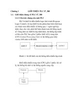
SYSTEM DIAGRAM
Brake Fluid Level Warning Switch
Front Passenger Seat Belt
Warning Light (Clock Assembly)
Light Control
Rheostat
Turn Signal Flasher
Washer Level Warning Switch
(*1 )
Fuel Sender Gauge Assembly
Steering Pad Switch
A/C Control Amplifier
Certification ECU
Engine Oil Pressure Switch
Combination
Meter
Assembly
ECM
Skid Control ECU
Main Body ECU
*1: with Washer Level Warning Light
Cener Airbag Sensor Assembly
Tire Pressure Warning ECU (*2)
*2: with Tire Pressure Warning System
: CAN
: Direct Line
E128116E02
ME–6
METER – METER / GAUGE SYSTEM
ME
INPUT AND OUTPUT SIGNALS OF THE COMBINATION METER ASSEMBLY:
Sender Receiver Communication Signal Communication Line
Combination Meter Assembly
•ECM
• A/C Control Amplifier
• Center Airbag Sensor
Assembly
• Main Body ECU
Vehicle speed signal
CAN (CAN No. 1 Bus)
Certification ECU CAN (CAN MS Bus)
• Main Body ECU
• A/C Control Amplifier
Rheostat duty signal
CAN (CAN No. 1 Bus)
Tail cancel signal
Main Body ECU Lounge illumination signal CAN (CAN No. 1 Bus)
• Center Airbag Sensor
Assembly
•ECM
Vehicle specification signal
(Destination/Handle code)
CAN (CAN No. 1 Bus)
Certification ECU Odometer signal CAN (CAN MS Bus)
Clock assembly
Passenger seat belt warning light
signal
Direct Line
ECM Combination Meter Assembly
Starter signal
CAN (CAN No. 1 Bus)
Test mode signal
Cruise operation indicator
Cruise control warning
Charge light indicator
TM oil temperature range
Engine coolant temperature
signal
Engine type information
Shift position signal (*1)
Reject buzzer signal
Gear position signal
Sports mode indicator (*1)
Engine RPM data
Main Body ECU Combination Meter Assembly
Illuminance data
CAN (CAN No. 1 Bus)
Auto dimmer signal
ACC switch signal
Key switch signal
Each door courtesy switch signal
Slide roof signal (*2)
Smart key signal (*3)
Driver side seat belt switch signal
Parking brake switch signal
High beam indicator light signal
Head (*4)/Tail (*5) indicator light
signal
Front fog indicator light signal
• Main Body ECU
• Certification ECU
Combination Meter Assembly Hood courtesy switch signal CAN (CAN MS Bus)
METER – METER / GAUGE SYSTEM
ME–7
ME
*1: for Automatic Transaxle
*2: with Sliding Roof
*3: with Smart Key System
*4: for U.S.A.
*5: for Canada
*6: with VSC
*7: with Tire Pressure Warning System
*8: with Washer Level Warning Light
Certification ECU Combination Meter Assembly
Meter buzzer request signal
CAN (CAN MS Bus)
Each door open display signal
Key lose warning signal (*3)
Low key battery warning signal
(*3)
Shift position warning signal
Steeling lock abnormal warning
(*3)
Steeling lock unlock warning (*3)
Immobiliser Key Identification
Completion
Skid Control ECU Combination Meter Assembly
Vehicle speed signal
CAN (CAN No. 1 Bus)
Brake Warning light Control Flag
ABS Warning Light signal
Slip Indicator light signal (*6)
VSC Warning light signal (*6)
•ECM
•Skid Control ECU
Combination Meter Assembly Diagnosis signal CAN (CAN No. 1 Bus)
A/C Control Amplifier Combination Meter Assembly
Ambient temperature display
signal
CAN (CAN No. 1 Bus)
Center Airbag Sensor Assembly Combination Meter Assembly
Airbag warning light signal CAN (CAN No. 1 Bus)
Front passenger seat condition
signal
Direct Line
Front passenger seat belt
condition signal
Steering Pad Switch Combination Meter Assembly
Steering pad switch operation
signal
Direct Line
Oil Pressure Switch Combination Meter Assembly
Engine oil pressure warning light
signal
Direct Line
Fuel Sender Gauge Assembly Combination Meter Assembly Fuel level signal Direct Line
Turn Signal flasher Combination Meter Assembly Turn LH/RH indicator light signal Direct Line
Tire Pressure Warning ECU (*7) Combination Meter Assembly Tire pressure warning light signal Direct Line
Washer Level Switch (*8) Combination Meter Assembly
Washer fluid level warning light
signal
Direct Line
Brake Fluid Level Warning Switch Combination Meter Assembly
Brake fluid level warning light
signal
Direct Line
Sender Receiver Communication Signal Communication Line
ME–8
METER – METER / GAUGE SYSTEM
ME
SYSTEM DESCRIPTION
1. METER GAUGE
without Multi-information Display:
Engine Coolant Temperature Receiver Gauge
Fuel Receiver Gauge
Tachometer
A/T Shift Indicator
Speedometer
ODO/TRIP Display
- ODO/TRIP Meter
- Outside Temperature
E128076E01
METER – METER / GAUGE SYSTEM
ME–9
ME
METER GAUGE:
WARNING/INDICATOR:
Item Detail
Speedometer Indicates the vehicle speed receiving a signal from the skid Control ECU. (CAN (CAN No. 1 Bus))
Tachometer Indicates the engine speed based on a signal received from the ECM. (CAN (CAN No. 1 Bus))
Engine Coolant Temperature Receiver
Gauge
Indicates the engine coolant temperature based on a signal received from the ECM. (CAN (CAN
No. 1 Bus))
Fuel Receiver Gauge Indicates the fuel level based on a signal the fuel sender gauge. (Direct Line)
Item Detail
TURN SIGNAL Receives a turn signal from the turn signal flasher. (Direct Line)
BEAM Receives a beam signal from the main body ECU. (CAN (CAN No. 1 Bus))
CHARGE Receives a charge light signal from the alternator L terminal. (Direct Line)
CHECK E/G Receives a check engine light signal from the ECM. (Direct Line)
DOOR
Open door indicator light comes on receiving a door condition signal from the main body ECU.
(CAN (CAN MS Bus))
D-BELT
Receives a driver side seat belt signal from the center airbag sensor assembly. (CAN (CAN No. 1
Bus))
P-BELT
Receives a passenger side seat belt signal from the center airbag sensor assembly via the main
body ECU (CAN) and transmits a passenger side seat belt condition signal to the clock assembly.
(Direct Line)
HEAD (*1) Receives a HEAD indicator light signal from main body ECU. (CAN (CAN No. 1 Bus))
TAIL (*2) Receives a TAIL indicator light signal from the main body ECU. (CAN (CAN No. 1 Bus))
A/T SHIFT
Receives an A/T shift condition and A/T gear position signal from the park/neutral position switch
and the ECM. (CAN (CAN No. 1 Bus))
FUEL Receives a fuel signal from the fuel sender gauge. (Direct Line)
ABS Receives an ABS signal from the skid Control ECU. (CAN (CAN No. 1 Bus))
with Multi-information Display:
Engine Coolant Temperature Receiver Gauge
Fuel Receiver Gauge
Tachometer
A/T Shift Indicator
Speedometer
Multi-information Display
Master Caution Indicator Light
E128139E01
ME–10
METER – METER / GAUGE SYSTEM
ME
*1: for U.S.A.
*2: except for U.S.A.
*3: with VSC
*4: with Tire Pressure Warning System
*5: with Washer Level Indicator
HINT:
• The multi-information display has been located in the
center of the combination meter assembly.
• The display shows a message or animation for each
of the functions described in the table below.
MULTI-INFORMATION DISPLAY:
*1: for U.S.A.
*2: Except for U.S.A.
*3: with VSC
SLIP (*3) Receives a SLIP signal from the skid Control ECU. (CAN (CAN No. 1 Bus))
VSC (*3) Receives a VSC signal from the skid Control ECU. (CAN (CAN No. 1 Bus))
BRAKE
Receives a brake signal from the brake fluid level warning switch (Direct Line) and the skid Control
ECU and main body ECU. (CAN (CAN No. 1 Bus))
CRUISE Receives a cruise signal from the ECM. (CAN (CAN No. 1 Bus))
AIRBAG Receives an airbag signal from the center airbag sensor assembly. (CAN (CAN No. 1 Bus))
Oil pressure Receives an oil pressure signal from the engine oil pressure switch. (Direct Line)
Tire pressure (*4) Receives a tire pressure signal from the tire pressure warning ECU. (Direct Line)
Washer (*5) Receives a washer signal from the washer level warning switch. (Direct Line)
Maintenance required (*1)
An oil change reminder light comes on/blinks to remind the driver to change the engine oil
depending on the vehicle driving distance.
Item Detail
Item Detail
Door warning
When a door (driver/passenger/rear left/rear right/back/hood) of the
vehicle is opened or closed, this item displays a warning message and
animation to inform the driver of the condition of the door.
Maintenance required (*1)
• A maintenance required will display the warning message to
remind the driver to change the engine oil depending on the
vehicle driving distance.
• Displays the mode while in the maintenance request reset mode.
ODO/TRIP display
• This display switches between odometer, trip meter A, and trip
meter B in accordance with the operation of the ODO/TRIP
switch.
• It is possible to reset the trip display to keep pressing the trip reset
knob for 0.8 second or more.
Outside temperature display
Displays the outside temperature in accordance with the ambient
temperature signal from the A/C control amplifier.
Average fuel consumption (after refueling)
• Displays the value that has been calculated by the meter CPU,
which is based on the driven distance and the fuel consumption
volume after the ignition switch is on (IG).
• The average fuel consumption exceeds 99.9 or more, the
indication will be "99.9".
Possible running distance
Displays the value that has been calculated by the meter CPU, which
is based on the the fuel consumption volume, fuel level, and vehicle
speed.
Cruising distance Displays the cruising distance after starting the engine.
Average vehicle speed Displays the average vehicle speed after starting the engine.
Warning message
Illuminates or blinks the master warning light and displays a warning
message for each type of system failure.
DTC (Diagnostic Trouble Code) display (*3) Displays the DTCs pertaining to the VSC function.
METER – METER / GAUGE SYSTEM
ME–11
ME
2. MULTI-INFORMATION DISPLAY
Key is Not Inside The Vehicle. (*1)
Key is Not Inside The Vehicle. (*1)
Key is Inside The Vehicle. (*1)
Display Off
Display Off
Warning Mode
Warning: Occurs
Warning: Repaired
Ignition Switch: off
Ignition Switch: off
Warning Mode
Diagnosis Mode
Warning: Occurs
Malfunction: Occurs
Warning: Repaired
Warning Mode
Warning: Occurs
Warning: Repaired
Malfunction: Repaired
Ignition Switch: on (IG)
Ignition Switch: off or on (ACC)
Cruise Information
Display
*1: with Smart Key System
Outside Temperature
Display
*2: Keep pressing the MODE
switch for about 1 second
(*2)
E128064E01
ME–12
METER – METER / GAUGE SYSTEM
ME
*
*
*
*
Warning Mode
Key System (*1)
WATER TEMP
*1: with Smart Key System
Master Caution Indicator Light
Blinks
Master Caution Indicator Light
Comes On
Master Caution Indicator Light
Goes Off
(*2)
(*2)
(*3)
*3: When the vehicle speed is 5 km/h
(3mph) or more, the waring buzzer sounds.
*2: Warning buzzer sounds
when the indication appears.
E128065E01
METER – METER / GAUGE SYSTEM
ME–13
ME
*
Oil Maintenance
System (*5)
Master Caution
Indicator Light Blinks
Master Caution Indicator
Light Comes On
Master Caution
Indicator Light Goes Off
*5: for U.S.A.
*4: with VSC
(*4)
E132650E01
ME–14
METER – METER / GAUGE SYSTEM
ME
3. DIAGNOSIS SYSTEM
HINT:
• The multi-information display shows "DIAG" when
turn the ignition switch on (IG) (See page BC-141 for
Advics, BC-302 for Bosch).
• Diagnosis information can be displayed on the multi-
information display after connecting a jumper wire
between TC and CG of the DLC3 connector.
Key System (*1)
OIL MAINTENANCE
SYSTEM (*5)
MAINT REQD
MAINT REQD
SOON
*1: with Smart Key System
*5: for U.S.A.
E128066E01
C
OK
OK
E128079
METER – METER / GAUGE SYSTEM
ME–15
ME
HOW TO PROCEED WITH
TROUBLESHOOTING
NEXT
NEXT
(a) Check for DTC output.
HINT:
See page CA-25.
NEXT
HINT:
See page ME-19.
NEXT
NEXT
NEXT
1
VEHICLE BROUGHT TO WORKSHOP
2
CUSTOMER PROBLEM ANALYSIS
3
CHECK CAN COMMUNICATION SYSTEM
CAN DTC OUTPUT (PROCEED TO "CAN
COMMUNICATION SYSTEM")
NO CAN DTC (GO TO STEP 4)
4
PROBLEM SYMPTOM CONFIRMATION
5
PROBLEM SYMPTOMS TABLE
6
CIRCUIT INSPECTION
7
REPAIR OR REPLACE
ME–16
METER – METER / GAUGE SYSTEM
ME
NEXT
8
CONFIRMATION TEST
END
METER – METER / GAUGE SYSTEM
ME–17
ME
CUSTOMIZE PARAMETERS
1. COMBINATION METER ASSEMBLY
NOTICE:
Be sure to record the current value before
customizing.
HINT:
The following items can be customized using intelligent
tester.
METER:
HINT:
This setting is only valid for the buzzer which sounds at
the 5 km/h (3 mph) or more.
2. SEAT BELT BUZZER ON/OFF SETTING (Procedure
"A")
The seat belt buzzer ON/OFF setting, which is a setting
of the buzzer function of the combination meter, can
disable the driver and front passenger side seat belt
buzzers.
NOTICE:
• These buzzers should be on for safe driving.
Perform these procedures only if it is necessary
to set the buzzer off (disabled).
• When either the battery cable or the combination
meter connector is disconnected, these buzzers
are set on (enabled).
• Odometer returns to 0 after starting this
procedure, although it is not displayed.
HINT:
"b-oFF" indicates that the buzzer is OFF. "b-on" indicates
that the buzzer is ON. The seat belt buzzer ON/OFF
setting will be finished (the odometer will display "ODO")
if the ODO/TRIP switch is not operated for 10 seconds or
more. In this case, perform step 11 to check that the
buzzer ON/OFF setting is complete. If it is not complete,
start from step 1 again.
(a) Driver and front passenger side seat belt buzzers
(1) Turn the ignition switch on (IG).
(2) Press the ODO/TRIP switch until the odometer
displays "ODO".
(3) Ignition switch off.
(4) Turn the ignition switch on (IG).
(5) Press the ODO/TRIP switch immediately (within
6 seconds) and hold it down for 10 seconds or
more.
(6) Continue holding down the ODO/TRIP switch
and fasten the driver side seat belt.
Display (Item) Default Contents Setting
KEY REMND VOLUM LARGE
Function to change the volume of the key remind warning
buzzer
LARGE, MEDIUM, SMALL
KEY REMND SOUND NORMAL
Function to change the cycle of the key remind warning
buzzer
FAST, NORMAL, SLOW
SEAT-BELT WARN D/P ON Function to change the setting of the seat belt buzzer. D/P on, D ON, P on, D/P off
ME–18
METER – METER / GAUGE SYSTEM
ME
(7) Check that the odometer displays either "b-on"
or "b-oFF".
(8) Press the ODO/TRIP switch to change the
display to "b-oFF".
(9) Ignition switch off.
(10)Turn the ignition switch on (IG).
(11)Check that no buzzer sounds.
(b) Front passenger side seat belt buzzer
(1) Turn the ignition switch on (IG).
(2) Press the ODO/TRIP switch until the odometer
displays "ODO".
(3) Ignition switch off.
(4) Turn the ignition switch on (IG).
(5) Sit in the front passenger seat. Press the ODO/
TRIP switch immediately (within 6 seconds) and
hold it down for 10 seconds or more.
(6) Sit in the front passenger seat. Continue holding
down the ODO/TRIP switch and fasten the front
passenger side seat belt.
(7) Check that the odometer displays either "b-on"
or "b-oFF".
(8) Press the ODO/TRIP switch to change the
display to "b-oFF".
(9) Ignition switch off.
(10)Turn the ignition switch on (IG).
(11)Check that no buzzer sounds.
METER – METER / GAUGE SYSTEM
ME–19
ME
INITIALIZATION
1. OIL MAINTENANCE INFORMATION MODE RESET
OPERATION
HINT:
• The trip meter reset knob is located on the right side
of the combination meter assembly.
• This reset operation is required only for U.S.A
(a) without multi-information display:
(1) Turn the ignition switch on (IG).
(2) Press the ODO/TRIP switch until the odometer
appears.
(3) Ignition switch off.
(4) Turn the ignition switch on (IG).
(5) Turn the ignition switch on (IG) while pressing
and holding the trip meter reset knob. Hold the
trip meter reset knob until the following
conditions are met and 5 seconds have passed.
• When oil change reminder light turns off, the
reset is complete.
(b) with multi-information display:
(1) Turn the ignition switch on (IG).
(2) Press the ODO/TRIP switch until the odometer
appears.
(3) Ignition switch off.
(4) Turn the ignition switch on (IG).
without Multi-information display:
5 Seconds Previous 4 Seconds Previous 3 Seconds Previous
1 Second Previous 2 Seconds Previous
Trip Meter Reset Knob
Oil Change
Reminder Light
E128140E01
ME–20
METER – METER / GAUGE SYSTEM
ME
(5) Turn the ignition switch on (IG) while pressing
and holding the trip meter reset knob. Hold the
trip meter reset knob until the following
conditions are met and 5 seconds have passed.
• The multi-information display shows "MAINT
REQD RESET MODE".
• The master caution indicator light illuminates.
• When oil change reminder light turns off, the
reset is complete.
(6) When "MAINT REQD RESET MODE
COMPLETE" disappears and the master caution
indicator light turns off, the reset is complete.
with Multi-information display:
5 Seconds Previous 4 Seconds Previous 3 Seconds Previous
1 Second Previous 2 Seconds Previous
Trip Meter Reset Knob
Master Caution
Indicator light
E128141E01
METER – METER / GAUGE SYSTEM
ME–21
ME
PROBLEM SYMPTOMS TABLE
ENTIRE SYSTEM:
METER GAUGES:
WARNING LIGHTS:
Symptom Suspected area See page
Entire combination meter does not operate. Power Source Circuit ME-42
Meter illumination is always dark. Meter Illumination Circuit ME-57
Meter illumination does not dim at night. Meter Illumination Circuit ME-59
Symptom Suspected area See page
Speedometer malfunction Speedometer Circuit ME-44
Tachometer malfunction Tachometer Circuit ME-47
Fuel receiver gauge malfunction Fuel Receiver Gauge Circuit ME-50
Engine coolant temperature malfunction Engine Coolant Temperature Receiver Gauge Circuit ME-54
Symptom Suspected area See page
Check engine warning light does not come on.
1. MIL Circuit (for 2AZ-FE) ES-397
2. MIL Circuit (for 2GR-FE) ES-471
3. Wire Harness or Connector -
4. Combination Meter Assembly ME-63
Charge warning light does not come on.
1. Combination Meter (LED) ME-32
2. Wire Harness or Connector -
3. ECM (for 2AZ-FE) -
4. ECM (for 2GR-FE) -
5. Combination Meter Assembly ME-63
Brake warning light does not come on.
1. Combination Meter (LED) ME-32
2. Wire Harness or Connector -
3. Brake Warning Light Circuit (without VSC) BC-91
4. Brake Warning Light Circuit (with VSC, Bosch Made) BC-404
5 Brake Warning Light Circuit (with VSC, Advics Made) BC-91
6. Main Body ECU -
7. Parking Brake Switch -
8. Combination Meter Assembly ME-63
Brake warning light does not go off.
1. Combination Meter (LED) ME-63
2. Wire Harness or Connector -
3. Brake Warning Light Circuit (without VSC) BC-91
4. Brake Warning Light Circuit (with VSC, Bosch Made) BC-404
5. Brake Warning Light Circuit (with VSC, Advics Made) BC-252
6. Main Body ECU -
7. Parking Brake Switch -
8. Combination Meter Assembly ME-63
ABS warning light does not come on.
1. Combination Meter (LED) ME-32
2. Wire Harness or Connector -
3. ABS Warning Light Circuit (without VSC) BC-78
4. ABS Warning Light Circuit (with VSC, Bosch Made) BC-385
5. ABS Warning Light Circuit (with VSC, Advics Made) BC-233
6. Combination Meter Assembly ME-63
ME–22
METER – METER / GAUGE SYSTEM
ME
ABS warning light does not go off.
1. Combination Meter (LED) ME-32
2. Wire Harness or Connector -
3. ABS Warning Light Circuit (without VSC) BC-78
4. ABS Warning Light Circuit (with VSC, Bosch Made) BC-385
5. ABS Warning Light Circuit (with VSC, Advics) BC-233
6. Combination Meter Assembly ME-63
Airbag warning light does not come on.
1. Combination Meter (LED) ME-32
2. Airbag Warning Light Circuit RS-228
3. Wire Harness or Connector -
4. Combination Meter Assembly ME-63
Airbag warning light does not go off.
1. Combination Meter (LED) ME-32
2. Airbag Warning Light Circuit RS-222
3. Wire Harness or Connector -
4. Combination Meter Assembly ME-63
Open door warning light does not come on.
1. Combination Meter (LED) ME-32
2. Wire Harness or Connector -
3. Door Courtesy Switch LI-129
4. Main Body ECU -
5. Combination Meter Assembly ME-63
Fuel level warning light does not come on.
1. Combination Meter (LED) ME-32
2. Wire Harness or Connector -
3. Fuel Sender Gauge Assembly (for 2AZ-FE) ME-71
4. Fuel Sender Gauge Assembly (for 2GR-FE) ME-74
5. Combination Meter Assembly ME-63
Low oil pressure warning light does not come on.
1. Combination Meter (LED) ME-32
2. Wire Harness or Connector -
3. Low Oil Pressure Switch ME-37
4. Combination Meter Assembly ME-63
Driver seat belt warning light does not come on.
1. Combination Meter (LED) ME-32
2. Wire Harness or Connector -
3. Driver Seat Belt Warning Light Circuit SB-9
4. Main Body ECU -
5. Center Airbag Sensor Assembly -
6. Combination Meter Assembly ME-63
Front passenger seat belt warning light does not come
on.
1. Combination Meter (LED) ME-32
2. Wire Harness or Connector -
3. Front Passenger Seat Belt Warning Light Circuit SB-11
4. Combination Meter Assembly ME-63
5. Center Airbag Sensor Assembly -
6. Clock Assembly OT-4
Tire pressure warning light does not come on. (with
Tire Pressure Warning System)
1. Combination Meter (LED) ME-32
2. Wire Harness or Connector -
3. Tire Pressure Warning System TW-65
4. Combination Meter Assembly ME-63
Washer level warning light does not come on (with
washer level warning light). (with Washer Level
Warning Light)
1. Wire Harness or Connector -
2. Combination Meter Assembly -
3. Washer Level Switch -
Symptom Suspected area See page
METER – METER / GAUGE SYSTEM
ME–23
ME
INDICATOR LIGHTS:
VSC warning light does not come on (without Multi-
information Display, with VSC).
1. Combination Meter (LED) ME-32
2. Wire Harness or Connector -
3. VSC Indicator Light Circuit (with VSC, Bosch Made) BC-392
4. VSC Indicator Light Circuit (with VSC, Advics Made) BC-240
5. Combination Meter Assembly ME-63
Symptom Suspected area See page
Shift indicator light does not come on. (for 2AZ-FE,
Automatic Transaxle)
1. Combination Meter (LED) ME-32
2. Wire Harness or Connector -
3. Transmission Range Sensor Circuit AX-39
4. ECM ES-432
5. Combination Meter Assembly ME-63
Shift indicator light does not come on. (for 2GR-FE,
Automatic Transaxle, )
1. Combination Meter (LED) ME-32
2. Wire Harness or Connector -
3. Park/Neutral Position Switch Circuit AX-158
4. Transmission Control Switch Circuit AX-154
5. ECM ES-518
6. Combination Meter Assembly ME-63
Turn indicator light does not come on.
1. Wire Harness or Connector -
2. Turn Indicator Light Circuit LI-12
3. Combination Meter Assembly ME-63
SLIP indicator light does not come on (with VSC).
1. Combination Meter (LED) ME-32
2. Wire Harness or Connector -
3. SLIP Indicator Light Circuit (with VSC, Bosch Made) BC-412
4. SLIP Indicator Light Circuit (with VSC, Advics Made) BC-259
5. Combination Meter Assembly ME-63
SLIP indicator light does not go off (with VSC).
1. Combination Meter (LED) ME-32
2. Wire Harness or Connector -
3. SLIP Indicator Light Circuit (with VSC, Bosch Made) BC-412
4. SLIP Indicator Light Circuit (with VSC, Advics Made) BC-259
5. Combination Meter Assembly ME-63
CRUISE indicator light does not come on.
1. Combination Meter (LED) ME-32
2. Wire Harness or Connector -
3. Cruise Main Indicator Light Circuit CC-34
4. Combination Meter Assembly ME-63
High beam indicator light does not come on.
1. Wire Harness of Connector -
2. Headlight Dimmer Switch -
3. Main Body ECU -
4. Combination Meter Assembly ME-63
Symptom Suspected area See page
ME–24
METER – METER / GAUGE SYSTEM
ME
TERMINALS OF ECU
1. COMBINATION METER ASSEMBLY
Symbols (Terminal No.) Wiring Color Terminal Description Condition
Specified
Condition
B (F2-1) - Body ground G - Body ground Turn indicator light signal
Turn the ignition switch on (IG),
turn signal RH indicator light OFF
Below 1 V
Turn the ignition switch on (IG),
turn signal RH indicator light ON
10 to 14 V
B (F2-2) - Body ground L - Body ground Turn indicator light signal
Turn the ignition switch on (IG),
turn signal LH indicator light OFF
Below 1 V
Turn the ignition switch on (IG),
turn signal LH indicator light ON
10 to 14 V
CHK (F2-4) - Body ground R - Body ground
Malfunction indicator lamp
signal
Turn the ignition switch on (IG),
CHECK ENGINE warning light
ON
Below 3 V
Turn the ignition switch on (IG),
CHECK ENGINE warning light
OFF
10 to 14 V
B/LE (F2-6) - Body ground LG - Body ground
Brake fluid level warning
light signal
Turn the ignition switch on (IG),
BRAKE warning light OFF
10 to 14 V
Turn the ignition switch on (IG),
BRAKE warning light ON
Below 1 V
+S (F2-12) - Body ground V - Body ground Speed signal (Output) Turn the wheel slowly
Pulse generation
(See waveform 1)
SI (F2-14) - Body ground V - Body ground Speed signal (Input)
Turn the ignition switch on (IG),
turn the wheel slowly
Pulse generation
(See waveform 1)
F1 F2
E123358E01
METER – METER / GAUGE SYSTEM
ME–25
ME
*1: with Washer Level Warning Light
*2: with Tire Pressure Warning System
FR (F2-15) - Body ground GR - Body ground Fuel signal
Turn the ignition switch on (IG),
fuel level is FULL
Below 1 V
Turn the ignition switch on (IG),
fuel level is EMPTY
3 to 7 V
FE (F2-16) - Body ground P - Body ground Ground (Fuel ground) Always Below 1 V
B2 (F1-1) - Body ground R - Body ground Battery Always 10 to 14 V
B (F1-2) - Body ground V - Body ground Battery Always 10 to 14 V
WLVL (F1-5) (*1) - Body ground LG - Body ground
Washer level warning
switch signal
Turn the ignition switch on (IG),
washer level warning light ON
Below 1 V
Turn the ignition switch on (IG),
washer level warning light off
10 to 14 V
TIRE (F1-7) (*2) - Body ground L - Body ground
Tire pressure warning light
signal
Turn the ignition switch on (IG),
tire pressure warning light ON
0.9 to 3.2 V
Turn the ignition switch on (IG),
tire pressure warning light off
3.2 V or higher
S (F1-8) - Body ground O - Body ground
Engine oil pressure
warning light signal
Turn the ignition switch on (IG),
engine oil pressure warning light
OFF
10 to 14 V
Turn the ignition switch on (IG),
engine oil pressure warning light
ON
Below 1 V
P/SB (F1-9) - Body ground P - Body ground
Passenger seat belt
warning light signal
Sit on the front passenger seat,
turn the ignition switch on (IG),
front passenger seat belt warning
light OFF
10 to 14 V
Sit on the front passenger seat,
turn the ignition switch on (IG),
front passenger seat belt warning
light Blinks
10 to 14 V ←→
Below 1 V
ILL- (F1-11) - Body ground BR - Body ground Illumination signal Turn the ignition switch on (IG)
10 to 14 V ←→
Below 1 V
E2 (F1-12) - Body ground W-B - Body ground Ground (Power ground) Always Below 1 V
IG+ (F1-13) - Body ground GR - Body ground Ignition switch signal
Turn the ignition switch off Below 1 V
Turn the ignition switch on (IG) 10 to 14 V
CANH (F1-17) - Body ground B - Body ground
CAN communication
signal
CANL (F1-18) - Body ground W - Body ground
CAN communication
signal
DISP (F1-22) - Body ground V - Body ground Steering pad switch signal
Turn the ignition switch on (IG),
DISP switch off
4 to 6 V
Turn the ignition switch on (IG),
DISP switch ON
Below 1 V
CHG- (F1-23) - Body ground L - Body ground
Charge warning light
signal
Turn the ignition switch on (IG),
CHARGE warning light OFF
10 to 14 V
Turn the ignition switch on (IG),
CHARGE warning light ON
Below 1 V
ES (F1-24) - Body ground BR - Body ground Ground (Signal ground) Always Below 1 V
Symbols (Terminal No.) Wiring Color Terminal Description Condition
Specified
Condition