Toyota land cruiser 1998 2007 automatic transmission hộp số tự động xe land cuiser đời 1998 2007
Bạn đang xem bản rút gọn của tài liệu. Xem và tải ngay bản đầy đủ của tài liệu tại đây (1.17 MB, 38 trang )
AT07I-05
D13117
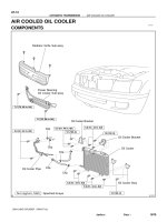
N·m (kgf·cm, ft·lbf) : Specified torque
Clip
Oil Cooler Pipe
Clip
Clip
Clip
Clip
Oil Cooler Stay
Oil Cooler
12 (122, 9)
Oil Cooler Bracket
Radiator Grille Sub-assy
7.5 (76, 66 in.·lbf)
7.5 (76, 66 in.·lbf)
Power Steering
Oil Cooler Sub-assy
Oil Cooler Bracket
5.0 (51, 44 in.·lbf)
5.0 (51, 44 in.·lbf)
5.0 (51, 44 in.·lbf)
5.0 (51, 44 in.·lbf)
5.0 (51, 44 in.·lbf)
12 (122, 9)
12 (122, 9)
AT-16
-AUTOMATIC TRANSMISSION AIR COOLED OIL COOLER
1870Author: Date:
2004 LAND CRUISER (RM1071U)
AIR COOLED OIL COOLER
COMPONENTS
AT07K-05
-AUTOMATIC TRANSMISSION AIR COOLED OIL COOLER
AT-19
1873Author: Date:
INSTALLATION
Installation is in the reverse order of removal (See page AT-17 ).
HINT:
After installtion, check fluid level (See page AT-3-1 ).
AT113-01
D12665
D01688
D01689
D01690
-AUTOMATIC TRANSMISSION AIR COOLED OIL COOLER
AT-17
1871Author: Date:
2004 LAND CRUISER (RM1071U)
REMOVAL
1. REMOVE RADIATOR GRILLE SUB-ASSY
(a) Remove the 3 screws.
(b) Release the 2 clips and remove the radiator grille sub-
assy.
2. SEPARATE POWER STEERING OIL COOLER SUB-
ASSY
Remove the 2 bolts and separate the power steering oil cooler
sub-assy .
Torque: 7.5 N·m (76 kgf·cm, 66 in.·lbf)
3. REMOVE OIL COOLER
(a) Loosen the 2 clips and disconnect the 2 hoses.
(b) Remove the 4 bolts and oil cooler.
Torque: 12 N·m (117 kgf·cm, 8 ft·lbf)
(c) Remove the 8 bolts, the 2 oil cooler brackets and the 2
stays.
Torque: 4.9 N·m (50 kgf·cm, 43 in.·lbf)
D12666
D01692
AT-18
-AUTOMATIC TRANSMISSION AIR COOLED OIL COOLER
1872Author: Date:
2004 LAND CRUISER (RM1071U)
4. REMOVE OIL COOLER PIPE BRACKET
(a) Loosen the 2 clips and disconnect the 2 hoses.
(b) Remove the 2 bolts and the oil cooler pipe bracket.
Torque: 4.9 N·m (50 kgf·cm, 43 in.·lbf)
(c) Loosen the 2 clips and disconnect the 2 hoses.
AT10Z-02
D12704
A
B
Orange
Blue
D12739
D12704
A
B
Orange
Blue
AT-6
-AUTOMATIC TRANSMISSION ATF TEMPERATURE SENSOR
1860Author: Date:
ATF TEMPERATURE SENSOR
ON-VEHICLE REPAIR
1. REMOVE ENGINE NO.2 UNDER COVER
2. DRAIN ATF
3. REMOVE OIL PAN (See page AT-1 1)
4. REMOVE OIL STRAINER (See page AT-1 1)
5. REMOVE ATF TEMPERATURE SENSOR
(a) Disconnect the 7 solenoid valve connectors.
(b) Remove the 2 bolts and disconnect the 2 ATF tempera-
ture sensors.
(c) Disconnect the solenoid connector.
(d) Remove the bolt and the transmission wire harness.
6. INSTALL ATF TEMPERATURE SENSOR
(a) Install the transmission wire harness.
(b) Install the bolt.
Torque: 5.4 N·m (55 kgf·cm, 48 in.·lbf)
(c) Connect the solenoid connector.
(d) Connect the 7 solenoid valve connectors.
(e) Connect the 2 ATF temperature sensors with the 2 bolts.
Torque:
A: 11 N·m (112 kgf·cm, 8 ft·lbf)
B: 10 N·m (100 kgf·cm, 7 ft·lbf)
Bolt length:
Bolt A: 36 mm (1.42 in.)
Bolt B: 12 mm (0.47 in.)
Sensor wire harness:
Wire harness Color
for linear control Orange
for oil temp warning lamp Blue
7. INSTALL OIL STRAINER (See page AT-8 )
8. INSTALL OIL PAN (See page AT-8 )
9. FILL ATF AND CHECK ATF LEVEL (See page AT-3-1 )
10. INSTALL ENGINE NO.2 UNDER COVER
AT07M-02
D12728
Clutch No.2 (C
2
)
Clutch No.3 (C
3
)
Clutch No.1 (C
1
)
One-way Clutch
No.1 (F
1
)
One-way Clutch
No.2 (F
2
)
Brake No.3
(B
3
)
Brake No.1 (B
1
)
Brake No.2 (B
2
)
One-way Clutch
No.3 (F
3
)
Brake No.4 (B
4
)
Shift Solenoid Valve SLT
Shift Solenoid Valve SL1
Shift Solenoid Valve S1
Shift Solenoid Valve S2
Shift Solenoid Valve SR
Shift Solenoid Valve SL2
Shift Solenoid Valve SLU
AT-2
-AUTOMATIC TRANSMISSION AUTOMATIC TRANSMISSION SYSTEM
1853A uthor: Date:
2004 LAND CRUISER (RM1071U)
OPERATION
SL1
Park
Reverse
Neutral
1st
2nd
4th
5th
1st
4th
1st
3rd
1st
1st
S1 C
1
C
2
B
1
B
2
B
3
B
4
F
3
F
1
F
2
: Operating
Gear
Position
Shift Lever
Position
2nd
2nd
2nd
3rd
3rd
R
N
D
4
3
2
L
P
S2 SR
SL2 C
3
SLU
x
x
x
x
x
x
x
x
x
x
x
x
x
x
x
x
x
x
x
x
x
x
x
x
x
x
x
x
x
x
x
x
x
x
x
x
x
x
x
x
x
x
x
x
x
x
x
x
x
x
x
x
x
x
x
x
x
x
x
x
x
x
x
x
x
x
x
x
x
x
x
x
x
x
x
x
x
x
x
x
x
x
x
x
x
x
x
x
x
x
x
x
x
x
x
x
x
x
x
x
x
x
x
x
x
x
x
x
x
x
x
x
x
x
x
x
x
x
x
x
x
x
x
x
x
x
x
x
x
x
x
x
x
x
x
x
x
x
x
x
x
x
x
x
x
x
x
x
x
x
x
x
x
x
x
x
x
x
x
x
x
x
x
x
xx
x
x
x
x
x
x
x
x
x
x
x
x
x
x
x
x
x
x
x
x
x
x
x
x
x
F1, F2, F3 : Operate only when driving
x
-AUTOMATIC TRANSMISSION AUTOMATIC TRANSMISSION SYSTEM
AT-3
1854A uthor: Date:
2004 LAND CRUISER (RM1071U)
AT147-03
D13650
Refill Plug
Overflow Plug
D14352
Overflow Tube
AT-3-1
-AUTOMATIC TRANSMISSION AUTOMATIC TRANSMISSION SYSTEM
1855A uthor: Date:
2004 LAND CRUISER (RM1071U)
AUTOMATIC TRANSMISSION
FLUID
OPERATION
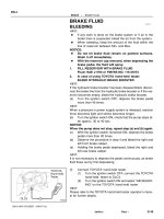
1. BEFORE TRANSMISSION FILL
z This transmission requires Toyota Genuine ATF WS.
z It is necessary to refill the transmission with the correct
amount of fluid.
z The vehicle must remain level while adjusting the trans-
mission fluid level.
z On vehicles equipped with active suspension, turn the
suspension control switch OFF if it is necessary to jack up
the vehicle with the engine running.
2. TRANSMISSION PAN FILL
(a) Remove the refill plug and overflow plug.
(b) Fill the transmission through the refill hole until fluid be-
gins to trickle out of the overflow tube.
(c) Reinstall the overflow plug.
A04550
9 10111213141516
12345678
DLC3
CG
TC
-AUTOMATIC TRANSMISSION AUTOMATIC TRANSMISSION SYSTEM
AT-3-2
1856A uthor: Date:
2004 LAND CRUISER (RM1071U)
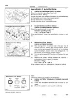
3. TRANSMISSION FILL
(a) Fill the transmission with the correct amount of fluid as
listed in the table below.
(b) Reinstall the refill plug to avoid fluid splash.
Repair Fill Amount
Transmission pan and drain plug remov-
al
1.3 liters (1.37 US qts, 1.14 Imp. qts)
Transmission valve body removal 3.9 liters (4.12 US qts, 3.43 Imp. qts)
Torque converter removal 5.3 liters (5.60 US qts, 4.66 Imp. qts)
Entire transmission assembly 5.3 liters (5.60 US qts, 4.66 Imp. qts)
HINT:
If you cannot add the listed amount of fluid, do the following:
(1) Install the refill plug.
(2) Allow the engine to idle with air conditioning OFF.
(3) Move the shift lever through entire gear range to cir-
culate fluid.
(4) Wait for 30 seconds with the engine idling.
(5) Stop the engine.
(6) Remove the refill plug and add fluid.
(7) Reinstall the refill plug.
4. FLUID CIRCULATION
(a) Allow the engine to idle with the air conditioning OFF.
(b) Move the shift lever through entire gear range to circulate
fluid.
5. FLUID TEMPERATURE CHECK
NOTICE:
The fluid temperature should be less than 30_C (86_F) be-
fore beginning the fluid temperature check.
(a) With hand-held tester
(1) Connect the hand-held tester to the DLC3.
(2) Select the tester menus: OBD/MOBD, ENGINE,
DATA LIST and A/T.
(3) Check A/T OIL TEMP.
(4) Allow the engine to idle until the fluid temperature
reaches 46_C (115_F).
D14352
Overflow Tube
AT-3-3
-AUTOMATIC TRANSMISSION AUTOMATIC TRANSMISSION SYSTEM
1857A uthor: Date:
2004 LAND CRUISER (RM1071U)
(b) Without hand-held tester (Using A/T OIL TEMP indicator)
(1) Connect terminals between CG (4) and TC (13) of
the DLC3 using SST (09843-18040).
(2) Move the shift lever back and forth between N and
D at 1.5 seconds interval for six seconds.
(3) The D shift indicator on the combination meter
comes on for two seconds. This indicates that the
fluid temperature check mode has been started.
(4) The D shift indicator comes on again when the fluid
temperature reaches 46_C (115_F) and blinks
when it exceeds 56_C (130_F).
(5) Allow the engine to idle until the fluid temperature
reaches 46_C (115_F).
6. FLUID LEVEL CHECK
NOTICE:
The fluid temperature must be between 46_C (115_F) and
56_C (130_F) to check the fluid level.
(a) Remove the overflow plug with the engine idling.
(b) Check that the fluid comes out of the overflow tube.
z If fluid does not come out, proceed to step 7.
z If fluid comes out, wait until the overflow slows to a
trickle and proceed to step 8.
7. TRANSMISSION REFILL
(a) Install the overflow plug.
(b) Stop the engine.
(c) Remove the refill plug.
(d) Add 0.4 liters (0.42 US qts, 0.35 lmp. qts) of fluid.
(e) Allow the engine to idle and wait for 10 seconds.
(f) Proceed to step 6.
8. COMPLETE
(a) Install the overflow plug with a new gasket.
(b) Stop the engine.
(c) Install the refill plug with a new gasket.
Torque:
20 N⋅m (205 kgf⋅cm, 15 ft⋅lbf) for overflow plug
39 N⋅m (400 kgf⋅cm, 29 ft⋅lbf) for refill plug
AT07L-02
-AUTOMATIC TRANSMISSION AUTOMATIC TRANSMISSION SYSTEM
AT-1
1852A uthor: Date:
2004 LAND CRUISER (RM1071U)
AUTOMATIC TRANSMISSION SYSTEM
PRECAUTION
If the vehicle is equipped with a mobile communication system, refer to the precautions in the IN section.
AT080-04
D13664
Air Cleaner Cap
Radiator Reservoir
Fan and Fluid
Coupling Assembly
Fan Shroud
x6
x4
80 (820, 59)
80 (820, 59)
80 (820, 59)
80 (820, 59)
Front Propeller Shaft
48 (490, 35)
Hole Plug
18 (185, 13)
Torque Converter
Clutch
50 (510, 37)
74 (750, 54)
50 (510, 37)
N·m (kgf·cm, ft·lbf) : Specified torque
z Non-reusable part
Transfer Case Protector
Engine Mouting
Insulator RR
x4
x6
37 (377, 27)
71 (724, 52)
z
LH Front Exhaust Pipe
z
z
z
Transmission
with Transfer
106 (1,080, 78)
106 (1,080, 78)
106 (1,080, 78)
Ground
Cable
Transmission
Shift Control Rod
Pin
Rear Propeller Shaft
z
z
z
z
RH Front Exhaust Pipe
Transfer Shift
Lever Boot
Upper Console Panel
Transfer Shift Lever Knob
5.4 (55, 48 in.·lbf)
Clip
Transfer Shift
Lever
Engine No. 1
Under Cover
Crossmember
12 (122, 9)
59 (600, 43)
29 (296, 21)
Engine No. 2
Under Cover
z
20 (204, 15)
34 (347, 25)
Oil Cooler Pipe
29 (296, 21)
29 (296, 21)
-AUTOMATIC TRANSMISSION AUTOMATIC TRANSMISSION UNIT
AT-29
1883A uthor: Date:
2004 LAND CRUISER (RM1071U)
AUTOMATIC TRANSMISSION UNIT
COMPONENTS
D01624
AT082-06
-AUTOMATIC TRANSMISSION AUTOMATIC TRANSMISSION UNIT
AT-33
1887Author: Date:
INSTALLATION
1. CHECK TORQUE CONVERTER CLUTCH INSTALLA-
TION
Using calipers and a straight edge, measure the distance from
the installed surface of the transmission housing to the installed
surface of the torque converter clutch.
Correct distance: More than 17.1 mm (0.673 in.)
2. TRANSMISSION INSTALLATION
Installation is in the reverse order of removal
(See page AT-33 ).
HINT:
z Transmission control rod and the park/neutral position
switch (See page DI-361 )
z ATF level (See page AT-3-1 )
z Conduct the road test of the vehicle (See page DI-361 )
AT12V-01
D12652
(a)
(b)
(b)
(c)
Lock
D12653
D12654
D12655
AT-30
-AUTOMATIC TRANSMISSION AUTOMATIC TRANSMISSION UNIT
1884A uthor: Date:
2004 LAND CRUISER (RM1071U)
REMOVAL
1. REMOVE BATTERY
2. REMOVE AIR CLEANER CAP DRIVE BELT, FAN AND
FLUID COUPLING ASSEMBLY, FAN SHROUD AND
RADIATOR RESERVOIR
(See page CO-17 )
3. DISCONNECT CONNECTORS
(a) Release the lock and disconnect the transmission wire
connector.
(b) Disconnect the 2 transmission wire connectors.
(c) Separate the connector clamp.
4. REMOVE TRANSFER SHIFT LEVER BOOT
(a) Remove the transfer shift lever knob.
(b) Remove upper console panel (See page BO-84 ).
(c) Remove the 4 bolts and the transfer shift lever boot.
Torque: 5.4 N·m (55 kgf·cm, 48 in.·lbf)
5. REMOVE ENGINE NO. 1 AND NO. 2 UNDER COVERS
6. REMOVE LH AND RH FRONT EXHAUST PIPES
(See page EM-1 15)
7. REMOVE FRONT AND REAR PROPELLER SHAFTS
(See page PR-4 )
8. SEPARATE TRANSMISSION SHIFT CONTROL ROD
Remove the clip and pin and separate the shift control rod.
9. SEPARATE TRANSFER SHIFT LEVER
Remove the nut and separate the transfer shift lever rod assem-
bly.
Torque: 12 N·m (122 kgf·cm, 9 ft·lbf)
D12656
(a)
(b)
(a)
(a)
(b)
(b)
D12657
D12658
D12659
(c)
(b)
D12660
-AUTOMATIC TRANSMISSION AUTOMATIC TRANSMISSION UNIT
AT-31
1885A uthor: Date:
2004 LAND CRUISER (RM1071U)
10. SEPARATE WIRE HARNESS
(a) Disconnect 3 connectors.
(b) Remove the 3 clamps from the transmission unit and sep-
arate the transmission wire.
11. REMOVE TORQUE CONVERTER CLUTCH MOUNT-
ING BOLT
(a) Remove the bolt and the hole plug.
Torque: 18 N·m (185 kgf·cm, 13 ft·lbf)
(b) Turn the crankshaft to gain access to each bolt.
(c) Hold the crankshaft pulley nut with a wrench, and remove
the 6 bolts.
Torque: 48 N·m (490 kgf·cm, 35 ft·lbf)
HINT:
At the time of installation, first install the green colored bolt. And
then install the other 5 bolts.
12. DISCONNECT OIL COOLER PIPES
(a) Loosen the 2 union nuts.
(b) Remove the bolt and the clamp.
Torque: 12 N·m (122 kgf·cm, 9 ft·lbf)
(c) Remove the 2 union nuts and disconnect the 2 oil cooler
pipes.
Torque: 34 N·m (347 kgf·cm, 25 ft·lbf)
13. SEPARATE GROUND CABLE
Remove the bolt and separate the ground cable.
Torque: 20 N·m (204 kgf·cm, 15 ft·lbf)
14. REMOVE CROSSMEMBER AND TRANSTER CASE
PROTECTOR
(a) Support the transmission with a jack.
Q07409
D12661
Inscribing
Mark
D01622
A
A
B
B
D13665
(a)
(b)
(c)
(d)
(a)
(a)
(a)
(c)
(d)
(e)
(d)
(d)
(e)
(d)
(c)
(c)
(d)
(c)
(e)
(e)
(e)
AT-32
-AUTOMATIC TRANSMISSION AUTOMATIC TRANSMISSION UNIT
1886A uthor: Date:
2004 LAND CRUISER (RM1071U)
(b) Remove the 3 bolts and the transter case protector.
Torque: 29 N·m (296 kgf·cm, 21 ft·lbf)
(c) Remove the 8 bolts, the 2 nuts and the crossmember.
Torque:
Bolt: 50 N·m (510 kgf·cm, 37 ft·lbf)
Nut: 74 N·m (750 kgf·cm, 54 ft·lbf)
15. REMOVE ENGINE MOUNTING INSULATOR RR
Remove the 4 bolts and the engine mounting insulator RR.
Torque: 59 N·m (600 kgf·cm, 43 ft·lbf)
HINT:
At the time of installation, install the insulator rear with the in-
scribing mark facing backward.
16. REMOVE TRANSMISSION
(a) Lower the rear end of the transmission unit.
(b) Remove the transmission wire clamp bolt.
(c) Remove the 10 bolts and the transmission unit.
Torque:
Bolt A: 71 N·m (724 kgf·cm, 52 ft·lbf)
Bolt B: 37 N·m (377 kgf·cm, 27 ft·lbf)
17. REMOVE WIRE HARNESS AND HOSE
(a) Remove the 4 bolts.
Torque: 8.0 N·m (82 kgf·cm, 71 in.·lbf)
(b) Release the lock and disconnect the connector.
(c) Disconnect the 5 connectors.
(d) Separate the 6 connector clamps.
(e) Disconnect the 5 hoses and remove the wire harness and
the hose.
AT07S-04
D12638
N·m (kgf·cm, ft·lbf) : Specified torque
Transmission Control Rod
x6
Shift Lever Assembly
Transfer Shift Lever Knob
Upper Console Panel
8.3 (85, 73 in.·lbf)
13 (130, 9)
AT-20
-AUTOMATIC TRANSMISSION FLOOR SHIFT ASSEMBLY
1874A uthor: Date:
2004 LAND CRUISER (RM1071U)
FLOOR SHIFT ASSEMBLY
COMPONENTS
D12639
Position Indicator Housing
Position Indicator Light Guide
Slide Cover
No. 2 Slide Cover
z Shift Lever Nut
Shift Lever Guide Cushion
Shift Lever Guide
Housing
Bracket
Shift Lock Control ECU
Coller
13 (130, 9)
Plate Washer
z Spacer
z O-Ring
Shift Lever Seal
z O-Ring
z Spacer
Swivel
Plate Washer
Spacer
Shaft Lower
Control Bush
clip
Plate Washer
Control Lever
z
Pin
z Shift Lever Ring
Spring
Detent Shift
Lever Pin
Shift Lever
Sub-assembly
Shift Lock Solenoid
Shift Lever
Nut
Pin
Shift Lever Knob
Transmission
Control Switch ( ↔ D Position)
Shift Lock
Control Switch
Cap
Bulb
Indicator Light Wire
Shift Lock
Release Button
Spring
N·m (kgf·cm, ft·lbf) : Specified torque
z
MP grease
Non-reusable part
Shift Lever
Plate
Transmission
Control Switch
(2 ↔ L Position)
Shift Lock
Solenoid Link
Shift
Lever
Lock Pin
4.9 (50, 43 in.·lbf)
Shift Lock Release Cover
Cushion
Shift Lock
PlateStopper
-AUTOMATIC TRANSMISSION FLOOR SHIFT ASSEMBLY
AT-21
1875A uthor: Date:
2004 LAND CRUISER (RM1071U)
AT114-01
D12642
D12643
-AUTOMATIC TRANSMISSION FLOOR SHIFT ASSEMBLY
AT-23
1877A uthor: Date:
2004 LAND CRUISER (RM1071U)
DISASSEMBLY
1. REMOVE SHIFT LEVER KNOB
2. REMOVE POSITION INDICATOR HOUSING
(a) Using a small screwdriver, remove the shift lock release
cover from the position indicator housing.
(b) Remove the position indicator housing assembly.
3. REMOVE POSITION INDICATOR LIGHT GUIDE
(a) Disconnect the indicator lamp wire from the position indi-
cator light guide.
(b) Remove the position indicator light guide.
4. REMOVE SLIDE COVER AND NO. 2 SLIDE COVER
5. REMOVE SHIFT LEVER GUIDE HOUSING
(a) Disconnect the shift lock control ECU connector from the
shift lever plate.
(b) Disconnect the 2 transmission control switches and the
shift lock control switch from the shift lever guide housing.
(c) Remove the 4 bolts, nuts and the shift lever guide housing
assembly.
6. DISASSEMBLE SHIFT LEVER GUIDE HOUSING
(a) Using a screwdriver, pry up the 3 shift lever nuts.
(b) Using nippers, cut the 3 shift lever nuts off then.
HINT:
Remove the shift lever lock pin of the shift lever nut in the same
way.
(c) Remove the shift lever guide cushion.
(d) Remove the 3 screws, the shift lock control ECU and the
shift lock solenoid.
(e) Remove the shift lock control ECU bracket from the shift
lock control ECU.
(f) Disconnect the transmission control switch connector
from the shift lever guide housing.
(g) Remove the shift lock release button and the spring.
D12644
D04836
D04855
D12645
AT-24
-AUTOMATIC TRANSMISSION FLOOR SHIFT ASSEMBLY
1878A uthor: Date:
2004 LAND CRUISER (RM1071U)
(h) Using a screwdriver, pry up the shift lever nut.
(i) Using nipper, cut the shift lever nut off then.
(j) Remove the shift lever lock pin, the shift lock plate stopper
and the cushion.
7. DISCONNECT SHIFT LOCK CONTROL ECU, SHIFT
LOCK SOLENOID, SHIFT LOCK CONTROL SWITCH
AND TRANSMISSION CONTROL SWITCH
(a) Disengage the secondary locking device of the shift lock
solenoid.
(b) Release the locking lug of the terminal 4 and 5, and pull
the terminals out from the rear.
HINT:
Remove the transmission control switch in the same way.
(c) Remove the shift lock solenoid.
(d) Using 2 mm dia. steel wire, remove the pin and the shift
lock solenoid link from the shift lock solenoid plunger.
(e) Disengage the secondary locking device of the shift lock
control ECU.
(f) Release the locking lag of the terminal 1, 2 and 8 pull the
terminals out from the rear.
(g) Remove the transmission control switch. (D↔ 4)
(h) Release the locking lag of the terminal 5, 6 and 12 and pull
the terminals out from the rear.
(i) Remove the transmission control switch. (2↔L)
(j) Release the locking lag of the terminal 7 and 14 and pull
the terminals out from the rear.
D12646
D12647
D12648
D12649
-AUTOMATIC TRANSMISSION FLOOR SHIFT ASSEMBLY
AT-25
1879A uthor: Date:
2004 LAND CRUISER (RM1071U)
(k) Remove the indicator lamp wire.
8. REMOVE SHIFT LEVER SUB-ASSEMBLY
(a) Using a magnetic finger, remove the detent shift lever pin
and the spring.
(b) Using 2 screwdrivers, remove the shift lever ring.
(c) Remove the pin and shift lever sub-assembly.
9. DISASSEMBLE SHIFT LEVER PLATE
(a) Remove the nut, the control lever, the plate washer, the
2 spacers and the 2 O-rings.
(b) Using pliers, remove the clip.
(c) Remove the swivel, the 2 plate washers, the shaft lower
control bush and the spacer.
(d) Remove the shift lever seal.
(e) Remove the 4 collars.
(f) Remove the 2 spring nuts.
D12641
AT116-01
D12640
AT-28
-AUTOMATIC TRANSMISSION FLOOR SHIFT ASSEMBLY
1882A uthor: Date:
2004 LAND CRUISER (RM1071U)
INSTALLATION
1. INSTALL FLOOR SHIFT LEVER ASSEMBLY
(a) Install the floor shift lever assembly with the 6 bolts.
Torque: 8.3 N·m (85 kgf·cm, 73 in.·lbf)
(b) Connect the connector to the floor shift lever assembly.
2. INSTALL No.1 FLOOR SHIFT GEAR SHIFTING ROD
(a) Shift into the N position.
(b) Connect the No.1 floor shift gear shifting rod and the con-
necting rod swivel with the nut.
Torque: 13 N·m (130 kgf·cm, 9 ft.·lbf)
3. INSTALL UPPER CONSOL PANNEL
(See Page BO-84 )
4. INSTALL TRANSFER SHIFT LEVER KNOB
AT115-01
D12649
D12648
D04855
AT-26
-AUTOMATIC TRANSMISSION FLOOR SHIFT ASSEMBLY
1880A uthor: Date:
2004 LAND CRUISER (RM1071U)
REASSEMBLY
1. REASSEMBLE SHIFT LEVER PLATE
(a) Install the 2 spring nuts.
(b) Install the 4 collars.
(c) Install the shift lever seal.
(d) Install the shaft lower control bush, the spacer, the 2 plate
washers and the swivel.
(e) Using pliers, install the clip.
(f) Apply MP grease to 2 new O-rings.
(g) Install the 2 O-rings, 2 new spacers, the plate washer, the
control lever and the nut.
Torque: 13 N·m (130 kgf·cm, 9 ft·lbf)
2. INSTALL SHIFT LEVER SUB-ASSEMBLY
(a) Apply MP grease to the pin.
(b) Install the shift lever sub-assembly and pin.
(c) Install the shift lever ring.
(d) Apply MP grease to the detent shift lever pin and the
spring.
(e) Install the detent shift lever pin and spring.
3. REASSEMBLE SHIFT LOCK SOLENOID
(a) Apply MP grease to the shift lock solenoid link.
(b) Install the shift lock solenoid link and the pin to the shift
lock solenoid plunger.
(c) Install the shift lock solenoid link with shift lock solenoid
plunger and the spring to the shift lock solenoid.
D12642
-AUTOMATIC TRANSMISSION FLOOR SHIFT ASSEMBLY
AT-27
1881A uthor: Date:
2004 LAND CRUISER (RM1071U)
4. CONNECT SHIFT LOCK CONTROL ECU, SHIFT LOCK
SOLENOID, SHIFT LOCK CONTROL SWITCH, INDI-
CATOR LAMP WIRE AND 2 TRANSMISSION CON-
TROL SWITCH
5. REASSEMBLE SHIFT LEVER GUIDE HOUSING
(a) Apply MP grease to the shift lever lock pin.
(b) Install the shift lever lock pin, the shift lock plate stopper
and the cushion to the shift lever guide housing.
(c) Install a new shift lever nut to the shift lever lock pin by
knocking them lightly via the 10 mm seated nut.
HINT:
Install the shift lever guide cushion of the shift lever nut in the
same way.
(d) Apply MP grease to the shift lock release button.
(e) Install the spring and the shift lock release button.
(f) Connect the transmission control switch connector to the
shift lever guide housing.
(g) Install the shift lock control ECU bracket to the shift lock
control ECU.
(h) Install the shift lock control ECU and the shift lock sole-
noid with the 3 screws to the shift lever guide housing.
(i) Install the shift lever guide cushion with 3 new shift lever
nuts.
6. INSTALL SHIFT LEVER GUIDE HOUSING
(a) Install the shift lever guide housing assembly with the 4
bolts and nuts to the shift lever plate.
Torque: 4.9 N·m (50 kgf·cm, 43 in.·lbf)
(b) Install the 2 transmission control switches and the shift
lock control switch to the shift lever guide housing.
(c) Connect the shift lock control ECU connector to the shift
lever plate.
7. INSTALL SLIDE COVER AND NO. 2 SLIDE COVER
8. INSTALL POSITION INDICATOR LIGHT GUIDE
(a) Install the position indicator light guide.
(b) Connect the indicator lamp wire to the position indicator
light guide.
9. INSTALL POSITION INDICATOR HOUSING
(a) Install the position indicator housing.
(b) Install the shift lock release cover to the position indicator
housing.
10. INSTALL SHIFT LEVER KNOB
AT07T-04
D12640
D12641
AT-22
-AUTOMATIC TRANSMISSION FLOOR SHIFT ASSEMBLY
1876A uthor: Date:
2004 LAND CRUISER (RM1071U)
REMOVAL
1. REMOVE TRANSFER SHIFT LEVER KNOB
2. REMOVE UPPER CONSOLE PANEL
(See page BO-84 )
3. SEPARATE NO. 1 FLOOR SHIFT GEAR SHIFTING
ROD
(a) Shift into the N position.
(b) Remove the nut and separate the No. 1 floor shift gear
shifting rod from the connecting rod swivel.
4. REMOVE FLOOR SHIFT LEVER ASSEMBLY
(a) Disconnect the connector.
(b) Remove the 6 bolts.
Torque: 8.3 N·m (85 kgf·cm, 73 in.·lbf)
(c) Remove the floor shift lever assembly.