Toyota land cruiser 1998 2007 steering hệ thống lái trên xe land cruiser đời 1998 2007
Bạn đang xem bản rút gọn của tài liệu. Xem và tải ngay bản đầy đủ của tài liệu tại đây (1.21 MB, 66 trang )
F04811
Vacuum Hose SR0LZ-06
SR-8
-STEERING AIR CONTROL VALVE
2217Author: Date:
2004 LAND CRUISER (RM1071U)
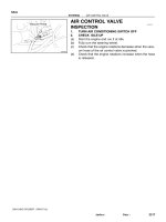
AIR CONTROL VALVE
INSPECTION
1. TURN AIR CONDITIONING SWITCH OFF
2. CHECK IDLE-UP
(a) Start the engine and run it at idle.
(b) Fully turn the steering wheel.
(c) Check that the engine rotations decrease when the vacu-
um hose of the air control valve is pinched.
(d) Check that the engine rotations increase when the hose
is released.
P06717
SR0LW-04
-STEERING DRIVE BELT
SR-3
2212Author: Date:
2004 LAND CRUISER (RM1071U)
DRIVE BELT
INSPECTION
INSPECT DRIVE BELT
Visually check the belt for excessive wear, frayed cords, etc.
If any defect has been found, replace the drive belt.
HINT:
Cracks on the rib side of a belt are considered acceptable. If the
belt has chunks missing from the ribs, it should be replaced.
SR0LX-04
R11229
Normal Abnormal
SR-4
-STEERING POWER STEERING FLUID
2213Author: Date:
2004 LAND CRUISER (RM1071U)
POWER STEERING FLUID
BLEEDING
1. CHECK FLUID LEVEL (See page SR-5 )
2. JACK UP FRONT OF VEHICLE AND SUPPORT IT
WITH STANDS
3. TURN STEERING WHEEL
With the engine stopped, turn the wheel slowly from lock to lock
several times.
4. LOWER VEHICLE
5. START ENGINE
Run the engine at idle for a few minutes.
6. TURN STEERING WHEEL
(a) With the engine idling, turn the wheel to left or right full
lock position and keep it there for 2-3 seconds, then turn
the wheel to the opposite full lock position and keep it
there for 2-3 seconds.
(b) Repeat (a) several times.
7. STOP ENGINE
8. CHECK FOR FOAMING OR EMULSIFICATION
If the system has to be bled twice specifically because of foam-
ing or emulsification, check for fluid leaks in the system.
9. CHECK FLUID LEVEL (See page SR-5 )
SR0LY-05
R00427
R11229
Normal
Abnormal
R11562
Engine Idling
Engine Stopped
5 mm (0.2 in.)
or less
-STEERING POWER STEERING FLUID
SR-5
2214Author: Date:
2004 LAND CRUISER (RM1071U)
INSPECTION
1. CHECK FLUID LEVEL
(a) Keep the vehicle level.
(b) With the engine stopped, check the fluid level in the oil
reservoir.
If necessary, add fluid.
Fluid: ATF DEXRON® II or III
HINT:
Check that the fluid level is within the HOT LEVEL range on the
reservoir.
If the fluid is cold, check that it is within the COLD LEVEL range.
(c) Start the engine and run it at idle.
(d) Turn the steering wheel from lock to lock several times to
boost fluid temperature.
Fluid temperature: 80°C (176°F)
(e) Check for foaming or emulsification.
If there is foaming or emulsification, bleed power steering sys-
tem (See page SR-4 ).
(f) With the engine idling, measure the fluid level in the oil
reservoir.
(g) Stop the engine.
(h) Wait a few minutes and remeasure the fluid level in the oil
reservoir.
Maximum fluid level rise: 5 mm (0.20 in.)
If a problem is found, bleed power steering system
(See page SR-4 ).
(i) Check the fluid level.
F04813
SST
IN OUT
Attachment
Attachment
Pressure Feed Tube
SR-6
-STEERING POWER STEERING FLUID
2215Author: Date:
2004 LAND CRUISER (RM1071U)
2. CHECK STEERING FLUID PRESSURE
(a) Remove the air cleaner assembly with air cleaner hose
(See page SR-40 ).
(b) Disconnect the pressure feed tube from the PS vane
pump (See page SR-40 ).
(c) Connect SST, as shown below.
SST 09640-10010 (09641-01010, 09641-01030,
09641-01060)
NOTICE:
Check that the valve of the SST is in the open position.
(d) Bleed the power steering system (See page SR-4 ).
(e) Start the engine and run it at idle.
(f) Turn the steering wheel from lock to lock several times to
boost fluid temperature.
Fluid temperature: 80 °C (176 °F)
Z15498
PS Gear
Closed
SST
PS Vane
Pump
Oil
Reservoir
Z15499
PS Gear
SST
PS Vane
Pump
Oil
Reservoir
Open
Z15500
PS Gear
SST
PS Vane
Pump
Oil
Reservoir
Open
Lock Position
-STEERING POWER STEERING FLUID
SR-7
2216Author: Date:
2004 LAND CRUISER (RM1071U)
(g) With the engine idling, close the valve of the SST and ob-
serve the reading on the SST.
Minimum fluid pressure:
10,000 kPa (102 kgf/cm
2
, 1,451 psi)
NOTICE:
L Do not keep the valve closed for more than 10 se-
conds.
L Do not let the fluid temperature become too high.
(h) With the engine idling, open the valve fully.
(i) Measure the fluid pressure at engine speeds of 1,000 rpm
and 3,000 rpm.
Difference fluid pressure:
490 kPa (5 kgf/cm
2
, 71 psi) or less
NOTICE:
Do not turn the steering wheel.
(j) With the engine idling and valve fully opened, turn the
steering wheel to full lock.
Minimum fluid pressure:
10,000 kPa (102 kgf/cm
2
, 1,451 psi)
NOTICE:
L Do not maintain lock position for more than 10 se-
conds.
L Do not let the fluid temperature become too high.
(k) Disconnect the SST.
SST 09640- 10010 (09641- 01010, 09641- 01030,
09641-01060)
(l) Connect the pressure feed tube (See page SR-47 ).
(m) Install the air cleaner assembly with air cleaner hose
(See page SR-47 ).
(n) Bleed the power steering system (See page SR-4 ).
SR0MJ-06
F06125
z Cotter Pin
72 (730, 53)
Intermediate Shaft Assembly
34 (350, 25)
120 (1,250, 89)
18 (184, 13)
Tube Clamp
Pressure Feed
Tube
44 (450, 32)
*40 (409, 29)
z Gasket
z
72 (730, 53)
PS Gear Assembly
Return Tube
42 (430, 31)
Clip
Engine Oil Filter Assembly
No. 2 Engine Under Cover
x 6
x 7
No. 1 Engine Under Cover
N·m (kgf·cm, ft·lbf) : Specified torque
z Non-reusable part
* For use with SST
Clip
z O-Ring
18 (180, 13)
Bracket
SR-48
-STEERING POWER STEERING GEAR
2257Author: Date:
2004 LAND CRUISER (RM1071U)
POWER STEERING GEAR
COMPONENTS
F06126
Tie Rod End
Lock Nut
55 (560, 41)
Clip
Rack Boot
z Clamp
z Claw Washer
Rack End
132 (1,350, 98)
*99 (1,014, 74)
Cylinder End
Stopper
z O-Ring
Bushing
Spacer
z Oil Seal
Steering Rack
z O-Ring
z Teflon Ring
Rack Housing
z Claw Washer
z Clamp
Rack Boot
Lock Nut
55 (560, 41)
Clip
Tie Rod End
N·m (kgf·cm, ft·lbf) : Specified torque
z Non-reusable part
Molybdenum disulfide lithium base grease
Power steering fluid
*For use with SST
145 (1,480, 107)
*110 (1,122, 81)
Rack End
132 (1,350, 98)
*99 (1,014, 74)
-STEERING POWER STEERING GEAR
SR-49
2258Author: Date:
2004 LAND CRUISER (RM1071U)
F06127
24.5 (250, 18)
*23 (230, 17)
24.5 (250, 18)
*23 (230, 17)
Turn Pressure Tube
Control Valve
Housing
Dust Cover
18 (180, 13)
z Union Seat
z O-Ring
z Oil Seal
z Bearing
Control Valve
Assembly
z Teflon Ring
z Oil Seal
z O-Ring
Bearing Guide Nut
24.5 (250, 18)
Rack Guide Sub-assembly
Rack Guide Spring
L Rack Guide Spring
Cap
L Rack Guide Spring Cap
Lock Nut
70 (700, 51)
*51 (520, 38)
N·m (kgf·cm, ft·lbf) : Specified torque
z Non-reusable part
L Precoated part
Molybdenum disulfide lithium base grease
Power steering fluid
* For use with SST
SR-50
-STEERING POWER STEERING GEAR
2259Author: Date:
2004 LAND CRUISER (RM1071U)
SR0ML-07
F06129
SST
F06130
SST
F04816
F06131
-STEERING POWER STEERING GEAR
SR-53
2262Author: Date:
2004 LAND CRUISER (RM1071U)
DISASSEMBLY
NOTICE:
When using a vise, do not overtighten it.
1. SECURE PS GEAR ASSEMBLY IN VISE
Using SST, secure the gear assembly in a vise, as shown in the
illustration.
SST 09630-00014 (09631-00142)
2. REMOVE 2 TURN PRESSURE TUBES
Using SST, remove the tube.
SST 09023-38200
3. REMOVE RH AND LH CLIPS, RACK BOOTS AND
CLAMPS
(a) Using pliers, loosen the clamp, as shown in the illustra-
tion.
NOTICE:
Be careful not to damage the boot.
(b) Remove the clip, rack boot and clamp.
(c) Employ the same manner described above to the other
side.
HINT:
Mark the RH and LH rack boots.
4. REMOVE RH AND LH RACK ENDS AND CLAW WASH-
ERS
(a) Using a screwdriver and hammer, stake back the washer.
NOTICE:
Avoid and impact to the steering rack.
F06132
SST
F10798
SST
F10799
Matchmarks
F04822
SST
SR-54
-STEERING POWER STEERING GEAR
2263Author: Date:
2004 LAND CRUISER (RM1071U)
(b) Using a spanner to hold the steering rack steady, and us-
ing SST, remove the rack end.
SST 09922-10010
NOTICE:
Use SST 09922-10010 in the direction shown in the illustra-
tion.
(c) Remove the claw washer.
(d) Employ the same manner described above to the other
side.
HINT:
Mark the RH and LH rack ends.
5. REMOVE RACK GUIDE SPRING CAP LOCK NUT
Using SST, remove the nut.
SST 09922-10010
NOTICE:
Use SST 09922-10010 in the direction shown in the illustra-
tion.
6. REMOVE RACK GUIDE SPRING CAP
7. REMOVE RACK GUIDE SPRING AND RACK GUIDE
SUB-ASSEMBL Y
8. REMOVE DUST COVER
9. REMOVE CONTROL VALVE HOSING WITH CONTROL
VALVE ASSEMBLY
(a) Place matchmarks on the valve housing and rack hous-
ing.
(b) Remove the 2 bolts.
(c) Pull out the control valve assembly with the valve hous-
ing.
(d) Remove the O-ring from the valve housing.
10. REMOVE CONTROL VALVE ASSEMBLY
(a) Using SST, loosen the bearing guide nut.
SST 09631-20060
F04825
Vinyl Tape
F10800
SST
F10801
SST
Press
-STEERING POWER STEERING GEAR
SR-55
2264Author: Date:
2004 LAND CRUISER (RM1071U)
(b) Wind vinyl tape to the control valve shaft.
(c) Using a plastic hammer, tap out the valve assembly with
the nut from the control valve housing.
NOTICE:
Be careful not to damage the oil seal lip.
(d) Remove the nut from the valve assembly.
NOTICE:
Be careful not the damage the oil seal lip.
(e) Remove the O-ring from the nut.
11. REMOVE CYLINDER END STOPPER AND SPACER
(a) Using SST, remove the stopper.
SST 09922-10010
NOTICE:
Use SST 09922-10010 in the direction shown in the illustra-
tion.
(b) Remove the O-ring from the stopper.
12. REMOVE STEERING RACK AND OIL SEAL
(a) Using SST, press out the rack and oil seal.
NOTICE:
Take care not to drop the rack.
SST 09950-70010 (09951-07200)
(b) Remove the oil seal from the rack.
SR1C4-02
R10072
Dial Indicator
F17589
Needle Roller
Bearing
R09561
Bearing
SR-56
-STEERING POWER STEERING GEAR
2265Author: Date:
2004 LAND CRUISER (RM1071U)
INSPECTION
1. INSPECT STEERING RACK
(a) Using a dial indicator, check the rack for runout and for
teeth wear and damage.
Maximum runout: 0.3 mm (0.012 in.)
(b) Check the back surface for wear and damage.
2. INSPECT BEARING
(a) Check the needle roller bearing of the rack housing for pit-
marks or damage.
If faulty, replace the rack housing,
(b) Coat the inside of the bearing with molybdenum disulfide
lithium base grease.
3. INSPECT BEARING
(a) Check the bearing rotation condition and check for abnor-
mal noise.
If the bearing is worn or damaged, replace the control valve as-
sembly.
(b) Coat the bearing with molybdenum disulfide lithium base
grease.
F17185
SR0MO-08
F12855
SST
Fulcrum
Length
F04791
Stopper
-STEERING POWER STEERING GEAR
SR-65
2274Author: Date:
2004 LAND CRUISER (RM1071U)
INSTALLATION
1. INSTALL PS GEAR ASSEMBLY
Torque the 2 new gear assembly set bolts, nuts and washers.
Torque: 120 N·m (1,250 kgf·cm, 89 ft·lbf)
HINT:
Slide the gear assembly to the right side, slide the gear assem-
bly to the left side and position it.
2. INSTALL RH AND LH TIE ROD ENDS AND LOCK NUTS
(a) Screw the lock nut and tie rod end onto the rack end until
the matchmarks are aligned.
(b) After adjusting toe-in, torque the nut (See page
SA-6 ).
Torque: 55 N·m (560 kgf·cm, 41 ft·lbf)
3. CONNECT TUBE CLAMP
Torque the bolt.
Torque: 18 N·m (180 kgf·cm, 13 ft·lbf)
4. CONNECT RETURN TUBE
Using SST, connect the tube.
SST 09023-38400
Torque: 50 N·m (510 kgf·cm, 37 ft·lbf)
HINT:
L Use a torque wrench with a fulcrum length of 300 mm
(11.81 in.).
L This torque value is effective in case that SST is parallel
to a torque wrench.
5. CONNECT PRESSURE FEED TUBE
Torque the union bolt with a new gasket.
HINT:
Make sure the stopper of the pressure feed tube touches the
PS gear assembly as shown in the illustration, then torque the
bolt.
Torque: 42 N·m (430 kgf·cm, 31 ft·lbf)
6. CONNECT NO. 2 INTERMEDIATE SHAFT ASSEMBLY
(See page SR-24 )
7. INSTALL ENGINE OIL FILTER ASSEMBLY
(a) Install a new O-ring.
(b) Torque the 2 bolts and nut with the bracket.
Torque: 18 N·m (180 kgf·cm, 13 ft·lbf)
(c) Connect the 2 clips and hoses.
8. CONNECT RH AND LH TIE ROD ENDS (See page
SA-20 )
9. INSTALL NO. 2 ENGINE UNDER COVER
Tighten the 6 bolts.
SR-66
-STEERING POWER STEERING GEAR
2275Author: Date:
2004 LAND CRUISER (RM1071U)
10. INSTALL NO. 1 ENGINE UNDER COVER
Tighten the 7 bolts.
11. POSITION FRONT WHEELS FACING STRAIGHT
AHEAD
HINT:
Do it with the front of the vehicle jacked up.
12. CENTER SPIRAL CABLE (See page SR-24 )
13. INSTALL STEERING WHEEL
(a) Align the matchmarks on the wheel and steering column
main shaft.
(b) Temporarily tighten the wheel set nut.
(c) Connect the connector.
14. BLEED POWER STEERING SYSTEM (See page
SR-4 )
15. CHECK STEERING WHEEL CENTER POINT
16. TORQUE STEERING WHEEL SET NUT
Torque: 50 N·m (510 kgf·cm, 37 ft·lbf)
17. INSTALL STEERING WHEEL PAD (See page SR-24 )
18. CHECK FRONT WHEEL ALIGNMENT (See page
SA-6 )
19. PERFORM ZERO POINT CALIBRATION OF YAW RATE
AND DECELERATION SENSORS (See page DI-505 )
SR1IN-01
F17593
Rack Teeth End
SST
F10802
SST
F17594
Cylinder End Stopper
Wooden
Block
SR-60
-STEERING POWER STEERING GEAR
2269Author: Date:
2004 LAND CRUISER (RM1071U)
REASSEMBLY
NOTICE:
When using a vise, do not overtighten it.
1. COAT PARTS INDICATED BY ARROWS WITH POWER
STEERING FLUID OR MOLYBDENUM DISULFIDE
LITHIUM BASE GREASE
(See page SR-48 )
2. INSTALL STEERING RACK
(a) Install SST to the rack.
SST 09631-00350
HINT:
If necessary, scrape the burrs off the rack teeth end and bur-
nish.
(b) Coat SST with power steering fluid.
(c) Install the rack into the rack housing.
(d) Remove the SST.
3. INSTALL OIL SEAL
(a) Install SST to the steering rack opposite end.
SST 09631-00350
(b) Coat SST with power steering fluid.
(c) Coat a new oil seal lip with power steering fluid.
(d) Install the oil seal by pushing it onto the SST without tilt-
ing.
NOTICE:
Make sure to install the oil seal facing the correct direction.
(e) Remove the SST.
4. INSTALL SPACER AND CYLINDER END STOPPER
(a) Install the spacer.
(b) Coat a new O-ring with power steering fluid, and install
it to the stopper.
(c) Using a wooden block and hammer, drive in the stopper
until it is tightly installed.
NOTICE:
Be careful not to damage the O-ring.
F04837
Fulcrum
Length
SST
F10803
SST
F04832
Vinyl Tape
F04824
SST
F04823
-STEERING POWER STEERING GEAR
SR-61
2270Author: Date:
2004 LAND CRUISER (RM1071U)
(d) Using SST, torque the stopper.
SST 09922-10010
Torque: 110 N·m (1,122 kgf·cm, 81 ft·lbf)
NOTICE:
Use SST 09922-10010 in the direction shown in the illustra-
tion.
HINT:
Use a torque wrench with a fulcrum length of 380 mm (14.97
in.).
5. AIR TIGHTNESS TEST
(a) Install SST to the unions of the rack housing.
SST 09631-12071
(b) Apply 53 kPa (400 mmHg, 15.75 in.Hg) of vacuum for
about 30 seconds.
(c) Check that there is no change in the vacuum.
If there is change in the vacuum, check the installation of the oil
seals.
6. INSTALL CONTROL VALVE ASSEMBLY
(a) Coat the teflon rings with power steering fluid.
(b) To prevent oil seal lip damage, wind vinyl tape on the ser-
rated part of the control valve shaft.
(c) Push the valve assembly into the control valve housing.
NOTICE:
Be careful not to damage the teflon rings and oil seal lip.
(d) Coat a new O-ring with power steering fluid, and install
it to the bearing guide nut.
(e) Using SST, torque the nut.
SST 09631-20060
Torque: 24.5 N·m (250 kgf·cm, 18 ft·lbf)
NOTICE:
Be careful not to damage the oil seal lip.
(f) Using a punch, stake the nut.
F17180
19°
F17595
SST
F17182
SST
SR-62
-STEERING POWER STEERING GEAR
2271Author: Date:
2004 LAND CRUISER (RM1071U)
7. INSTALL CONTROL VALVE HOUSING WITH CON-
TROL VALVE ASSEMBLY
(a) Coat a new O-ring with power steering fluid, and install
it to the valve housing.
(b) Align the matchmarks on the valve housing and rack
housing, and install the valve housing with the valve as-
sembly to the rack housing.
(c) Torque the 2 bolts.
Torque: 18 N·m (180 kgf·cm, 13 ft·lbf)
8. INSTALL DUST COVER
9. INSTALL RACK GUIDE SUB- ASSEMBLY, RACK
GUIDE SPRING AND RACK GUIDE SPRING CAP
(a) Apply sealant to 2 or 3 threads of the cap.
Sealant:
Part No. 08833-00080, THREE BOND 1344,
LOCTITE 242 or equivalent
(b) Temporarily install the cap.
10. ADJUST TOTAL PRELOAD
(a) To prevent the steering rack teeth from damaging the oil
seal lip, temporarily install the RH and LH rack ends.
(b) Torque the rack guide spring cap.
Torque: 25 N·m (250 kgf·cm, 18 ft·lbf)
(c) Return the cap 19°.
(d) Using SST, turn the control valve shaft right and left 1 or
2 times.
SST 09616-0001 1
(e) Loosen the cap until the rack guide spring is not function-
ing.
(f) Using SST and a torque wrench, tighten the cap until the
preload is within specification.
SST 09616-0001 1
Preload (turning):
Center Area
1.8 - 2.2 N·m (18.4 - 22.4 kgf·cm, 16.0 - 19.5 in.·lbf)
End Area
1.3 - 1.7 N·m (13.3 - 17.3 kgf·cm, 11.5 - 15.0 in.·lbf)
F04836
SST
Fulcrum
Length
F05047
Rack Groove
F17183
Fulcrum Length
SST
-STEERING POWER STEERING GEAR
SR-63
2272Author: Date:
2004 LAND CRUISER (RM1071U)
11. INSTALL RACK GUIDE SPRING CAP LOCK NUT
(a) Apply sealant to 2 or 3 threads of the nut.
Sealant:
Part No.08833-00080, THREE BOND 1344,
LOCTITE 242 or equivalent
(b) Holding the rack guide spring cap rotating, and using
SST, torque the nut.
SST 09922-10010
Torque: 52 N·m (520 kgf·cm, 38 ft·lbf)
NOTICE:
Use SST 09922-10010 in the direction shown in the illustra-
tion.
HINT:
Use a torque wrench with a fulcrum length of 345 mm (14.97
in.).
(c) Recheck the total preload.
Preload (turning):
Center Area
1.8 - 2.2 N·m (18.4 - 22.4 kgf·cm, 16.0 - 19.5 in.·lbf)
End Area
1.3 - 1.7 N·m (13.3 - 17.3 kgf·cm, 11.5 - 15.0 in.·lbf)
(d) Remove the RH and LH rack ends.
12. INSTALL RH AND LH CLAW WASHERS AND RACK
ENDS
(a) Install a new washer, and temporarily tighten the rack
end.
HINT:
Align the claws of the washer with the steering rack grooves.
(b) Using a spanner to hold the steering rack steady, and us-
ing SST, torque the rack end.
SST 09922-10010
Torque: 99 N·m (1,014 kgf·cm, 74 ft·lbf)
NOTICE:
Use SST 09922-10010 in the direction shown in the illustra-
tion.
HINT:
Use a torque wrench with a fulcrum length of 380 mm (13.58
in.).
F17184
Brass Bar
F17596
F05049
F17597
SST
Fulcrum
Length
SR-64
-STEERING POWER STEERING GEAR
2273Author: Date:
2004 LAND CRUISER (RM1071U)
(c) Using a brass bar and hammer, stake the washer.
NOTICE:
Avoid any impact to the rack.
(d) Employ the same manner described above to the other
side.
13. INSTALL RH AND LH RACK BOOTS, CLAMPS AND
CLIPS
(a) Ensure that the tube hole is not clogged with grease.
HINT:
If the tube hole is clogged, the pressure inside the boot will
change after it is assembled and the steering wheel is turned.
(b) Install the boot.
NOTICE:
Be careful not to damage or twist the boot.
(c) Using pliers tighten a new clamp, as shown in the illustra-
tion.
(d) Employ the same manner described above to the other
side.
14. INSTALL 2 TURN PRESSURE TUBES
Using SST, install the tube.
SST 09023-38200
Torque: 23 N·m (230 kgf·cm, 17 ft·lbf)
HINT:
L Use a torque wrench with a fulcrum length of 300 mm
(11.81 in.).
L This torque value is effective in case that SST is parallel
to a torque wrench.
SR0MK-08
F12852
SST
R13479
Matchmarks
-STEERING POWER STEERING GEAR
SR-51
2260Author: Date:
2004 LAND CRUISER (RM1071U)
REMOVAL
NOTICE:
Remove the steering wheel assembly before the steering
gear removal, because there is possibility of breaking of
the spiral cable.
1. PLACE FRONT WHEELS FACING STRAIGHT AHEAD
2. REMOVE STEERING WHEEL PAD
(See page SR-14 )
3. REMOVE STEERING WHEEL (See page SR-14 )
4. REMOVE NO. 1 ENGINE UNDER COVER
Remove the 7 bolts.
5. REMOVE NO. 2 ENGINE UNDER COVER
Remove the 6 bolts.
6. DISCONNECT RH AND LH TIE ROD ENDS
(See page SA-20 )
7. REMOVE ENGINE OIL FILTER ASSEMBLY
(a) Disconnect the 2 clips and hoses.
(b) Remove the 2 bolts and nut with the bracket.
(c) Remove the O-ring.
8. DISCONNECT NO. 2 INTERMEDIATE SHAFT AS-
SEMBLY (See page SR-14 )
HINT:
Turn the steering wheel fully to the right side.
9. DISCONNECT PRESSURE FEED TUBE
Remove the union bolt, gasket and disconnect the pressure
feed tube.
10. DISCONNECT RETURN TUBE
Using SST, disconnect the tube.
SST 09023-38400
11. REMOVE RH AND LH TIE ROD ENDS AND LOCK
NUTS
(a) Place matchmarks on the tie rod end and rack end.
(b) Loosen the lock nut, and remove the tie rod end and lock
nut.
(c) Employ the same manner described above to the other
side.
F06128
SR-52
-STEERING POWER STEERING GEAR
2261Author: Date:
2004 LAND CRUISER (RM1071U)
12. REMOVE PS GEAR ASSEMBLY
Remove the 2 gear assembly set bolts, nuts and washers.
HINT:
Slide the gear assembly to the right side, pull out the left side
of the gear assembly from the member.
SR1C5-02
F04842
Press
SST
Oil
Seal
Bearing
SST
F04843
Press
Oil Seal
SST
SST
F04844
Press
Bearing
Oil Seal
SST
W01749
Press
SST
Oil Seal
W01750
SST
Oil Seal
SST
Press
-STEERING POWER STEERING GEAR
SR-57
2266Author: Date:
2004 LAND CRUISER (RM1071U)
REPLACEMENT
1. IF NECESSARY, REPLACE OIL SEAL AND BEARING
(a) Using SST, press out the oil seal and bearing from the
control valve housing.
SST 09950-60010 (09951-00260),
09950-70010 (09951-07150)
(b) Coat a new oil seal lip with power steering fluid.
(c) Using SST, press in the oil seal.
SST 09950-60010 (09951-00180, 09951-00330,
09952-06010), 09950-70010 (09951-07150)
NOTICE:
Make sure to install the oil seal facing in the correct direc-
tion.
(d) Coat a new bearing with molybdenum disulfide lithium
base grease.
(e) Using SST, press in the bearing.
SST 09950-60010 (09951-00330),
09950-70010 (09951-07150)
2. IF NECESSARY, REPLACE OIL SEAL
(a) Using SST, press out the oil seal from the bearing guide
nut.
SST 09950-60010 (09951-00320),
09950-70010 (09951-07100)
(b) Coat a new oil seal lip with power steering fluid.
(c) Using SST, press in the oil seal.
SST 09950-60010 (09951-00280, 09951-00360,
09952-06010), 09950-70010 (09951-07100)
NOTICE:
Make sure to install the oil seal facing in the correct direc-
tion.
R11302
R16011
Bushing
R10955
R06172
N00401
SR-58
-STEERING POWER STEERING GEAR
2267Author: Date:
2004 LAND CRUISER (RM1071U)
3. INSPECT BUSHING
(a) Check the inside of the bushing of the cylinder end stop-
per for cracks. If faulty, replace the bushing.
(b) Apply molybdenum disulfide lithium base grease to the in-
side of the bushing.
4. IF NECESSARY, REPLACE BUSHING
(a) Using a screwdriver, remove the bushing from the cylin-
der end stopper.
NOTICE:
Be careful not to damage the cylinder end stopper.
(b) Coat the inside of a new bushing with molybdenum disul-
fide lithium base grease.
(c) Install the bushing.
5. IF NECESSARY, REPLACE TEFLON RING AND O-
RING
(a) Using a screwdriver, remove the teflon ring and O-ring
from the steering rack.
NOTICE:
Be careful not to damage the groove for the ring.
(b) Coat a new O-ring with power steering fluid and install it.
(c) Expand a new teflon ring with your fingers.
NOTICE:
Be careful not to overexpand the ring.
(d) Coat the ring with power steering fluid.
(e) Install the ring to the rack, and settle it down with your fin-
gers.
R09564
Z06085
SST
F04830
Screw
Extractor
F04831
Sliding Handle
-STEERING POWER STEERING GEAR
SR-59
2268Author: Date:
2004 LAND CRUISER (RM1071U)
6. IF NECESSARY, REPLACE TEFLON RINGS
(a) Using a screwdriver, remove the 4 teflon rings from the
control valve assembly.
NOTICE:
Be careful not to damage the grooves for the ring.
(b) Expand 4 new rings with your fingers.
NOTICE:
Be careful not to overexpand the ring.
(c) Coat the rings with power steering fluid.
(d) Install the rings to the control valve assembly, and settle
them down with your fingers.
(e) Carefully slide the tapered end of SST over the rings until
the ring fits to the steering rack.
SST 09631-20081
NOTICE:
Be careful not to damage the rings.
7. IF NECESSARY, REPLACE UNION SEAT
(a) Using a screw extractor, remove the union seat from the
control valve housing.
(b) Using plastic hammer and sliding handle, lightly tap in a
new union seat.
NOTICE:
Before installing the union seat, remove dust sticking to
the control valve housing.