Toyota RAV4 1994 2000 automatic transaxle system a540h hộp số tự động a540h trên xe RAV4 đời 1994 2000
Bạn đang xem bản rút gọn của tài liệu. Xem và tải ngay bản đầy đủ của tài liệu tại đây (650.46 KB, 23 trang )
AX04K−02
−AUTOMATIC TRANSAXLE (A540H) AUTOMATIC TRANSAXLE SYSTEM
AX−1
1996 RAV4 (RM447U)
AUTOMATIC TRANSAXLE SYSTEM
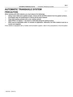
PRECAUTION
When working with FIPG material, you must observe the followings.
S Using a razor blade and a gasket scraper, remove all the old FIPG material from the gasket surfaces.
S Thoroughly clean all components to remove all the loose material.
S Clean both sealing surfaces with a non−residue solvent.
S Apply FIPG in an approx. 1 mm (0.04 in.) wide bead along the sealing surface.
S Parts must be assembled within 10 minutes of application. Otherwise, the FIPG material must be re-
moved and reapplied.
If the vehicle is equipped with a mobile communication system, refer to the precaution in the IN section.
AX04L−01
D00690
Planetary Gear Unit
O/D Direct
Clutch (C
0
)
O/D Brake (B
0
)
1st & Reverse
Brake (B
3
)
One−Way Clutch
No.2 (F
2
)
2nd Brake (B
2
)
Forward
Clutch (C
1
)
2nd Coast
Brake (B
1
)
Direct Clutch (C
2
)
Input Shaft
Front Planetary
Gear
One−Way Clutch
No.1 (F
1
)
Rear Planetary
Gear
Intermediate
Shaft
Counter
Drive Gear
O/D Planetary
Gear
O/D One−Way
Clutch (F
0
)
Shift Lever
Position
Gear Position
C
0
C
1
C
2
B
0
B
1
B
2
B
3
F
0
F
1
F
2
P Parking
Reverse
Neutral
1st
2nd
3rd
O/D
R
N
D
2
L
1st
2nd
*3rd
1st
*2nd
f
f
f
f
f
f
f
f
f
f
f
f
f
f
f
f
f
f
f
f
f
f
f
f
f
f
f
f
f
f
f
f
f
f
f
f
f
f
f
f
f
f
f
f
f
f
f
f
f
*Down−shift only − no up−shift
f : Operating
AX−2
−AUTOMATIC TRANSAXLE (A540H) AUTOMATIC TRANSAXLE SYSTEM
1996 RAV4 (RM447U)
OPERATION
Q06043
SST
AX04M−02
Q06044
SST
−AUTOMATIC TRANSAXLE (A540H) EXTENSION HOUSING OIL SEAL
AX−3
1996 RAV4 (RM447U)
EXTENSION HOUSING OIL SEAL
ON−VEHICLE REPAIR
1. DRAIN TRANSFER OIL
2. REMOVE PROPELLER SHAFT
(See page PR−3)
3. REMOVE EXTENSION HOUSING OIL SEAL
Using SST, remove the oil seal.
SST 09308−00010
4. INSTALL EXTENSION HOUSING OIL SEAL
(a) Using SST and a hammer, driver in a new oil seal.
SST 09325−20010
Oil seal depth: 1.5 ± 0.4 mm (0.059 ± 0.016 in.)
(b) Coat the lip of the oil seal with MP grease.
5. INSTALL PROPELLER SHAFT
(See page PR−9)
6. FILL TRANSFER WITH OIL
(See page DI−173)
Q08739
AX04N−01
Q06120
Vehicle Speed
Sensor
O−Ring
Clip
Driven Gear
Q08737
Q06119
O−Ring
AX−4
−AUTOMATIC TRANSAXLE (A540H) VEHICLE SPEED SENSOR
1996 RAV4 (RM447U)
VEHICLE SPEED SENSOR
ON−VEHICLE REPAIR
1. REMOVE FRONT SPEED SENSOR
(a) Remove the air cleaner assembly.
(b) Disconnect the front speed sensor connector.
(c) Remove the bolt and front speed sensor assembly.
(d) Remove the clip and speedometer driven gear from the
front speed sensor.
(e) Remove the O−ring from the front speed sensor.
2. INSTALL FRONT SPEED SENSOR ASSEMBLY
(a) Coat a new O−ring with ATF and install it to the front
speed sensor.
(b) Install the speedometer driven gear to the front speed
sensor with the clip.
(c) Install the front speed sensor assembly with the bolt.
Torque: 5.4 N·m (55 kgf·cm, 48 in.·lbf)
(d) Connect the front speed sensor connector.
(e) Install the air cleaner assembly.
3. REAR SPEED SENSOR
(a) Remove the air cleaner assembly.
(b) Disconnect the rear speed sensor connector.
(c) Remove the bolt and rear speed sensor.
(d) Remove the O−ring from the rear speed sensor.
4. INSTALL REAR SPEED SENSOR
(a) Coat a new O−ring with ATF and install it to the rear speed
sensor.
(b) Install the rear speed sensor with the bolt.
Torque: 5.4 N·m (55 kgf·cm, 48 in.·lbf)
(c) Connect the rear speed sensor connector.
(d) Install the air cleaner assembly.
Q08865
AX04O−01
−AUTOMATIC TRANSAXLE (A540H) ATF TEMPERATURE SWITCH
AX−5
1996 RAV4 (RM447U)
ATF TEMPERATURE SWITCH
ON−VEHICLE REPAIR
1. REMOVE NO.2 ENGINE UNDER COVER
2. REMOVE ATF TEMPERATURE SWITCH
(a) Disconnect the ATF temperature switch connector.
(b) Remove the ATF temperature switch.
3. INSTALL ATF TEMPERATURE SWITCH
(a) Install the ATF temperature switch.
(b) Connect the ATF temperature switch connector.
4. INSTALL NO.2 ENGINE UNDER COVER
Q08738
AX128−01
Q06066
Q06109
Q06077
N
R
P
AX−6
−AUTOMATIC TRANSAXLE (A540H) PARK/NEUTRAL POSITION (PNP) SWITCH
1996 RAV4 (RM447U)
PARK/NEUTRAL POSITION (PNP)
SWITCH
ON−VEHICLE REPAIR
1. REMOVE NO.2 ENGINE UNDER COVER
2. DISCONNECT PARK/NEUTRAL POSITION SWITCH
CONNECTOR
3. REMOVE PARK/NEUTRAL POSITION SWITCH
(a) Remove the nut and disconnect the shift control cable.
(b) Remove the nut and shift control lever.
(c) Using a screwdriver, pry off the lock plate.
(d) Remove the nut and lock plate.
(e) Remove the 2 bolts and pull out the park/neutral position
switch.
4. INSTALL AND ADJUST PARK/NEUTRAL POSITION
SWITCH
(a) Install the park/neutral position switch to the manual valve
shaft with the 2 bolts and nut.
(b) Install a new lock plate and tighten the nut.
Torque: 6.9 N·m (70 kgf·cm, 61 in.·lbf)
(c) Stake the nut with the lock plate.
(d) Temporarily install the manual valve lever shaft.
(e) Turn the lever counterclockwise until it stops, then turn it
clockwise 2 notches.
(f) Remove the shaft control lever.
Q06078
Neutral
Basic
Line
Groove
Q08738
−AUTOMATIC TRANSAXLE (A540H) PARK/NEUTRAL POSITION (PNP) SWITCH
AX−7
1996 RAV4 (RM447U)
(g) Adjust the park/neutral position switch
(See page AX−6).
HINT:
Align the groove and park/neutral basic line
(h) Tighten the 2 bolts.
Torque: 5.4 N·m (55 kgf·cm, 48 in.·lbf)
(i) Install the shaft control lever with the nut.
Torque: 12.7 N·m (130 kgf·cm, 9 ft·lbf)
(j) Connect the control cable with the nut.
5. CONNECT PARK/NEUTRAL POSITION SWITCH CON-
NECTOR
6. INSTALL NO.2 ENGINE UNDER COVER
Q06064
AX129−01
AT0103
D00691
D00692
AX−8
−AUTOMATIC TRANSAXLE (A540H) VALVE BODY ASSEMBLY
1996 RAV4 (RM447U)
VALVE BODY ASSEMBLY
ON−VEHICLE REPAIR
1. REMOVE NO.2 ENGINE UNDER COVER
2. DRAIN ATF
Using a 10 mm hexagon wrench, remove the drain plug, and
drain the ATF into a suitable container.
3. REMOVE OIL PAN AND GASKET
(a) Remove the 17 bolts.
(b) Remove the oil pan by lifting transaxle case.
NOTICE:
Some fluid remain in the oil pan.
4. EXHAUST PARTICLES IN PAN
Remove the magnet and use it to collect any steel chips.
Lock carefully at the chips and particles in the oil pan and on the
magnet to anticipate when type of wear you will find in the trans-
axle.
S Steel (magnetic): bearing, gear and plate wear
S Brass (non−magnetic): bushing wear
5. REMOVE OIL PIPE BRACKET AND STRAINER
(a) Remove the 2 bolts and oil pipe bracket.
(b) Remove the 3 bolts and strainer.
(c) Remove the gasket from the strainer.
6. REMOVE MANUAL VALVE BODY
(a) Remove the 2 bolts and detent spring.
D00693
Q05896
Q05897
D00645
Q05899
−AUTOMATIC TRANSAXLE (A540H) VALVE BODY ASSEMBLY
AX−9
1996 RAV4 (RM447U)
(b) Remove the 5 bolts and manual valve body with the
manual valve.
(c) Remove the manual valve from the manual valve body.
7. REMOVE OIL PIPE
(a) Remove the bolt and retainer.
(b) Pry up both pipe ends with a large screwdriver and re-
move the 8 pipes.
NOTICE:
Be careful not to bend or damage the pipes.
8. DISCONNECT 3 SOLENOID CONNECTORS
9. REMOVE CONNECTOR CLAMP AND PIPE RETAINER
10. REMOVE B
3
APPLY PIPE
Pry up the pipe with a screwdriver and remove the pipe.
NOTICE:
Be careful not to bend or damage the pipes.
D00694
OR0038
Z13387
A
B
C
D
C
C
D00696
AX−10
−AUTOMATIC TRANSAXLE (A540H) VALVE BODY ASSEMBLY
1996 RAV4 (RM447U)
11. REMOVE VALVE BODY
(a) Remove the 10 bolts.
(b) Disconnect the throttle cable from the cam and remove
the valve body.
12. INSTALL VALVE BODY TO TRANSAXLE CASE
(a) While holding the cam down with your hand, slip the cable
end into the slot.
(b) Raise up the valve body into place.
NOTICE:
Do not entangle the solenoid wire.
(c) Install and tighten the 10 bolts.
Torque: 11 N·m (110 kgf·cm, 8 ft·lbf)
HINT:
S Each bolt length is indicated below.
S Hand−tighten the 10 bolts first, then torque with a torque
wrench.
Bolt length:
Bolt A: 22 mm (0.87 in.)
Bolt B: 32 mm (1.26 in.)
Bolt C: 43 mm (1.69 in.)
Bolt D: 55 mm (2.17 in.)
13. INSTALL B
3
APPLY PIPE
NOTICE:
Be careful not to bend or damage the pipe.
Z13388
A
B
Q05897
Q05896
Z13389
A
B
−AUTOMATIC TRANSAXLE (A540H) VALVE BODY ASSEMBLY
AX−11
1996 RAV4 (RM447U)
14. INSTALL CONNECTOR CLAMP AND PIPE RETAINER
Torque: 11 N·m (110 kgf·cm, 8 ft·lbf)
HINT:
Each bolt length is indicated below.
Bolt length:
Bolt A: 39 mm (1.54 in.)
Bolt B: 43 mm (1.69 in.)
15. CONNECT 3 SOLENOID CONNECTORS
16. INSTALL OIL PIPE
(a) Using a plastic hammer, install the 8 pipes into their posi-
tions.
NOTICE:
Be careful not to bend or damage the pipes.
(b) Install and tighten the bolt and retainer.
Torque: 5.4 N·m (55 kgf·cm, 48 in.·lbf)
17. INSTALL MANUAL VALVE BODY AND DETENT
SPRING
(a) Align the manual valve with the pin on the manual shaft
lever.
(b) Lower the manual valve body into place.
(c) Hand−tighten the 5 bolts first. Then, tighten them with a
torque wrench.
Torque: 11 N·m (110 kgf·cm, 8 ft·lbf)
HINT:
Each bolt length is indicated below.
Bolt length:
Bolt A: 22 mm (0.87 in.)
Bolt B: 37 mm (1.46 in.)
Z13390
A
B
Z13391
A
B
A
B
Q06019
Q06064
AX−12
−AUTOMATIC TRANSAXLE (A540H) VALVE BODY ASSEMBLY
1996 RAV4 (RM447U)
(d) Place the detent springs on the manual valve body and
hand−tighten the 2 bolts first.
Then, tighten them with a torque wrench.
Torque: 11 N·m (110 kgf·cm, 8 ft·lbf)
HINT:
Each bolt length is indicated below.
Bolt length:
Bolt A: 14 mm (0.55 in.)
Bolt B: 37 mm (1.46 in.)
(e) Check that the manual valve lever is touching the center
of the detent spring tip roller.
18. INSTALL PIPE BRACKET AND OIL STRAINER
Torque: 11 N·m (110 kgf·cm, 8 ft·lbf)
HINT:
Each bolt length is indicated below.
Bolt length:
Bolt A: 22 mm (0.87 in.)
Bolt B: 53 mm (2.09 in.)
19. INSTALL MAGNETS IN PLACE
NOTICE:
Make sure that the magnets do not interfere with the oil
pipes.
20. INSTALL OIL PAN WITH NEW GASKET
(a) Install a new gasket and oil pan.
(b) Install and tighten 17 bolts.
Torque: 7.9 N·m (80 kgf·cm, 70 in.·lbf)
21. FILL ATF AND CHECK FLUID LEVEL
(a) Using a 10 mm hexagon wrench, install a new gasket and
the drain plug.
Torque: 49 N·m (500 kgf·cm, 36 ft·lbf)
(b) Fill the ATF and check the fluid level (See page DI−173).
22. INSTALL NO.2 ENGINE UNDER COVER
Q06117
AX04R−02
Q06068
Q05731
0.8 − 1.5 mm (0.031 − 0.059 in.)
200 mm
(7.87 in.)
−AUTOMATIC TRANSAXLE (A540H) THROTTLE CABLE
AX−13
1996 RAV4 (RM447U)
THROTTLE CABLE
ON−VEHICLE REPAIR
1. DISCONNECT THROTTLE CABLE FROM LINKAGE
2. REMOVE PARK/NEUTRAL POSITION SWITCH
(See page AX−6)
3. REMOVE VALVE BODY
(See page AX−8)
4. REMOVE THROTTLE CABLE
(a) Remove the bolt and pull the cable out of the transaxle
case.
(b) Remove the O−ring from the throttle cable.
5. INSTALL THROTTLE CABLE INTO TRANSAXLE
CASE
If the throttle cable is new do the following operations (a) − (c).
(a) Bend the cable so there is a radius of about 200 mm (7.87
in.).
(b) Pull the inner cable lightly until a slight resistance is felt,
and hold it.
(c) Stake the stopper 0.8 − 1.5 mm (0.031 − 0.059 in.) from
the end of outer cable.
(d) Install a new O−ring to the throttle cable.
(e) Make sure to push it in all the way.
(f) Install and torque the bolt.
Torque: 5.4 N·m (55 kgf·cm, 48 in.·lbf)
6. INSTALL VALVE BODY
(See page AX−8)
7. CONNECT THROTTLE CABLE TO LINKAGE
8. ADJUST THROTTLE CABLE
(See page DI−173)
9. INSTALL PARK/NEUTRAL POSITION SWITCH
(See page AX−6)
10. TEST DRIVE VEHICLE
Q06041
SST
AX04S−01
Q06072
Q06040
SST
Q06042
SST
AX−14
−AUTOMATIC TRANSAXLE (A540H) SIDE GEAR SHAFT OIL SEAL
1996 RAV4 (RM447U)
SIDE GEAR SHAFT OIL SEAL
ON−VEHICLE REPAIR
1. REMOVE BOTH DRIVE SHAFTS
(See page SA−20)
2. REMOVE LH SIDE GEAR SHAFT OIL SEAL
Using SST, pull out the oil seal.
SST 09308−00010
3. REMOVE RH SIDE GEAR SHAFT OIL SEAL
Using a screwdriver, remove the oil seal.
4. INSTALL LH SIDE GEAR SHAFT OIL SEAL
(a) Using SST and a hammer, driver in a new oil seal.
SST 09608−32010, 09950−70010 (09951−07100)
Oil seal depth: 0 ± 0.5 mm (0 ± 0.020 in.)
(b) Coat the lip of the oil seal with MP grease.
5. INSTALL RH SIDE GEAR SHAFT OIL SEAL
(a) Using SST and a hammer, drive in a new oil seal.
SST 09608−32010, 09950−70010 (09951−07100)
Oil seal depth: 0 ± 0.5 mm (0 ± 0.020 in.)
(b) Coat the lip of the oil seal with MP grease.
6. INSTALL BOTH DRIVE SHAFTS (See page SA−31)
7. CHECK FLUID LEVEL (See page DI−173)
AX04X−03
Q08861
Key Interlock Solenoid
Stop Light Switch
Shift Lock Override Button Cover
Shift Lock Solenoid
Shift Lock Control Switch
Shift Lock Control ECU
HINT:
S The shift indicator housing ordered as
supply parts does not include the cover
of the shift−lock override button.
So, if you replace the shift indicator
housing, install cover from the old
housing into the new housing.
S Install the cover with its cutout facing
toward the rear of the vehicle.
−AUTOMATIC TRANSAXLE (A540H) SHIFT LOCK SYSTEM
AX−15
1996 RAV4 (RM447U)
SHIFT LOCK SYSTEM
LOCATION
AX0ZJ−02
Z19320
STP
SLS
+
P2
IG
ACC
KLS
+
E
P1
P
SLS
−
Wire Harness Side
ABC
AT5027
AT5029
Battery
AX−16
−AUTOMATIC TRANSAXLE (A540H) SHIFT LOCK SYSTEM
1996 RAV4 (RM447U)
INSPECTION
1. INSPECT SHIFT LOCK CONTROL ECU
Using a voltmeter, measure the voltage at each terminal.
HINT:
Do not disconnect the ECU connector.
Connector Terminal Measuring condition Voltage (V)
A
1 − 3 (ACC − E) IG SW ACC 10 − 14
5 − 3 (IG − E) IG SW ON 10 − 14
4 − 3 (STP − E) Depress brake pedal 10 − 14
2 − 3
(KLS
+
− E)
3. IG SW ACC and shift lever at P position 0
4. Shift lever at R, N, D, 2, L position 7.5 − 11
5. (after approx 1 second) 5.5 − 10
B
2 − 1
(SLS
+
− SLS
−
)
1. IG SW ON and shift lever at P position 0
2. Depress brake pedal 8.5 − 14
3. Except P position 0
C
3 − 2
(P1 − P)
1. IG SW ON, shift lever at P position and depress brake
pedal
0
2. Shift except P position under condition above 10 − 14
1 − 2
(P2 − P)
1. IG SW ACC and shift lever at P position 10 − 14
2. Shift except P position under condition above 0
2. INSPECT SHIFT LOCK SOLENOID
(a) Disconnect the solenoid connector.
(b) Using an ohmmeter, measure resistance between the ter-
minals.
Standard resistance: 26 − 33 Ω
If resistance value is not as specified, replace the solenoid.
(c) Apply battery positive voltage between the terminals.
Check that the solenoid can be heard operating.
If the solenoid does not operated, replace the solenoid.
Q09052
21
Q09053
21
Z19339
2 (P)
1 (P2)
3 (P1)
−AUTOMATIC TRANSAXLE (A540H) SHIFT LOCK SYSTEM
AX−17
1996 RAV4 (RM447U)
3. INSPECT KEY INTERLOCK SOLENOID
(a) Disconnect the solenoid connector.
(b) Using an ohmmeter, measure resistance between the ter-
minals.
Standard resistance: 12.5 − 16.5 Ω
If resistance value is not as specified, replace the solenoid.
(c) Apply battery positive voltage between the terminals.
Check that the solenoid can be heard operating.
If the solenoid does not operated, replace the solenoid.
4. INSPECT SHIFT LOCK CONTROL SWITCH
Inspect that there is continuity between each terminal.
Shift position Tester connection Specified value
P position (Release button
is not pushed)
2 − 3
(P − P1)
Continuity
P position (Release button
is pushed)
2 − 3
(P − P1)
2 − 1
(P − P2)
Continuity
R, N, D, 2, L position
2 − 1
(P − P2)
Continuity
If continuity is not as specified, replace the switch.
AX04T−01
Z19462
Center Stiffener
Plate
Plug for Line
Pressure Test
Starter
Transaxle
Plug for Center
Differential
Control Pressure
Test
Rear End Plate
Stiffener Plate
N·m (kgf·cm, ft·lbf)
: Specified torque
z Non−reusable part
L Precoated part
37 (380, 27)
64 (650, 47)
46 (470, 34)
27 (280, 20)
9.3 (95, 82 in.·lbf)
25 (250, 18)
39 (400, 29)
37 (380, 27)
9.3 (95, 82 in.·lbf)
37 (380, 27)
46 (470, 34)
37 (380, 27)
64 (650, 47)
64 (650, 47)
L
AX−18
−AUTOMATIC TRANSAXLE (A540H) AUTOMATIC TRANSAXLE UNIT
1996 RAV4 (RM447U)
AUTOMATIC TRANSAXLE UNIT
COMPONENTS
Q06113
AX04U−02
Q05857
Z19463
Q05858
−AUTOMATIC TRANSAXLE (A540H) AUTOMATIC TRANSAXLE UNIT
AX−19
1996 RAV4 (RM447U)
REMOVAL
1. REMOVE TRANSAXLE WITH ENGINE (See page
EM−68)
2. REMOVE STARTER
Torque: 39 N·m (400 kgf·cm, 29 ft·lbf)
3. REMOVE STIFFENER PLATE
Remove the 3 bolts and stiffener plate.
Torque: 37 N·m (380 kgf·cm, 27 ft·lbf)
4. REMOVE REAR END PLATE
Remove the 4 bolts and rear end plate.
Torque:
Bolt A: 9.3 N·m (95 kgf·cm, 82 in.·lbf)
Bolt B: 25 N·m (250 kgf·cm, 18 ft·lbf)
5. REMOVE TORQUE CONVERTER CLUTCH MOUNT-
ING BOLTS
Turn the crankshaft to gain access and remove the 6 bolts with
holding the crankshaft pulley nut by a wrench.
Torque: 27 N·m (280 kgf·cm, 20 ft·lbf)
HINT:
At the time of installation, please refer to the following item.
Coat the threads of the bolts with sealant.
Sealant: Part No. 08833 − 00070, THREE BONDS 1324
or equivalent
S Tighten the bolts evenly.
S First install dark green colored bolt and then the 5
bolts.
6. DISCONNECT CONNECTORS AND WIRE HARNESS
FROM TRANSAXLE
Q08839
Q06112
Z17589
AX−20
−AUTOMATIC TRANSAXLE (A540H) AUTOMATIC TRANSAXLE UNIT
1996 RAV4 (RM447U)
7. REMOVE CENTER STIFFENER PLATE
Remove the 4 bolts and stiffener plate.
Torque: 37 N·m (380 kgf·cm, 27 ft·lbf)
8. REMOVE TRANSAXLE WITH TRANSFER ASSEMBLY
(a) Remove the 2 bolts.
Torque: 37 N·m (380 kgf·cm, 27 ft·lbf)
(b) Remove the 5 transaxle mounting bolts.
Torque:
14 mm head bolt: 64 N·m (650 kgf·cm, 47 ft·lbf)
12 mm head bolt: 46 N·m (470 kgf·cm, 34 ft·lbf)
(c) Separate the transaxle assembly.
AT3412
AX04V−01
−AUTOMATIC TRANSAXLE (A540H) AUTOMATIC TRANSAXLE UNIT
AX−21
1996 RAV4 (RM447U)
INSTALLATION
1. CHECK TORQUE CONVERTER CLUTCH INSTALLA-
TION
Using calipers and a straight edge, measure the distance from
the installed surface to front surface of the transaxle housing.
Correct distance: More than 13.7 mm (0.539 in.)
2. TRANSAXLE INSTALLATION
Installation is in the reverse order of removal (See page
AX−19).
HINT:
After installation, check and inspect the following items.
S Fluid level (See page DI−173)
S Front wheel alignment (See page SA−4)
S Do the road test
AT0952
SST
AX04W−01
AT0953
SST
AT3306
Hold
Lock
Free
Turn
AT2821
AX−22
−AUTOMATIC TRANSAXLE (A540H) TORQUE CONVERTER CLUTCH AND DRIVE PLATE
1996 RAV4 (RM447U)
TORQUE CONVERTER CLUTCH
AND DRIVE PLATE
INSPECTION
1. INSPECT ONE−WAY CLUTCH
(a) Install SST into the inner race of the one−way clutch.
SST 09350−32014 (09351−32010)
(b) Install SST so that it fits in the notch of the converter clutch
hub and outer race of the one−way clutch.
SST 09350−32014 (09351−32020)
(c) With the torque converter clutch standing on its side, the
clutch locks when turned counterclockwise, and rotates
freely and smoothly clockwise.
If necessary, clean the converter clutch and retest the clutch.
Replace the converter clutch if the clutch still fails the test.
2. MEASURE DRIVE PLATE RUNOUT AND INSPECT
RING GEAR
(a) Set up a dial indicator and measure the drive plate runout.
(b) Check the damage of the ring gear.
Maximum runout: 0.20 mm (0.0079 in.)
If the runout is not within the specification, or ring gear is dam-
aged replace the drive plate.
Torque: 83 N·m (850 kgf·cm, 61 ft·lbf)
AT4184
−AUTOMATIC TRANSAXLE (A540H) TORQUE CONVERTER CLUTCH AND DRIVE PLATE
AX−23
1996 RAV4 (RM447U)
3. MEASURE TORQUE CLUTCH CONVERTER SLEEVE
RUNOUT
(a) Temporarily mount the torque converter clutch to the drive
plate. Set up a dial indicator and measure the torque con-
verter clutch sleeve runout.
Maximum runout: 0.30 mm (0.0118 in.)
If the runout is not within the specification, try to correct by reori-
enting the installation of the converter clutch.
HINT:
Mark the position of the converter clutch to ensure correct
installation.
(b) Remove the torque converter clutch.