Toyota RAV4 1994 2000 brake system hệ thống thắng xe trên xe RAV4 đời 1994 2000
Bạn đang xem bản rút gọn của tài liệu. Xem và tải ngay bản đầy đủ của tài liệu tại đây (962.48 KB, 47 trang )
BR02F−04
−BRAKE BRAKE SYSTEM
BR−1
1996 RAV4 (RM447U)
BRAKE SYSTEM
PRECAUTION
S Care must be taken to replace each part properly as it could affect the performance of the brake
system and result in a driving hazard. Replace the parts with parts having the same part number
or equivalent.
S It is very important to keep parts and the area clean when repairing the brake system.
S If the vehicle is equipped with a mobile communication system, refer to the precaution in the
IN section.
BR02G−04
BR−2
−BRAKE TROUBLESHOOTING
1996 RAV4 (RM447U)
TROUBLESHOOTING
PROBLEM SYMPTOMS TABLE
Use the table below to help you find the cause of the problem. The numbers indicate the priority of the likely
cause of the problem. Check each part in order. If necessary, replace these parts.
Symptom Suspect Area See page
Lower pedal or spongy pedal
1. Brake system (Fluid leaks)
2. Brake system (Air in)
3. Piston seals (Worn or damaged)
4. Rear Brake shoe clearance (Out of adjustment)
5. Master cylinder (Faulty)
6. Booster push rod (Out of adjustment)
DI−282
−
BR−23
BR−33
BR−9
BR−19
Brake drag
1. Brake pedal freeplay (Minimal)
2. Parking brake lever travel (Out of adjustment)
3. Parking brake wire (Sticking)
4. Rear brake shoe clearance (Out of adjustment)
5. Pad or lining (Cracked or distorted)
6. Piston (Stuck)
7. Piston (Frozen)
8. Anchor or return spring (Faulty)
9. Booster push rod (Out of adjustment)
10. Booster system (Vacuum leaks)
11. Master cylinder (Faulty)
BR−6
BR−8
−
BR−33
BR−20
BR−29
BR−23
BR−23
BR−29
BR−29
BR−19
BR−16
BR−9
Brake pull
1. Piston (Stuck)
2. Pad or lining (Oily)
3. Piston (Frozen)
4. Disc (Scored)
5. Pad or lining (Cracked or distorted)
BR−23
BR−20
BR−29
BR−23
BR−29
BR−20
BR−20
BR−29
−BRAKE TROUBLESHOOTING
BR−3
1996 RAV4 (RM447U)
Hard pedal but brake inefficient
1. Brake system (Fluid leaks)
2. Brake system (Air in)
3. Pad or lining (Worn)
4. Pad or lining (Cracked or distorted)
5. Rear brake shoe clearance (Out of adjustment)
6. Pad or lining (Oily)
7. Pad or lining (Glazed)
8. Disc (Scored)
9. Booster push rod (Out of adjustment)
10. Booster system (Vacuum leaks)
DI−282
−
BR−20
BR−29
BR−20
BR−29
BR−33
BR−20
BR−29
BR−20
BR−29
BR−23
BR−19
BR−16
Noise from brake
1. Pad or lining (Cracked or distorted)
2. Installation bolt (Loose)
3. Disc (Scored)
4. Pad support plate (Loose)
5. Sliding pin (Worn)
6. Pad or lining (Dirty)
7. Pad or lining (Glazed)
8. Anchor or return spring (Faulty)
9. Anti−squeal shim (Damage)
10. Hold−down spring (Damage)
BR−20
BR−29
BR−23
BR−23
BR−23
BR−23
BR−20
BR−29
BR−20
BR−29
BR−29
BR−20
BR−29
R10712
BR02H−02
R10713
R10714
R00252
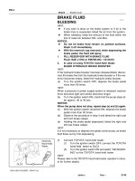
BR−4
−BRAKE BRAKE FLUID
1996 RAV4 (RM447U)
BRAKE FLUID
BLEEDING
HINT:
If any work is done on the brake system or air in the brake lines
is suspected, bleed the system of air.
NOTICE:
Do not let brake fluid remain on a painted surface. Wash it
off immediately.
1. FILL BRAKE RESERVOIR WITH BRAKE FLUID
Fluid: SAEJ1703 or FMVSS No. 116 DOT3
2. BLEED MASTER CYLINDER
HINT:
If the master cylinder has been disassembled or if the reservoir
becomes empty, bleed the master cylinder of the air.
(a) Disconnect the brake lines from the master cylinder.
(b) Slowly depress the brake pedal and hold it.
(c) Block off the outlet plug with your finger and release the
brake pedal.
(d) Repeat (b) and (c) 3 or 4 times.
3. BLEED BRAKE LINE
(a) Connect the vinyl tube to the caliper or wheel cylinder.
(b) Depress the brake pedal several times, then loosen the
bleeder plug with the pedal held down.
(c) At the point when fluid stops coming out, tighten the
bleeder plug, then release the brake pedal.
(d) Repeat (b) and (c) until all the air in the fluid has been bled
out.
(e) Repeat the above procedure to bleed the brake line of the
air for each wheel.
−BRAKE BRAKE FLUID
BR−5
1996 RAV4 (RM447U)
4. CHECK FLUID LEVEL IN RESERVOIR
Check the fluid level and add fluid if necessary.
Fluid: SAEJ1703 or FMVSS No.116 DOT3
R10851
Pedal Height
Push Rod
Stop Light
Switch
BR1DV−01
BR4980
R00935
Pedal Freeplay
BR−6
−BRAKE BRAKE PEDAL
1996 RAV4 (RM447U)
BRAKE PEDAL
ON−VEHICLE INSPECTION
1. CHECK PEDAL HEIGHT
Pedal height from asphalt sheet:
157.1 − 167.1 mm (6.185 − 6.579 in.)
If the pedal height is incorrect, adjust it.
2. IF NECESSARY, ADJUST PEDAL HEIGHT
(a) Disconnect the connector from the stop light switch.
(b) Loosen the stop light switch lock nut and remove the stop
light switch.
(c) Loosen the push rod lock nut.
(d) Adjust the pedal height by turning the pedal push rod.
(e) Tighten the push rod lock nut.
Torque: 25 N·m (260 kgf·cm, 19 ft·lbf)
(f) Install the stop light switch and turn it until it lightly con-
tacts with the pedal stopper.
(g) Turn the stop light switch back one turn.
(h) Check the clearance (A) between stop light switch and
pedal.
Clearance: 0.5 − 2.4 mm (0.020 − 0.094 in.)
(i) Tighten the stop light switch lock nut.
(j) Connect the connector to the stop light switch.
(k) Check that the stop lights come on when the brake pedal
is depressed, and go off when the brake pedal is re-
leased.
(l) After adjusting the pedal height, check the pedal freeplay.
HINT:
If clearance (A) between the stop light switch and the brake
pedal stopper has been adjusted correctly, the pedal freeplay
will meet the specifications.
3. CHECK PEDAL FREEPLAY
(a) Stop the engine and depress the brake pedal several
times until there is no more vacuum left in the booster.
(b) Push in the pedal by hand until the resistance begins to
be felt, then measure the distance, as shown.
Pedal freeplay: 1 − 6 mm (0.04 − 0.24 in.)
R00934
Pedal Reverse
Distance
−BRAKE BRAKE PEDAL
BR−7
1996 RAV4 (RM447U)
HINT:
The freeplay to the 1st point of resistance is due to the play be-
tween the clevis and pin. It is 1 − 3 mm (0.04 − 0.12 in.) on the
pedal.
If incorrect, check the stop light switch clearance. If the clear-
ance is OK, then troubleshoot the brake system.
4. CHECK PEDAL RESERVE DISTANCE
(a) Release the parking brake.
(b) With the engine running, depress the pedal and measure
the pedal reserve distance, as shown.
Pedal reserve distance from asphalt sheet at 490 N
(50 kgf, 110.2 lbf): More than 75 mm (2.95 in.)
If the reserve distance is incorrect, troubleshoot the brake sys-
tem.
R10698
BR02J−10
R10730
Lock Nut
Adjusting
Nut
BR−8
−BRAKE PARKING BRAKE LEVER
1996 RAV4 (RM447U)
PARKING BRAKE LEVER
ON−VEHICLE INSPECTION
1. CHECK PARKING BRAKE LEVER TRAVEL
Pull the parking brake lever all the way up, and count the num-
ber of clicks.
Parking brake lever travel at 196 N (20 kgf, 44 lbf):
5 − 8 clicks
If incorrect, adjust the parking brake.
2. IF NECESSARY, ADJUST PARKING BRAKE
HINT:
Before adjusting the parking brake, make sure that the rear
brake shoe clearance has been adjusted. For shoe clearance
adjustment, see page BR−33.
(a) Remove the rear console box.
(b) Loosen the lock nut and turn the adjusting nut until the le-
ver travel is correct.
(c) Tighten the lock nut.
Torque: 5.4 N·m (55 kgf·cm, 48 in.·lbf)
(d) Install the rear console box.
BR0M2−02
−BRAKE BRAKE MASTER CYLINDER
BR−9
1996 RAV4 (RM447U)
BRAKE MASTER CYLINDER
COMPONENTS
W01346
BR−10
−BRAKE BRAKE MASTER CYLINDER
1996 RAV4 (RM447U)
BR02L−02
W01806
SST
W01807
−BRAKE BRAKE MASTER CYLINDER
BR−11
1996 RAV4 (RM447U)
REMOVAL
1. DISCONNECT LEVEL WARNING SWITCH CONNEC-
TOR
2. DRAW OUT FLUID WITH SYRINGE
NOTICE:
Do not let brake fluid remain on a painted surface. Wash it
off immediately.
3. DISCONNECT R/B NO.2
Remove the 2 bolts and disconnect R/B No.2.
4. REMOVE AIR CLEANER CAP WITH AIR CLEANER
HOSE
5. w/o ABS:
DISCONNECT BRAKE LINES
Using SST, disconnect the 5 brake lines from the master cylin-
der and 3−way.
SST 09023−00100
Torque: 15 N·m (155 kgf·cm, 11 ft·lbf)
6. w/ ABS:
DISCONNECT BRAKE LINES
Using SST, disconnect the 2 brake lines from the master cylin-
der.
SST 09023−00100
Torque: 15 N·m (155 kgf·cm, 11 ft·lbf)
7. M/T:
DISCONNECT CLUTCH RESERVOIR HOSE
8. w/o ABS:
REMOVE MASTER CYLINDER
Remove the 2 nuts and pull out the master cylinder, 3−way and
gasket.
Torque: 13 N·m (130 kgf·cm, 9 ft·lbf)
9. w/ ABS:
REMOVE MASTER CYLINDER
Remove the 2 nuts, and pull out the master cylinder and gasket.
Torque: 13 N·m (130 kgf·cm, 9 ft·lbf)
BR02M−02
R09358
R09359
R12236
A
BR−12
−BRAKE BRAKE MASTER CYLINDER
1996 RAV4 (RM447U)
DISASSEMBLY
1. REMOVE RESERVOIR
(a) Remove the set screw and pull out the reservoir.
Torque:
1.8 N·m (18 kgf·cm, 16 in.·lbf)
(b) Remove the cap and strainer from the reservoir.
2. REMOVE 2 GROMMETS
3. PLACE CYLINDER IN VISE
4. REMOVE PISTON STOPPER BOLT
Using a screwdriver, push the pistons in all the way and remove
the piston stopper bolt and gasket.
HINT:
Tape the screwdriver tip before use.
Torque:
10 N·m (100 kgf·cm, 7 ft·lbf)
5. REMOVE 2 PISTONS AND SPRINGS
(a) Push in the piston with a screwdriver and remove the
snap ring with snap ring pliers.
HINT:
Tape the screwdriver tip before use.
(b) Remove the No.1 piston and spring by hand, pulling
straight out, not at an angle.
NOTICE:
S If pulled out and installed at an angle, there is a possi-
bility that the cylinder bore could be damaged.
S At the time of reassembly, be careful not to damage
the rubber lips on the pistons.
(c) Place a rag and 2 wooden blocks on the work table and
lightly tap the cylinder flange against the block edges until
the piston drops out of the cylinder.
HINT:
Make sure the distance (A) from the rag to the top of the blocks
is at least 100 mm (3.94 in.).
BR02N−03
−BRAKE BRAKE MASTER CYLINDER
BR−13
1996 RAV4 (RM447U)
INSPECTION
HINT:
Clean the disassembled parts with compressed air.
1. INSPECT CYLINDER BORE FOR RUST OR SCORING
2. INSPECT CYLINDER FOR WEAR OR DAMAGE
If necessary, clean or replace the cylinder.
BR02O−03
BR−14
−BRAKE BRAKE MASTER CYLINDER
1996 RAV4 (RM447U)
REASSEMBLY
Reassembly is in the reverse order of disassembly (See page BR−12).
NOTICE:
Apply lithium soap base glycol grease to the rubber parts indicated by the arrows
(See page BR−9).
BR02P−03
−BRAKE BRAKE MASTER CYLINDER
BR−15
1996 RAV4 (RM447U)
INSTALLATION
Installation is in the reverse order of removal (See page BR−11).
1. BEFORE INSTALLATION, ADJUST LENGTH OF BRAKE BOOSTER PUSH ROD
(See page BR−19)
2. AFTER INSTALLATION, FILL BRAKE RESERVOIR WITH BRAKE FLUID, BLEED BRAKE SYS-
TEM (See page BR−4) AND CHECK FOR LEAKS
3. CHECK AND ADJUST BRAKE PEDAL (See page BR−6)
4. M/T:
AFTER INSTALLATION, BLEED CLUTCH SYSTEM
BR2237
BR02Q−02
BR2238
GOOD
1st
2nd
3rd
NO GOOD
BR−16
−BRAKE BRAKE BOOSTER ASSEMBLY
1996 RAV4 (RM447U)
BRAKE BOOSTER ASSEMBLY
ON−VEHICLE INSPECTION
1. OPERATING CHECK
(a) Depress the brake pedal several times with the engine
OFF and check that there is no change in the pedal re-
serve distance.
(b) Depress the brake pedal and start the engine.
If the pedal goes down slightly, operation is normal.
2. AIR TIGHTNESS CHECK
(a) Start the engine and stop it after 1 or 2 minutes. Depress
the brake pedal several times slowly.
If the pedal goes down farthest at the 1st time, but gradually
rises after at the 2nd or 3rd time, the booster is air tight.
(b) Depress the brake pedal while the engine is running, and
stop the engine with the pedal depressed.
If there is no change in the pedal reserve travel after holding the
pedal for 30 seconds, the booster is air−tight.
BR02R−08
−BRAKE BRAKE BOOSTER ASSEMBLY
BR−17
1996 RAV4 (RM447U)
COMPONENTS
BR02S−02
R10718
BR−18
−BRAKE BRAKE BOOSTER ASSEMBLY
1996 RAV4 (RM447U)
REMOVAL
1. REMOVE MASTER CYLINDER (See page BR−9)
2. REMOVE CHARCOAL CANISTER
3. DISCONNECT VACUUM HOSE FROM BRAKE
BOOSTER
4. REMOVE PEDAL RETURN SPRING
5. REMOVE CLIP AND CLEVIS PIN
6. REMOVE BRAKE BOOSTER
(a) Remove the 4 nuts and clevis.
(b) Pull out the brake booster and gasket.
BR0M3−01
F03521
SST
Gasket
N00744
SST
−BRAKE BRAKE BOOSTER ASSEMBLY
BR−19
1996 RAV4 (RM447U)
INSTALLATION
1. INSTALL BRAKE BOOSTER
(a) Install the booster and a new gasket.
(b) Install the clevis to the operating rod.
(c) Install and torque the booster installation nuts.
Torque:
13 N·m (130 kgf·cm, 9 ft·lbf)
(d) Insert the clevis pin into clevis, brake pedal, and install the
clip to the clevis pin.
(e) Install the pedal return spring.
2. ADJUST LENGTH OF BOOSTER PUSH ROD
(a) Install a new gasket on the master cylinder.
(b) Set the SST on the gasket, and lower the pin until its tip
slightly touches the piston.
SST 09737−00010
(c) Turn the SST upside down, and set it on the booster.
SST 09737−00010
(d) Measure the clearance between the booster push rod
and pin head (SST).
Clearance: 0 mm (0 in.)
(e) Adjust the booster push rod length until the push rod
slightly touches the pin head.
3. INSTALL CHARCOAL CANISTER TO ORIGINAL POSI-
TION
4. INSTALL MASTER CYLINDER
5. CONNECT VACUUM HOSE TO BRAKE BOOSTER
6. FILL BRAKE RESERVOIR WITH BRAKE FLUID AND
BLEED BRAKE SYSTEM (See page BR−4)
7. M/T:
BLEED CLUTCH SYSTEM
8. CHECK FOR LEAKS
9. CHECK AND ADJUST BRAKE PEDAL
(See page BR−6)
Check and adjust the brake pedal, then tighten the clevis lock
nut.
Torque:
25 N·m (260 kgf·cm, 19 ft·lbf)
10. DO OPERATIONAL CHECK (See page BR−16)
BR02Y−11
BR−20
−BRAKE FRONT BRAKE PAD
1996 RAV4 (RM447U)
FRONT BRAKE PAD
COMPONENTS
BR0M4−01
R10627
R10628
−BRAKE FRONT BRAKE PAD
BR−21
1996 RAV4 (RM447U)
REPLACEMENT
1. REMOVE FRONT WHEEL
Remove the wheel and temporarily fasten the disc with the hub
nuts.
2. INSPECT PAD LINING THICKNESS
Check the pad thickness through the caliper inspection hole
and replace the pads if they are not within the specification.
Minimum thickness: 1.0 mm (0.039 in.)
3. LIFT UP CALIPER
(a) Remove the flexible hose from the shock absorber brack-
et.
(b) Hold the sliding pin on the bottom and loosen the installa-
tion bolt.
(c) Remove the installation bolt.
(d) Lift up the caliper and suspend it securely.
HINT:
Do not disconnect the flexible hose from the caliper.
4. REMOVE THESE PARTS:
S 2 brake pads
S 4 anti−squeal shims
S 4 pad support plates
NOTICE:
The support plates can be used again provided that they
have sufficient rebound, no deformation, cracks or wear,
and have had all rust, dirt and foreign particles cleaned off.
5. CHECK DISC THICKNESS AND RUNOUT
(See page BR−26)
6. INSTALL 4 PAD SUPPORT PLATES
R10629
BR−22
−BRAKE FRONT BRAKE PAD
1996 RAV4 (RM447U)
7. INSTALL NEW PADS
NOTICE:
When replacing worn pads, the anti−squeal shims must be
replaced together with the pads.
(a) Apply disc brake grease to both side of the inner anti−
squeal shims (See page BR−20).
(b) Install the anti−squeal shim to the inner pad.
(c) Install the inner pad with pad wear indicator plate facing
upward.
(d) Install the outer pad.
NOTICE:
There should be no oil or grease adhering to the friction
surfaces of the pads or the disc.
8. INSTALL CALIPER
(a) Draw out a small amount of brake fluid from the reservoir.
(b) Press in the piston with a hammer handle or an equiva-
lent.
HINT:
If the piston is difficult to push in, loosen the bleeder plug and
push in the piston while letting some brake fluid escape.
(c) Install the caliper.
(d) Hold the sliding pin and torque the installation bolt.
Torque: 26 N·m (270 kgf·cm, 20 ft·lbf)
(e) Install the flexible hose bracket.
Torque: 33 N·m (340 kgf·cm, 25 ft·lbf)
9. INSTALL FRONT WHEEL
10. CHECK THAT FLUID LEVEL IS AT MAX LINE
BR032−14
−BRAKE FRONT BRAKE CALIPER
BR−23
1996 RAV4 (RM447U)
FRONT BRAKE CALIPER
COMPONENTS
BR0M5−01
R10630
BR−24
−BRAKE FRONT BRAKE CALIPER
1996 RAV4 (RM447U)
REMOVAL
1. DISCONNECT FLEXIBLE HOSE
(a) Remove the union bolt and 2 gaskets from the caliper,
then disconnect the flexible hose from the caliper.
Torque: 30 N·m (310 kgf·cm, 22 ft·lbf)
HINT:
At the time of installation, please refer to the following item.
Install the flexible hose lock securely in the lock hole in the cali-
per.
(b) Use a container to catch the brake fluid as it drains out.
2. REMOVE CALIPER
(a) Hold the sliding pin and loosen the 2 installation bolts.
Torque: 26 N·m (270 kgf·cm, 20 ft·lbf)
(b) Remove the 2 installation bolts.
(c) Remove the caliper from the torque plate.
3. REMOVE THESE PARTS:
S 2 brake pads with anti−squeal shims
S 4 pad support plates
BR0M6−01
R10631
R10633
R10634
−BRAKE FRONT BRAKE CALIPER
BR−25
1996 RAV4 (RM447U)
DISASSEMBLY
1. REMOVE CYLINDER BOOT SET RING AND
CYLINDER BOOT
Using a screwdriver, remove the cylinder boot set ring and cylin-
der boot.
2. REMOVE PISTON
(a) Put a piece of cloth or equivalent between the piston and
the caliper.
(b) Use compressed air to remove the piston from the cylin-
der.
CAUTION:
Do not place your fingers in front of the piston when using
compressed air.
3. REMOVE PISTON SEAL
Using a screwdriver, remove the piston seal.
4. REMOVE SLIDING PINS AND DUST BOOTS
(a) Remove the 2 sliding pins from the torque plate.
NOTICE:
At the time of reassembly, please refer to the following
item.
Insert the sliding pin with the sliding bushing into the upper
side.
(b) Using a screwdriver and a hammer, tap out the 2 dust
boots.
HINT:
At the time of reassembly, please refer to the following item.
Use a 21 mm socket and tap in 2 new dust boots into the torque
plate.
NOTICE:
At the time of reassembly, please refer to the following
item.
Confirm that the metal plate portion of the dust boot fits
snugly in the torque plate.