toyota rav4 1994-2000 suspension and axle - hệ thống phuộc nhún và cầu xe trên xe toyota rav4 đời 1994-2000
Bạn đang xem bản rút gọn của tài liệu. Xem và tải ngay bản đầy đủ của tài liệu tại đây (1.8 MB, 100 trang )
SA0T5−01
−SUSPENSION AND AXLE TROUBLESHOOTING
SA−1
1996 RAV4 (RM447U)
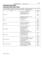
TROUBLESHOOTING
PROBLEM SYMPTOMS TABLE
Use the table below th help you find the cause of the problem. The numbers indicate the priority of the likely
cause of the problem. Check each part in order. If necessary, replace these parts.
Symptom Suspect Area See page
Wander/pulls
1. Tires (Worn or improperly inflated)
2. Wheel alignment (Incorrect)
3. Steering linkage (Loosen or worn)
4. Hub bearings (Loosen or worn)
5. Steering gear (Out of adjustment or broken)
6. Suspension parts (Worn out)
SA−2
SA−4
−
SA−10
SA−52
SA−56
−
−
Bottoming
1. Vehicle (Overloaded)
2. Spring (Weak)
3. Shock absorber (Worn out)
−
SA−32
SA−95
SA−35
SA−92
Sways/pitches
1. Tires (Worn or improperly inflated)
2. Stabilizer bar (Bent or broken)
3. Shock absorber (Worn out)
SA−2
SA−49
SA−35
SA−92
Front wheel shimmy
1. Tires (Worn or improperly inflated)
2. Wheels (Out of balance)
3. Shock absorber (Worn out)
4. Wheel alignment (Incorrect)
5. Ball joints (Worn)
6. Hub bearings (Loosen or worn)
7. Steering linkage (Loosen or worn)
8. Steering gear (Out of adjustment or broken)
SA−2
SA−2
SA−35
SA−2
SA−45
SA−10
−
−
Abnormal tire wear
1. Tires (Improperly inflated)
2. Wheel alignment (Incorrect)
3. Suspension parts (Worn out)
4. Shock absorber (Worn out)
SA−2
SA−4
−
SA−35
SA−92
Noise in rear differential
1. Oil level (Low or wrong grade)
2. Excessive backlash between pinion and ring gear
3. Ring, pinion or side gears (Worn or chipped)
4. Pinion shaft bearing (Worn)
5. Side bearing (Worn)
6. Differential bearing (Loosen or worn)
SA−69
SA−79
SA−79
SA−79
SA−79
SA−79
Oil leak from rear differential
1. Oil level (Too high or wrong grade)
2. Drive pinion oil seal (Worn or damaged)
3. Side gear oil seal (Worn or damaged)
4. Companion flange (Loose or damaged)
5. Side gear shaft (Damaged)
SA−69
SA−79
SA−79
SA−74
SA−79
SA0T6−02
R03031
R14869
R07928
SA−2
−SUSPENSION AND AXLE TIRE AND WHEEL
1996 RAV4 (RM447U)
TIRE AND WHEEL
INSPECTION
1. INSPECT TIRE
(a) Check the tires for wear and proper inflation pressure.
Cold tire inflation pressure
Tire size
Front
kPa (kgf/cm
2
or bar, psi)
Rear
kPa (kgf/cm
2
or bar, psi)
3 Door vehicle
215/70R16 99S
180 (1.8, 26) 180 (1.8, 26)
5 Door vehicle
215/70R16 99S
190 (1.9, 28) 180 (1.8, 26)
(b) Check the tire runout.
Tire runout: 1.0 mm (0.039 in.) or less
2. ROTATING TIRES
HINT:
See the illustration for where to rotate each tire.
3. INSPECT WHEEL BALANCE
(a) Check and adjust the Off−the−car balance.
(b) If necessary, check and adjust the On−the−car−balance.
Imbalance after adjustment: 13.0 g (0.029 lb) or less
R10657
−SUSPENSION AND AXLE TIRE AND WHEEL
SA−3
1996 RAV4 (RM447U)
4. CHECK WHEEL BEARING LOOSENESS
(a) Check the backlash in the bearing shaft direction.
Maximum: 0.05 mm (0.0020 in.)
(b) Check the axle hub deviation.
Maximum: 0.07 mm (0.0028 in.)
5. CHECK FRONT SUSPENSION FOR LOOSENESS
6. CHECK STEERING LINKAGE FOR LOOSENESS
7. CHECK BALL JOINT FOR LOOSENESS
8. CHECK SHOCK ABSORBER WORKS PROPERLY
S Check for oil leak
S Check mounting bushings for wear
S Check bounce for front and rear of the vehicle
R10734
R10735
F02020
Front:
Rear:
SA0T7−05
Z03382
SA3213
A
C
B
Front
D
SA−4
−SUSPENSION AND AXLE FRONT WHEEL ALIGNMENT
1996 RAV4 (RM447U)
FRONT WHEEL ALIGNMENT
INSPECTION
1. MEASURE VEHICLE HEIGHT
Tire size Front*
1
mm (in.) Rear*
2
mm (in.)
215/70R16 (2WD) 227 (8.94) 353 (13.90)
215/70R16 (4WD) 227 (8.94) 360 (14.17)
*
1
: Front measuring point:
Measure from the ground to the center of the lower suspension
arm front mounting bolt.
*
2
: Rear measuring point:
Measure from the ground to the center of the body side No.1
suspension arm mounting bolt.
NOTICE:
Before inspecting the wheel alignment, adjust the vehicle
height to the specification.
If the vehicle height is not to specification, try to adjust it by
pushing down on or lifting the body.
2. INSTALL CAMBER−CASTER−KINGPIN GAUGE
ONTO VEHICLE OR POSITION VEHICLE ON WHEEL
ALIGNMENT TESTER
Follow the specific instructions of the equipment manufacturer.
3. INSPECT CAMBER, CASTER AND STEERING AXIS
INCLINATION
Tire size: 215/70R16
2WD 4WD
Camber
Left−right error
−0°20’ ± 45’
(−0.33°± 0.75°)
45’ (0.75°) or less
−0°15’± 45’
(−0.25° ± 0.75°)
45’ (0.75°) or less
Caster
Left−right error
1°25’ ± 45’
(1.42° ± 0.75°)
45’ (0.75°) or less
1°20 ± 45’
(1.33° ± 0.75°)
45’ (0.75°) or less
Steering axis inclination
Left−right error
11°00’ ± 45’
(11° ± 0.75°)
45’ (0.75°) or less
10°45’ ± 45’
(10.75° ± 0.75°)
45’ (0.75°) or less
If the caster and steering axis inclination are not within the spec-
ification, after the camber has correctly adjusted, recheck the
suspension parts for damaged and/or worn out parts.
4. INSPECT TOE−IN
To e−in
(total)
A + B: 0° ± 0’10’ (0° ± 0.17°)
C − D: 0 ± 2 mm (0 ± 0.08 in.)
If the toe−in is not within the specification, adjust it by the tie rod
end.
R10850
W01204
F01195
Bolt
Set Bolt Adjusting Bolt
1 Dot 2 Dots 3 Dots
30’
45’
1°15’
1°30’
Adjusting
Value
OD=13.9 mm OD=13.3 mm OD=12.4 mm
Original
15’
1°00’
−SUSPENSION AND AXLE FRONT WHEEL ALIGNMENT
SA−5
1996 RAV4 (RM447U)
5. ADJUST CAMBER
NOTICE:
After the camber has been adjusted, inspect the toe−in.
(a) Remove the front wheels.
(b) Remove the 2 nuts on the lower side of the shock absorb-
er.
(c) Coat the threads of the nuts with engine oil.
(d) Temporarily install the 2 nuts.
(e) Adjust the camber by pushing or pulling the lower side of
the shock adjustment is required.
(f) Tighten the 2nuts.
Torque: 158 N·m (1,610 kgf·cm, 117 ft.lbf)
(g) Install the front wheels.
Torque: 103 N·m (1,050 kgf·cm, 76 ft.lbf)
(h) Check the camber.
HINT:
S Try to adjust the camber to the center value.
S Adjusting value for the set bolts is 6’ − 30’ (0.1° − 0.5°).
If the camber is not within the specification, using the table be-
low, estimate for how much additional camber adjustment will
be required, and select the camber adjusting bolt.
W01205
1
2
R10746
R10747
SA0028
AB
Front
AB
A: Inside
B: Outside
SA−6
−SUSPENSION AND AXLE FRONT WHEEL ALIGNMENT
1996 RAV4 (RM447U)
(i) Follow the above mentioned steps again. Between the
step (b) and (c), exchange 1 or 2 selected bolts.
HINT:
When exchanging the 2 bolts, exchange 1 bolt for each time.
6. ADJUST TOE−IN
(a) Remove the boot clamps.
(b) Loosen the tie rod end lock nuts.
(c) Turn the left and right rack ends an equal amount to adjust
the toe−in.
HINT:
S Try to adjust the toe−in to the center value.
S Make sure that the length of the left and right rack ends
is the same.
Tie rod end length difference:
1.5 mm (0.059 in.) or less
(d) Torque the tie rod end lock nuts.
Torque: 56 N·m (570 kgf·cm, 41 ft·lbf)
(e) Place the boot on the seat and install the clamp.
HINT:
Make sure that the boots are not twisted.
7. INSPECT WHEEL ANGLE
Turn the steering wheel fully, and measure the turning angle.
Inside wheel 33°15’ ± 2.0° (33.25° ± 2.0°)
Outside wheel: Reference 28°05’ (28.08°)
If the wheel angles differ from the standard specification, adjust
the toe−in.
SA0T8−05
SA3213
AB
D
Front
C
W01763
−SUSPENSION AND AXLE REAR WHEEL ALIGNMENT
SA−7
1996 RAV4 (RM447U)
REAR WHEEL ALIGNMENT
INSPECTION
1. MEASURE VEHICLE HEIGHT (See page SA−4)
NOTICE:
Before inspect the wheel alignment, adjust the vehicle
height to specification.
2. INSTALL CAMBER−CASTER−KINGPIN GAUGE OR
ONTO WHEEL ALIGNMENT TESTER
Follow the specifications of the equipment manufacturer.
3. INSPECT CAMBER
2WD 4WD
Camber
Left−right error
−1°20’ ± 45’
(−1.33° ± 0.75°)
45’ (0.75°) or less
−1°05’ ± 45’
(−1.08° ± 0.75°)
45’ (0.75°) or less
If the camber is not within the specification, adjust it by the cam-
ber adjust cam.
4. INSPECT TOE−IN
2WD
To e−in
(total)
A + B: 0°20’ ± 0’10’ (0.33° ± 0.17°)
C − D: 4 ± 2 mm (0.16 ± 0.08 in.)
4WD
To e−in
(total)
A + B: 0°15’ ± 0’10’ (0.25° ± 0.17°)
C − D: 3 ± 2 mm (0.12 ± 0.08 in.)
If the toe−in is not within the specification, adjust it by the toe−
adjust cam.
If the toe−in is not within the specification, adjust it by the toe−
adjust cam.
5. ADJUST CAMBER
(a) Loosen the camber adjust cam lock bolt.
(b) Turn the camber adjust cam to adjust camber.
HINT:
S Try to adjust the camber to the center value.
S The camber will change about 16’ (0.27°) with each grad-
uation of the cam.
(c) Torque the lock bolt.
Torque: 113 N·m (1,150 kgf·cm, 83 ft·lbf)
R10782
W01761
SA−8
−SUSPENSION AND AXLE REAR WHEEL ALIGNMENT
1996 RAV4 (RM447U)
6. ADJUST TOE−IN
(a) Measure the distance between each wheel disc and cor-
ner of the cam bracket, then confirm that both are the
same.
Left−right difference: 1 mm (0.04 in.) or less
If the left−right difference is larger than 1 mm (0.04 in.), adjust
it by following the procedures below.
(b) Loosen the toe−adjust cam lock bolt.
(c) Turn the toe−adjust cam an equal amount to adjust toe−
in.
HINT:
S Try it adjust the tie−in to the center value.
S The toe−in will change about 2.5 mm (0.10 in.) with each
graduation of the cam (both side).
(d) Torque the lock bolts.
Torque: 132 N·m (1,350 kgf·cm, 97 ft·lbf)
SA0T9−03
Z19327
49
ABS Speed Sensor
158 (1,610, 117)
49 (500, 36)
8.3 (85, 74 in.·lbf)
127 (1,300, 94)
107 (1,090, 79)
Steering Knuckle
with Axle Hub
Axle Hub
Snap Ring
Oil Seal
Lower Ball Joint
Steering Knuckle
Front Shock Absorber
Lower
Suspension
Arm
Lock Cap
Cotter Pin
z
5 (55, 48 in.·lbf)
Front Drive Shaft
Tie Rod End
Hub Bolt
Disc
Cotter Pin
z
Brake Caliper
Dust Deflectorz
Dust Cover
z
Bearingz
Cotter Pinz
Oil Seal
z
N·m (kgf·cm, ft·lbf)
Non−reusable part
: Specified torque
z
216 (2,200, 159)
127 (1,300, 94)
z
8 (80, 69 in.·lbf)
−SUSPENSION AND AXLE FRONT AXLE HUB
SA−9
1996 RAV4 (RM447U)
FRONT AXLE HUB
COMPONENTS
SA0TA−03
R10657
R10655
SA−10
−SUSPENSION AND AXLE FRONT AXLE HUB
1996 RAV4 (RM447U)
REMOVAL
1. REMOVE FRONT WHEEL
Torque: 103 N·m (1,050kgf·cm, 76 ft·lbf)
2. CHECK BEARING BACKLASH AND AXLE HUB DEVI-
ATION
(a) Remove the 2 bolts and brake caliper from the steering
knuckle.
(b) Support the brake caliper securely.
(c) Remove the disc.
(d) Using a dial indicator near the center of the axle hub and
check the backlash in the bearing shaft direction.
Maximum: 0.05 mm (0.0020 in.)
If the backlash exceeds the maximum, replace the bearing.
(e) Using a dial indicator, check the deviation at the surface
of the axle hub outside the hub bolt.
Maximum: 0.07 mm (0.0028 in.)
If the deviation exceeds the maximum, replace the axle hub and
bearing.
3. REMOVE DRIVE SHAFT LOCK NUT
(a) Install the disc and brake caliper.
Torque: 107 N·m (1,090 kgf·cm, 79 ft·lbf)
(b) Remove the cotter pin and lock cap.
(c) With applying the brakes, remove the nut.
Torque: 216 N·m (2,200 kgf·cm, 159 ft·lbf)
(d) Remove the brake caliper and disc.
4. w/ ABS:
REMOVE ABS SPEED SENSOR AND WIRE HARNESS
FROM STEERING KNUCKLE
Remove the 2 bolts, ABS speed sensor and wire harness.
Torque:
ABS speed sensor x Steering knuckle:
8 N·m (80 kgf·cm, 69 in.·lbf)
ABS speed sensor wire x Steering knuckle:
5 N·m (55 kgf·cm, 48 in.·lbf)
5. LOOSEN 2 NUTS ON LOWER SIDE ON SHOCK AB-
SORBER
Torque: 158 N·m (1,610 kgf·cm, 117 ft·lbf)
HINT:
Do not remove the 2 nuts and bolts.
6. DISCONNECT TIE ROD END FROM STEERING
KNUCKLE
(a) Remove the cotter pin and nut.
Torque: 49 N·m (500 kgf·cm, 36 ft·lbf)
R10678
SST
−SUSPENSION AND AXLE FRONT AXLE HUB
SA−11
1996 RAV4 (RM447U)
(b) Using SST, disconnect the tie rod end from the steering
knuckle.
SST 09610−20012
7. DISCONNECT LOWER BALL JOINT FROM LOWER
ARM
Remove the bolt and 2 nuts.
Torque: 127 N·m (1,300 kgf·cm, 94 ft·lbf)
8. REMOVE STEERING KNUCKLE WITH AXLE HUB
HINT:
At the time of installation, please refer to the following item.
Coat the threads of the nut’s with engine oil.
NOTICE:
Be careful not to damage the oil seal, boot and ABS speed
sensor rotor.
SA0TB−01
R10677
SST
R10676
SST
R10675
SST
SST
F01922
SST
SA−12
−SUSPENSION AND AXLE FRONT AXLE HUB
1996 RAV4 (RM447U)
DISASSEMBLY
1. REMOVE DUST DEFLECTOR
Using a screwdriver, remove the dust deflector.
2. REMOVE LOWER BALL JOINT
(a) Remove the cotter pin and nut.
(b) Using SST, remove the lower ball joint.
SST 09628−62011
3. REMOVE AXLE HUB
(a) Using SST, remove the axle hub.
SST 09520−00031
(b) Using SST, remove the inner race (outside) from the axle
hub.
SST 09950−40010 (09951−04020, 09952−04010,
09953−04020, 09954−04010, 09955−04060,
09957−04010, 09958−04010),
09950−60010 (09951−00370)
4. REMOVE DUST COVER
Remove the 4 bolts and dust cover.
5. REMOVE OIL SEALS
(a) Using SST, remove the inner oil seal.
SST 09308−00010
F01923
SST
R10731
SST
SST
−SUSPENSION AND AXLE FRONT AXLE HUB
SA−13
1996 RAV4 (RM447U)
(b) Using SST, remove the outer oil seal.
SST 09308−00010
6. REMOVE BEARING FROM STEERING KNUCKLE
(a) Using snap ring pliers, remove the snap ring.
(b) Place the inner race on the outside of the bearing.
(c) Using SST and a press, remove the bearing.
SST 09527−17011, 09950−60010 (09951−00540),
09950−70010 (09951−07150)
SA0TC−02
R10732
SST
R10737
SST
SST
W01224
SST
SST
R10736
SST
SST
R10771
SST
SST
SST
SA−14
−SUSPENSION AND AXLE FRONT AXLE HUB
1996 RAV4 (RM447U)
REASSEMBLY
1. INSTALL BEARING
(a) Using SST and press, install a new bearing to the steering
knuckle.
SST 09608−32010, 09950−70010 (09951−07150)
(b) Using snap ring pliers, install a new snap ring.
2. INSTALL DUST COVER
Install the dust cover with the 4 bolts.
Torque: 8.3 N·m (85 kgf·cm, 74 in.·lbf)
3. INSTALL NEW OUTER OIL SEAL
(a) Using SST and a hammer, install a new outer oil seal.
SST 09608−32010, 09950−70010 (09951−07150)
(b) Apply MP grease to the oil seal lip.
4. INSTALL FRONT AXLE HUB
Using SST and a press, install the axle hub.
SST 09527−17011, 09950−60010 (09951−00370),
09950−70010 (09951−07150)
5. INSTALL NEW INNER OIL SEAL
(a) Using SST and a hammer, install a new inner oil seal.
SST 09608−32010, 09950−70010 (09951−07150)
(b) Apply MP grease to the oil seal lip.
6. INSTALL DUST DEFLECTOR
Using SST and a hammer, install a new dust deflector.
SST 09316−20011, 09608−32010, 09950−70010
(09951−07150)
HINT:
Align the holes for the ABS speed sensor in the dust deflector
and steering knuckle.
−SUSPENSION AND AXLE FRONT AXLE HUB
SA−15
1996 RAV4 (RM447U)
7. INSTALL LOWER BALL JOINT
(a) Install the lower ball joint and torque the nut.
Torque: 127 N·m (1,300 kgf·cm, 94 ft·lbf)
(b) Install a new cotter pin.
SA0TD−04
SA−16
−SUSPENSION AND AXLE FRONT AXLE HUB
1996 RAV4 (RM447U)
INSTALLATION
Installation is in the reverse order of removal (See page SA−10).
AFTER INSTALLATION, CHECK ABS SPEED SENSOR SIGNAL (See page DI−257) AND FRONT
WHEEL ALIGNMENT (See page SA−4)
SA0TE−01
R10733
SST
R10759
−SUSPENSION AND AXLE FRONT WHEEL HUB BOLT
SA−17
1996 RAV4 (RM447U)
FRONT WHEEL HUB BOLT
REPLACEMENT
1. REMOVE FRONT WHEEL
2. REMOVE FRONT BRAKE CALIPER AND DISC
(a) Remove the 2 bolts and brake caliper from the steering
knuckle.
(b) Support the brake caliper securely and remove the disc.
3. REMOVE HUB BOLT
Using SST, remove the hub bolt.
SST 09628−10011
4. INSTALL HUB BOLT
(a) Install a washer and nut to the hub bolt, as shown in the
illustration.
(b) Install the hub bolt with torquing the nut.
5. INSTALL FRONT BRAKE DISC AND CALIPER
Install the disc and brake caliper with the 2 bolts.
Torque: 107 N·m (1,090 kgf·cm, 79 ft·lbf)
HINT:
Check the disc runout (See page BR−26).
6. INSTALL FRONT WHEEL
Torque: 103 N·m (1,050 kgf·cm 76 ft·lbf)
SA0TF−06
W04172
2WD M/T
Snap Ring
Center Bearing Bracket
RH Drive Shaft
Snap Ring
ABS Speed Sensor
Tie Rod End
Cotter Pin
Lock Cap
LH Drive Shaft
Boot Clamp
Engine
Under
Cover
3 Door vehicle
64 (650, 47)
5 Door vehicle,
All over fender
vehicle
113 (1,150, 83)
z
z
32 (330, 24)
64 (650, 47)
8 (80, 69 in.·lbf)
49 (500, 36)
216 (2,200, 159)
127 (1,300, 94)
Lower Suspension Arm
X6
X7
Center Drive Shaft
Inner Race
Ball
Cage
Stabilizer Bar Link
Snap Ring
Snap Ring
Dust Cover
Center Bearing
Dust Cover
Inboard Joint Tulip
Outboard Joint
Shaft
No.2 Dust
Deflector
Boot
z
z
z
z
z
z
z
z
N·m (kgf·cm, ft·lbf)
: Specified torque
Non−reusable part
LH
SA−18
−SUSPENSION AND AXLE FRONT DRIVE SHAFT
1996 RAV4 (RM447U)
FRONT DRIVE SHAFT
COMPONENTS
−SUSPENSION AND AXLE FRONT DRIVE SHAFT
SA−19
1996 RAV4 (RM447U)
SA1YB−02
FA1535
SST
R10849
SA−20
−SUSPENSION AND AXLE FRONT DRIVE SHAFT
1996 RAV4 (RM447U)
REMOVAL
NOTICE:
S The hub bearing could be damaged if it is subjected
to the vehicle weight, such as when moving the ve-
hicle with the drive shaft bearing removed.
Therefore if it is absolutely necessary to place the ve-
hicle weight on the hub bearing, first support it with
the SST.
SST 09608−16042 (09608−02021, 09608−02041)
S w/ ABS:
After disconnecting the drive shaft from the axle hub,
work carefully so as not to damage ABS speed sensor
rotor serrations on the drive shaft.
1. REMOVE FRONT WHEEL
Torque: 103 N·m (1,050 kgf·cm, 76 ft·lbf)
2. REMOVE ENGINE UNDER COVER
3. DRAIN GEAR OIL (M/T) OR ATF (A/T)
4. w/ABS:
REMOVE BOLT AND ABS SPEED SENSOR
Torque: 8 N·m (80 kgf·cm, 69 in.·lbf)
5. REMOVE COTTER PIN, LOCK CAP AND LOCK NUT
(a) Remove the cotter pin and lock cap.
(b) With applying the brakes, remove the nut.
Torque: 216 N·m (2,200 kgf·cm, 159 ft·lbf)
6. DISCONNECT TIE ROD END FROM STEERING
KNUCKLE (See page SA−10)
7. DISCONNECT STABILIZER BAR LINK FROM LOWER
SUSPENSION ARM
HINT:
If the ball joint turns together with the nut, use a 5 mm hexagon
wrench to hold the stud.
Torque:
3 Door vehicle
64 N·m (650 kgf·cm, 47ft·lbf)
5 Door vehicle and all over fender vehicle
113 N·m (1,150 kgf·cm, 83 ft·lbf)
8. DISCONNECT LOWER BALL JOINT FROM LOWER
SUSPENSION ARM (See page SA−12)
R10840
W01206
2WD M/T RH
W01207
2WD A/T RH
W01208
2WD LH and 4WD RH
W01209
−SUSPENSION AND AXLE FRONT DRIVE SHAFT
SA−21
1996 RAV4 (RM447U)
9. DISCONNECT DRIVE SHAFT FROM AXLE HUB
Using a plastic hammer, disconnect the drive shaft from the axle
hub.
NOTICE:
Be careful not to damage the inner oil seal and ABS speed
sensor rotor.
10. 2WD (M/T) RH:
REMOVE DRIVE SHAFT
NOTICE:
Be careful not to damage the dust cover and oil seal.
(a) Using a screwdriver and hammer, remove the snap ring
from the center bearing bracket.
(b) Remove the bolt from the center bearing bracket.
Torque: 32 N·m (330 kgf·cm, 24 ft·lbf)
(c) Remove the drive shaft with the center drive shaft.
HINT:
If it is hard to remove the bearing, use a brass bar and hammer
and drive flange end of the drive shaft.
(d) Remove the 2 bolts and center bearing bracket.
Torque: 64 N·m (650 kgf·cm, 47 ft·lbf)
11. 2WD (A/T) RH:
REMOVE DRIVE SHAFT
(a) Remove the 2 bolts of the center bearing bracket and pull
out the drive shaft together with the center bearing case
and center drive shaft.
Torque: 64 N·m (650 kgf·cm, 47 ft·lbf)
(b) Remove the center drive shaft with the drive shaft to the
transaxle through the center bearing bracket.
(c) Remove the 3 bolts and center bearing bracket.
Torque: 64 N·m (650 kgf·cm, 47 ft·lbf)
12. 2WD LH:
REMOVE DRIVE SHAFT
(a) Using a brass bar and hammer, remove the drive shaft.
(b) Using a screwdriver, remove the snap ring.
13. 4WD RH:
REMOVE DRIVE SHAFT
(a) Using a brass bar and hammer, remove the drive shaft.
(b) Using a screwdriver, remove the snap ring.
(c) Using a screwdriver, remove the O−ring.
14. 4WD LH:
REMOVE DRIVE SHAFT
(a) Remove the air cleaner.
(b) Remove the transmission case protector.
Torque: 18 N·m (185 kgf·cm, 13 ft·lbf)
(c) Using a hub nut wrench or an equivalent, remove the
drive shaft.
(d) Using a screwdriver, remove the snap ring.
N00191
SA0TH−01
W01766
Matchmarks
W01210
Matchmarks
SA−22
−SUSPENSION AND AXLE FRONT DRIVE SHAFT
1996 RAV4 (RM447U)
DISASSEMBLY
1. 2WD M/T:
DISASSEMBLE DRIVE SHAFT
(a) Check the drive shaft.
(1) Check to see that there is no play in the outboard
joint.
(2) Check to see that the inboard joint slides smoothly
in the thrust direction.
(3) Check to see that there is no significant play in the
radial direction of the inboard joint.
(4) Check for damage to boots.
(b) Remove the inboard and outboard joint boot clamps.
(1) Using a screwdriver, remove the 2 inboard joint boot
clamps.
(2) Using a side cutter, cut the 2 outboard joint boot
clamps and remove them.
(c) Remove the inboard joint tulip (or center drive shaft)
(1) Place matchmarks on the inboard joint tulip or cen-
ter drive shaft and drive shaft.
NOTICE:
Do not punch the marks.
(2) Using a screwdriver, remove the snap ring.
(3) Remove the inboard joint tulip from the drive shaft.
(d) Disassemble the inboard joint.
(1) Place matchmarks on the drive shaft, inner race
and cage.
(2) Remove the 6 balls and cage.
(3) Using a snap ring expander, remove the snap ring.
(4) Using a brass bar and hammer, remove the inner
race.
NOTICE:
Be careful not to damage the inner race.
(5) Using a snap ring expander, remove the snap ring.
(e) Remove inboard and outboard joint boots and inboard
joint clamps. Slide out the 2 boots and clamps.
NOTICE:
Do not disassemble the outboard joint.
Z03002
R09716
SST
Z02991
SST
Z03006
R11387
w/o ABS w/ ABS
−SUSPENSION AND AXLE FRONT DRIVE SHAFT
SA−23
1996 RAV4 (RM447U)
(f) RH:
Remove the dust cover.
Using a press, remove the dust cover from the center
drive shaft.
(g) LH:
Remove the dust cover.
Using SST and a press, remove the dust cover from the
inboard joint tulip.
SST 09950−00020
(h) Remove the bearing.
(1) Using SST and a press, remove the dust cover from
the center drive shaft.
SST 09950−00020
(2) Using a snap ring expander, remove the snap ring.
(3) Using a press, remove the bearing.
(4) Remove the snap ring.
(i) Remove the No.2 dust defector.
(1) Mount outboard joint shaft in a soft jaw vise.
(2) Using a screwdriver and hammer, remove the No.2
dust deflector.
NOTICE:
Be careful not to damage the ABS speed sensor rotor.
N00191
FA1615
Matchmarks
N00194
Matchmarks
SA1446
SA−24
−SUSPENSION AND AXLE FRONT DRIVE SHAFT
1996 RAV4 (RM447U)
2. 2WD A/T and 4WD:
DISASSEMBLE DRIVE SHAFT
(a) Check the drive shaft.
(1) Check to see that there is no play in the outboard
joint.
(2) Check to see that the inboard joint slides smoothly
in the thrust direction.
(3) Check to see that there is no significant play in the
radial direction of the inboard joint.
(4) Check for damage to boots.
(b) Remove the inboard and outboard joint boot clamps.
Using a screwdriver, remove the 4 boot clamps.
(c) Remove the inboard joint tulip (or center drive shaft).
(1) Place matchmarks on the tripod, inboard joint tulip
or center drive shaft and drive shaft.
NOTICE:
Do not punch the marks.
(2) Remove the inboard joint tulip from the drive shaft.
(d) Remove the tripod.
(1) Using a snap ring expander, remove the snap ring.
(2) Place matchmarks on the drive shaft and tripod.
(3) Using a brass bar and hammer, remove the tripod
from the drive shaft.
(e) Remove the inboard and outboard joint boots and
clamps.
Slide out the 2 boots and 4 clamps.
NOTICE:
Do not disassemble the out board joint.
(f) 2WD RH:
Remove the dust cover.
Using a press, remove the dust cover from the center
drive shaft.
R09716
SST
SA1448
SA1449
SST
SA1451
R11387
w/o ABS w/ ABS
−SUSPENSION AND AXLE FRONT DRIVE SHAFT
SA−25
1996 RAV4 (RM447U)
(g) 2WD LH and 4WD:
Remove the dust cover.
Using SST and a press, remove the dust cover from the
inboard joint tulip.
SST 09950−00020
(h) 2WD RH:
Disassemble the center drive shaft.
(1) Using a screwdriver, remove the snap ring.
(2) Using a press, remove the bearing case.
(3) Using a pin punch and hammer, remove the straight
pin from the bearing case.
(4) Using SST and a press, remove the dust cover.
SST 09950−00020
(5) Using a snap ring expander, remove the snap ring.
(6) Using a press, remove the bearing.
(i) Remove the No.2 dust deflector.
(1) Mount outboard joint shaft in a soft jaw vise.
(2) Using a screwdriver and hammer, remove the No.2
dust deflector.
NOTICE:
Be careful not to damage the ABS speed sensor rotor.