Toyota land cruiser 1998 2007 suspension & axle hệ thống phuộc nhún và cầu trên xe land cruiser đời 1998 2007
Bạn đang xem bản rút gọn của tài liệu. Xem và tải ngay bản đầy đủ của tài liệu tại đây (3.41 MB, 185 trang )
SA169-02
F05441
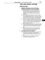
Cushion
Retainer
Insulator
Follow Spring
Retainer
Cushion
Retainer
Shock Absorber
F Bushing
Breather
Hose
N·m (kgf·cm, ft·lbf) : Specified torque
F Non-reusable part
Coil Spring
Retainer
F
F
F
Stabilizer Bar Bracket
Lateral Control Rod
F
150 (1,530, 111)
69 (704, 51)
18 (185, 13)
18 (185, 13)
98 (1,000,72)
28 (290, 21)
-SUSPENSION AND AXLE COIL SPRING AND REAR SHOCK ABSORBER
SA-171
2121Author: Date:
2004 LAND CRUISER (RM1071U)
COIL SPRING AND REAR SHOCK ABSORBER
COMPONENTS
SA16C-03
F04361
-SUSPENSION AND AXLE COIL SPRING AND REAR SHOCK ABSORBER
SA-175
2125Author: Date:
2004 LAND CRUISER (RM1071U)
DISPOSAL
DISCARD SHOCK ABSORBER
Before discarding the shock absorber, drill a hole of 2 - 3 mm
(0.079 - 0.118 in.) in diameter at the location shown in the il-
lustration to discharge the gas inside.
NOTICE:
F When drilling, chips may fly out, work carefully.
F The gas is colorless, odorless and non-poisonous.
SA16B-02
SA0627
SA-174
-SUSPENSION AND AXLE COIL SPRING AND REAR SHOCK ABSORBER
2124Author: Date:
2004 LAND CRUISER (RM1071U)
INSPECTION
INSPECT SHOCK ABSORBER
Compress and extend the shock absorber rod and check that
there is no abnormal resistance or unusual operation sounds.
If there is any abnormality, replace the shock absorber with a
new one.
NOTICE:
When disposing the shock absorber, see DISPOSAL on
page SA-175 .
SA16E-01
-SUSPENSION AND AXLE COIL SPRING AND REAR SHOCK ABSORBER
SA-177
2127Author: Date:
2004 LAND CRUISER (RM1071U)
INSTALLATION
Installation is in the reverse order of removal (See page SA-172 ).
SA16A-02
F04391
F04392
F04393
F04394
SA-172
-SUSPENSION AND AXLE COIL SPRING AND REAR SHOCK ABSORBER
2122Author: Date:
2004 LAND CRUISER (RM1071U)
REMOVAL
1. REMOVE REAR WHEELS
Torque: 131 N·m (1,340 kgf·cm, 97 ft·lbf)
2. SUPPORT REAR AXLE HOUSING WITH JACK
3. REMOVE SHOCK ABSORBER
(a) Remove the bolt and disconnect the shock absorber from
the axle housing.
Torque: 98 N·m (1,000 kgf·cm, 72 ft·lbf)
(b) Employ the same manner described above to the other
side.
(c) While holding the piston rod, remove the nut, 2 retainers,
cushion and shock absorber.
Torque: 69 N·m (704 kgf·cm, 51 ft·lbf)
(d) Remove the 2 retainers and cushion from the shock ab-
sorber.
4. DISCONNECT LH AND RH STABILIZER BAR BRACK-
ETS
Remove the 4 bolts and disconnect the LH and RH stabilizer bar
brackets.
Torque: 18 N·m (185 kgf·cm, 13 ft·lbf)
5. DISCONNECT LATERAL CONTROL ROD
Remove the nut, washer, bolt and disconnect the lateral control
rod.
Torque: 150 N·m (1,530 kgf·cm, 111 ft·lbf)
HINT:
At the time of installation, after stabilizing the suspension,
torque the nut and bolt.
6. DISCONNECT BREATHER HOSE
F04396
F04395
-SUSPENSION AND AXLE COIL SPRING AND REAR SHOCK ABSORBER
SA-173
2123Author: Date:
2004 LAND CRUISER (RM1071U)
7. REMOVE COIL SPRING
(a) Begin to lower the axle housing.
NOTICE:
Be careful not to snap the brake line and parking brake
cable.
(b) While lowering the axle housing, remove the coil spring
and insulator.
HINT:
At the time of installation, please refer to the following items.
F Check that the coil spring end is installed correctly.
F If the coil spring end is not in the correct position, reinstall
the coil spring.
(c) Remove the bolt and follow spring from the frame.
Torque: 28 N·m (290 kgf·cm, 21 ft·lbf)
SA16D-02
F05063
SST
SST
F05063
SST
SST
SA-176
-SUSPENSION AND AXLE COIL SPRING AND REAR SHOCK ABSORBER
2126Author: Date:
2004 LAND CRUISER (RM1071U)
REPLACEMENT
1. REMOVE BUSHING
Using SST and a press, remove the bushing.
SST 09710-14013 (09710-00061),
09710-28012 (09710-07031),
09950-70010 (09951-07100)
2. INSTALL BUSHING
Using SST and a press, install a new bushing.
SST 09710-14013 (09710-00061),
09710-28012 (09710-07031),
09950-70010 (09951-07100)
SA168-05
Z15220
FIPG Width Approx.
1 - 2 mm (0.04 - 0.08 in.)
F05081
Adhesive
F05082
Z15219
FIPG Width Approx.
1 - 2 mm (0.04 - 0.08 in.)
-SUSPENSION AND AXLE DIFFERENTIAL LOCKING SYSTEM
SA-169
2119A uthor: Date:
2004 LAND CRUISER (RM1071U)
INSTALLATION
1. INSTALL ACTUATOR
(a) Clean contacting surfaces of any FIPG material using
gasoline or alcohol.
(b) Apply FIPG to the actuator.
FIPG:
Part No. 08826-00090, THREE BOND 1281
or equivalent
HINT:
Install the actuator within 10 minutes after applying FIPG.
(c) Install the actuator to the differential and match the shaft
with the shaft fork hole.
(d) Clean the threads of the set bolt and shaft fork with the
white gasoline.
(e) Coat the threads of the set bolt with adhesive.
Adhesive:
Part No. 08833-00070, THREE BOND 1324
or equivalent
(f) Tighten the shift fork set bolt.
Torque: 20 N·m (200 kgf·cm, 15 ft·lbf)
(g) Tighten the 4 bolts uniformly, a little at time.
Torque: 24 N·m (240 kgf·cm, 18 ft·lbf)
2. INSTALL COVER
(a) Clean the contacting surfaces of any FIPG material using
gasoline or alcohol.
(b) Apply FIPG to the cover.
FIPG:
Part No. 08826-00090, THREE BOND 1281
or equivalent
HINT:
Install the cover within 10 minutes after applying FIPG.
SA-170
-SUSPENSION AND AXLE DIFFERENTIAL LOCKING SYSTEM
2120A uthor: Date:
2004 LAND CRUISER (RM1071U)
(c) Install the cover with the 3 bolts.
Torque: 18 N·m (185 kgf·cm, 13 ft·lbf)
3. INSTALL REAR DIFF. LOCK POSITION SWITCH
Install the diff. lock position switch with a new gasket.
Torque: 40 N·m (410 kgf·cm, 30 ft·lbf)
4. CONNECT CONNECTORS AND TUBE
HINT:
F The depth of the insertion of the bleeder tube into the
hose is approx. 15 mm (0.59 in.).
F Take care that the water or the equivalent will not adhere
to the connectors and hose.
5. INSTALL NO. 2 ACTUATOR PROTECTOR
Install the No. 2 actuator protector with the 2 nuts.
Torque: 36 N·m (367 kgf·cm, 27 ft·lbf)
6. INSTALL NO. 1 ACTUATOR PROTECTOR
Install the No. 1 actuator protector with the nut and bolt.
Torque: 15 N·m (150 kgf·cm, 11 ft·lbf)
7. CANCEL REAR DIFFERENTIAL LOCK POSITION
(a) Connect the cable to the negative terminal of the battery.
(b) Turn the ignition switch to the ON position.
(c) Turn the differential lock control switch to the OFF position
and cancel the differential lock.
(d) Shift the transfer shift lever to H position.
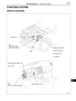
SA166-05
F05440
Differential Lock Control Switch
Combination Meter
Rear Diff. Lock Control ECU
Rear Differential Lock Position Switch
L Position Switch
Rear Differential Lock Actuator
-SUSPENSION AND AXLE DIFFERENTIAL LOCKING SYSTEM
SA-167
2117A uthor: Date:
2004 LAND CRUISER (RM1071U)
LOCATION
F05176
SA165-06
Z16659
M1 M2
-SUSPENSION AND AXLE DIFFERENTIAL LOCKING SYSTEM
SA-163
2113A uthor: Date:
2004 LAND CRUISER (RM1071U)
DIFFERENTIAL LOCKING SYSTEM
ON-VEHICLE INSPECTION
1. INSPECT DIFFERENTIAL LOCK SYSTEM
(a) Inspect the indicator light.
Check that the indicator light lights up for approx. 1 se-
cond when the ignition switch is turned ON.
(b) Inspect the differential lock operation.
(1) Jack up the vehicle then start the engine.
(2) Shift the transfer shift lever to L position.
(3) When the diff. lock control switch is set to the RR
position, the indicator light is turned on.
Differential lock is applied to the rear wheel at this
time.
HINT:
If the gears of the differential lock system are not meshed, the
indicator light remains blinking, so rotate the tires to mesh the
gear.
(4) When the diff. lock control switch is at the OFF posi-
tion, the indicator light goes off.
Differential lock is released for the rear wheel at this
time.
(5) Check the voltage between the terminals of the rear
diff. lock control ECU when switching the diff. lock
control switch with the speedometer, registering
approx. 8 km/h (5 mph) or more.
Swith position Terminal Specified value
ON M1 - M2
0.5 V or less
(No change)
(6) Return the diff. lock control switch to OFF.
(7) Stop the engine and lower the vehicle.
2. INSPECT DIFF. LOCK SYSTEM CIRCUIT
(a) Inspect the battery positive voltage.
Battery positive voltage: 10 - 14 V
Z16462
RLP RM1M2
4WD
GND SPDIG
Wire harness:
Z16461
GND
4WD
RLPM1
M2
ECU:
SA-164
-SUSPENSION AND AXLE DIFFERENTIAL LOCKING SYSTEM
2114A uthor: Date:
2004 LAND CRUISER (RM1071U)
(b) Inspect the system circuit with the connector discon-
nected.
Disconnect the connector from the rear diff. lock control
ECU and inspect the connector on the wire harness side,
as shown in the table.
Symbols (Terminals No.) Trouble part Condition Specified value
M1 - M2 RR Diff. Lock Actuator - Less than 100 Ω
GND - Body ground Body ground - Continuity
SPD - Body ground Speed sensor Vehicle moves slowly
1 pulse each
40 cm (15.75 in.)
IG - Body ground DIFF Fuse Ignition switch ON 10 - 14 V
RLP B d d
Rear Diff. Lock Indica-
Ignition switch ON with indicator light ON About 0 V
RLP - Body ground
Rear
Diff
.
Lock
Indica
tor Switch
Ignition switch ON with indicator light OFF 10 - 14 V
4WD B d d
L iti S it h
Ignition switch ON with T/F shift lever except L About 0 V
4WD - Body ground L position Switch
Ignition switch ON with T/F shift lever L 10 - 14 V
RBd d
Differential Lock Con-
Ignition switch ON with differential lock control switch RR 10 - 14 V
R - Body ground
Differential
Lock
Con
trol Switch
Ignition switch ON with differential lock control switch OFF About 0 V
HINT:
If the circuit is not as specified value, check and repair or re-
place the trouble part shown in the table above.
(c) Inspect the system circuit with the connector connected.
(1) Turn the ignition switch to the ON position.
(2) Shift the transfer shift lever to L position.
(3) Using a voltmeter, measure the voltage when the
differential lock control switch is in the position, as
shown in the table.
Tester Connection
ę - Ĝ
Switch position Specified valve
4WD - GND - 10 - 14 V
RLP - GND RR* 0.5 V or less
M1 - M2 OFF → RR
0.5 V or less → 10 - 14 V
(A 1 ) 05V
M2 - M1 RR → OFF
(Approx. 1 sec.) → 0.5 V
or less
*: The rear differential should be locked mechanically.
If the circuit is not as specified value, replace the ECU.
(4) Install the ECU in place.
W02075
1
2
3
45
Relay Housing
Metallic Parts
Heater main relay:
Z07257
Free → Lock Lock → Free
Heater Main
Relay
Battery Battery
Heater Main
Relay
1
2
3
4
5
1
2
3
4
5
5
23
4
6
23
4
F05957
1
4
(+)
(-)
F05962
-SUSPENSION AND AXLE DIFFERENTIAL LOCKING SYSTEM
SA-165
2115A uthor: Date:
2004 LAND CRUISER (RM1071U)
3. INSPECT DIFF. LOCK COMPONENTS
(a) Inspect the relay operation.
(1) Jack up the vehicle.
(2) Use a heater main relay and connect it, as shown
below.
NOTICE:
Connect the terminals being careful not to touch the neigh-
boring terminals or metallic parts of the relay housing.
(3) Rotate the tire and check that differential lock has
occurred.
If operation is not as specified, replace the actuator.
(b) Inspect the diff. lock control switch continuity.
Inspect the switch continuity between terminal 1 to termi-
nal 4.
HINT:
If continuity dose not exist, replace the switch.
(c) Inspect the diff. lock indicator switch.
(1) Check that continuity between exists terminals
when the switch is pushed (differential connected
position).
(2) Check that no continuity exists when the switch is
free (differential disconnected position).
HINT:
If operation is not as specified, replace the switch.
SA-166
-SUSPENSION AND AXLE DIFFERENTIAL LOCKING SYSTEM
2116A uthor: Date:
2004 LAND CRUISER (RM1071U)
(d) Inspect the L position switch (See page TR-49 ).
(e) Inspect the vehicle speed sensor (See page BE-63 ).
SA167-05
F05181
F05083
F04360
SA-168
-SUSPENSION AND AXLE DIFFERENTIAL LOCKING SYSTEM
2118A uthor: Date:
2004 LAND CRUISER (RM1071U)
REMOVAL
1. SHIFTING REAR DIFF. LOCK POSITION
(a) Turn the ignition switch to the ON position.
(b) Shift the transfer shift lever to L position.
(c) Turn the differential lock control switch to the RR position
and lock the rear differential.
HINT:
While rotating the rear wheels, check they are in the differential
lock condition.
(d) Disconnect the cable from the negative terminal of the
battery.
2. REMOVE NO. 1 ACTUATOR PROTECTOR
Remove the nut, bolt and No. 1 actuator protector.
3. REMOVE NO. 2 ACTUATOR PROTECTOR
Remove the 2 nuts and No. 2 actuator protector.
4. DISCONNECT CONNECTORS AND TUBE
5. REMOVE REAR DIFF. LOCK POSITION SWITCH
6. REMOVE COVER
(a) Remove the 3 bolts.
(b) Using a brass bar and hammer, remove the cover.
7. REMOVE ACTUATOR
(a) Remove the shift fork set bolt.
(b) Remove the 4 bolts.
(c) Using a screwdriver, pry out the actuator.
SA143-04
F05256
123 (1,250, 91)
74 (750, 54)
Disc
F Bearing
F Oil Seal
F Bearing
F Lock Washer
F Gasket
F Snap Ring
Axle Hub
Hub Bolt
Claw Washer
Adjusting Nut
Lock Nut
Flange
F Grease Cap
33 (335, 24)
Brake Caliper
x6
F Non-reusable part
N·m (kgf·cm, ft·lbf) : Specified torque
x5
28 (290, 21)
F
Cone Washer
64 (650, 47)
Flexible Hose
See Page SA-16
-SUSPENSION AND AXLE FRONT AXLE HUB
SA-1 1
1961Author: Date:
2004 LAND CRUISER (RM1071U)
FRONT AXLE HUB
COMPONENTS
SA145-04
F04408
F04339
F04340
Matchmarks
-SUSPENSION AND AXLE FRONT AXLE HUB
SA-13
1963Author: Date:
2004 LAND CRUISER (RM1071U)
DISASSEMBLY
1. REMOVE OIL SEAL AND BEARING
(a) Using a screwdriver, pry out the oil seal.
(b) Remove the bearing from the axle hub.
2. REMOVE BEARING OUTER RACES
(a) Using a brass bar and hammer, remove the outside bear-
ing outer race.
NOTICE:
Be careful not to damage the ABS speed sensor rotor.
(b) Using a brass bar and hammer, remove the inside bearing
outer race.
3. INSPECT BEARINGS
Clean the bearings and outer races and inspect them for wear
or damage.
4. REMOVE DISC
(a) Mount the axle hub with the disc in a soft jaw vice.
NOTICE:
Close vice until it holds disc, do not tighten further.
(b) Place matchmarks on the axle hub and disc.
(c) Remove the 5 bolts and separate the axle hub and disc.
SA147-09
F04370
SST
F04362
90°
F04370
SST
SA-16
-SUSPENSION AND AXLE FRONT AXLE HUB
1966Author: Date:
2004 LAND CRUISER (RM1071U)
INSTALLATION
1. INSTALL AXLE HUB TO STEERING KNUCKLE
(a) Place the axle hub with disc to the steering knuckle.
NOTICE:
Be careful not to damage the ABS speed sensor rotor and
oil seal.
(b) Install the outer bearing.
(c) Install the claw washer.
2. ADJUST PRELOAD
(a) Install the adjusting nut and using SST, tighten it.
SST 09607-60020
Torque: 59 N·m (600 kgf·cm, 43 ft·lbf)
(b) Turn the axle hub several times to settle down the bear-
ing.
(c) Using SST, loosen the adjusting nut until it can rotate by
hand.
SST 09607-60020
(d) Using SST, retighten the adjusting nut.
SST 09607-60020
Torque: 4.3 - 6.5 N·m (44 - 66 kgf·cm, 38 - 57 in.·lbf)
HINT:
Check that there is no looseness on the bearing.
(e) Using a spring tension gauge, measure the preload.
Preload (at starting):
42 - 67 N (4.3 - 6.8 kgf, 9.5 - 15.0 lbf)
3. INSTALL LOCK WASHER AND LOCK NUT
(a) Install a new lock washer and the lock nut.
(b) Using SST, torque the lock nut.
SST 09607-60020
Torque: 64 N·m (650 kgf·cm, 47 ft·lbf)
(c) Check that the axle hub rotates smoothly and there is no
looseness on the bearing.
F04362
90°
F04363
-SUSPENSION AND AXLE FRONT AXLE HUB
SA-17
1967Author: Date:
2004 LAND CRUISER (RM1071U)
(d) Using a spring tension gauge, check the preload.
Preload (at starting):
42 - 67 N (4.3 - 6.8 kgf, 9.5 - 15.0 lbf)
HINT:
Make sure to check preload in the direction of rotation.
If the preload is not within the specified value, adjust it again
with the adjusting nut.
(e) Secure the lock nut by bending one of the lock washer
teeth inward and the other lock washer teeth outward.
4. INSTALL FLANGE
(a) Place a new gasket in position on the axle hub.
(b) Install the flange to the axle hub.
(c) Install the 6 cone washers, washers and new nuts.
Torque: 33 N·m (335 kgf·cm, 24 ft·lbf)
(d) Pull out the drive shaft to the outside of the vehicle and
select the snap ring which ensures the clearance be-
tween the tip of the flange and the snap ring is less than
0.2 mm (0.008 in.).
Snap ring thickness:
1.8 mm (0.0709 in.) 2.4 mm (0.0945 in.)
2.0 mm (0.0787 in.) 2.6 mm (0.1024 in.)
2.2 mm (0.0866 in.) 2.8 mm (0.1102 in.)
(e) Using a snap ring expander, install a new snap ring to the
drive shaft.
(f) Install a new grease cap to the flange.
5. INSTALL BRAKE CALIPER
(a) Install the brake caliper, washers and 2 bolts.
Torque: 123 N·m (1,250 kgf·cm, 91 ft·lbf)
(b) Install the flexible hose and bolt to the steering knuckle.
Torque: 28 N·m (290 kgf·cm, 21 ft·lbf)
6. INSTALL FRONT WHEEL
Torque: 131 N·m (1,340 kgf·cm, 97 ft·lbf)
7. CHECK ABS SPEED SENSOR SIGNAL
(See page DI-505 )
SA146-04
F04340
Matchmarks
F04341
SST
F04342
SST
RA0009
SA0412
MP Grease
SA-14
-SUSPENSION AND AXLE FRONT AXLE HUB
1964Author: Date:
2004 LAND CRUISER (RM1071U)
REASSEMBLY
1. INSTALL DISC
(a) Mount the disc in a soft jaw vice.
NOTICE:
Close vice until it holds disc, do not tighten further.
(b) Align the matchmarks on the axle hub and disc.
(c) Install the 5 bolts to the axle hub.
Torque: 74 N·m (750 kgf·cm, 54 ft·lbf)
2. INSTALL BEARING OUTER RACES
(a) Using SST and a hammer, carefully install a new outside
bearing outer race.
SST 09950-60020 (09951-00730),
09950-70010 (09951-07100)
(b) Using SST and a hammer, carefully install a new inside
bearing outer race.
SST 09950-60020 (09951-00890),
09950-70010 (09951-07100)
NOTICE:
Be careful not to damage the ABS speed sensor rotor.
3. PACK BEARING WITH MP GREASE
(a) Place MP grease in the palm of your hand.
(b) Pack grease into a new bearing, continuing until the
grease oozes out from the other side.
(c) Employ the same manner around the bearing circumfer-
ence.
4. COAT INSIDE OF AXLE HUB WITH MP GREASE
5. INSTALL INNER BEARING AND OIL SEAL
(a) Place the inner bearing into the axle hub.
F04343
SST
-SUSPENSION AND AXLE FRONT AXLE HUB
SA-15
1965Author: Date:
2004 LAND CRUISER (RM1071U)
(b) Using SST and a hammer, install a new oil seal into the
axle hub.
SST 09950-60020 (09951-01030),
09950-70010 (09951-07100)
NOTICE:
Be careful not to damage the ABS speed sensor rotor.
(c) Coat the lip of the oil seal with MP grease.
SA144-04
F04367
F04368
F04369
F04370
SST
SA-12
-SUSPENSION AND AXLE FRONT AXLE HUB
1962Author: Date:
2004 LAND CRUISER (RM1071U)
REMOVAL
1. REMOVE FRONT WHEEL
2. REMOVE BRAKE CALIPER
(a) Remove the bolt and disconnect the flexible hose from
the steering knuckle.
(b) Remove the 2 bolts, washers and brake caliper.
(c) Support the brake caliper securely.
3. REMOVE FLANGE
(a) Using a screwdriver and hammer, remove the grease cap
from the flange.
(b) Using a snap ring expander, remove the snap ring.
(c) Remove the 6 nuts and washers.
(d) Install the 6 nuts temporarily to protect the threads of the
stud bolts.
(e) Using a brass bar and hammer, tap on the bolt heads and
remove the 6 nuts and cone washers.
(f) Remove the flange and gasket.
4. REMOVE AXLE HUB WITH DISC
(a) Using a screwdriver, release the lock washer.
(b) Using SST, remove the lock nut.
SST 09607-60020
(c) Remove the lock washer.
(d) Using SST, remove the adjusting nut.
SST 09607-60020
(e) Remove the axle hub with disc.
NOTICE:
Be careful not to damage the ABS speed sensor rotor and
oil seal.
(f) Remove the claw washer and bearing from the axle hub.
SA1SE-01
F05442
f Grease Cap
Steering Knuckle Arm
f Cotter Pin
Drive Shaft
N·m (kgf·cm, ft·lbf)
f Snap Ring
Steering Knuckle with
Axle Hub
Brake Caliper
ABS Speed Sensor
and Wire Harness
f Cotter Pin
: Specified torque
f Non-reusable part
F Precoated part
28 (290, 21)
13 (130, 10)
8.0 (82, 71 in.·lbf)
110 (1,125, 81)
159 (1,625, 117)
147 (1,500, 108)
123 (1,250, 91)
28 (290, 21)
F
f Snap Ring
SA-36
-SUSPENSION AND AXLE FRONT DIFFERENTIAL CARRIER
1986Author: Date:
2004 LAND CRUISER (RM1071U)
FRONT DIFFERENTIAL CARRIER
COMPONENTS
F05231
N·m (kgf·cm, ft·lbf) : Specified torque
Propeller Shaft
Differential
Support
Mount Stopper
Differential Carrier
Assembly
Breather Hose
No. 3 Frame
Crossmember
Mount Stopper
Mount Stopper
Mount
Stopper
Differential Support
186 (1,900, 137)
17 (173, 13)
78 (800, 58)
68 (695, 50)
68 (695, 50)
186 (1,900, 137)
186 (1,900, 137)
186 (1,900, 137)
80 (820, 59)
-SUSPENSION AND AXLE FRONT DIFFERENTIAL CARRIER
SA-37
1987Author: Date:
2004 LAND CRUISER (RM1071U)
F11449
Rear Bearing
Oil Slinger
Companion Flange
See page SA-47
f
f Oil Seal
f Bearing Spacer
f Oil Storage Ring
Dust Deflector
F
105 (1,070, 77)
Differential Tube
49 (500, 36)
Filler Plug
f Gasket
49 (500, 36)
Drain Plug
f Gasket
Washer
Differential Carrier
f
Drive Pinion
Front Bearing
Breather Plug
Oil Deflector
7.3 (74, 64 in.·lbf)
Differential
Carrier Cover
47 (475, 34)
x8
Thrust Washer
Side Gear
Spider
Pinion Gear
Thrust Washer
Pinion Gear
N·m (kgf·cm, ft·lbf) : Specified torque
f Non-reusable part
F Precoated part
Side Gear Shaft
Bearing
Snap Ring
f Oil Seal
x10
x5
LH Differential Case
Ring Gear
Plate Washer
Bearing Cap
85 (870, 63)
97 (985, 71)
x8
Side Bearing
RH Differential Case
SA-38
-SUSPENSION AND AXLE FRONT DIFFERENTIAL CARRIER
1988Author: Date:
2004 LAND CRUISER (RM1071U)