hệ thống điều khiển động cơ trang 152 279 trên xe matiz đời 2000 - 2013
Bạn đang xem bản rút gọn của tài liệu. Xem và tải ngay bản đầy đủ của tài liệu tại đây (730.87 KB, 128 trang )
1F–152 ENGINE CONTROLS
DAEWOO M-150 BL2
MAA1F180
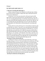
DIAGNOSTIC TROUBLE CODE (DTC) – P0336 58X CRANKSHAFT POSITION
SENSOR NO PLAUSIBLE SIGNAL
Circuit Description
The 58X reference signal is produced by the crankshaft
position (CKP) sensor. During one crankshaft revolu-
tion, 58 crankshaft pulses will be produced. The engine
control module(ECM) uses the 58X reference signal to
calculate engine rpm and CKP. The ECM constantly
monitors the number of pulses on the 58X reference cir-
cuit and compares them to the number of camshaft posi-
tion (CKP) signal pulses being received. If the ECM
receive and incorrect number of pulses on the 58X refer-
ence circuit, DTC P0336 will set.
Conditions for Setting the DTC
D This DTC can be stored in “key-on” status.
D Detected number of teeth is differs by 3 or higher.
Action Taken When the DTC Sets
D The Malfunction Indicator Lamp (MIL) will illuminate.
D The ECM will record operating conditions at the time
the diagnostic fails. This information will be stored in
the Freeze Frame and Failure Records buffers.
D A history DTC is stored.
Conditions for Clearing the MIL/DTC
D The MIL will turn off after four consecutive ignition
cycles in which the diagnostic runs without a fault.
D A history DTC will clear after 40 consecutive warm-up
cycles without a fault.
D DTC(s) can be cleared by using the scan tool.
D Disconnecting the ECM battery feed for more than 10
seconds.
DIAGNOSTIC AIDS
An intermittent may be caused by a poor connection,
rubbed-through wire insulation or a wire broken inside
the insulation. Check for :
Poor connection – inspect the ECM harness and con-
nectors for improper mating, broken locks, improperly
formed or damaged terminals, and poor terminal-to-wire
connection.
Damaged harness – inspect the wiring harness for dam-
age. If the harness appears to be OK, disconnect the
ECM, turn the ignition ON and observe a voltmeter con-
nected to the 58X reference circuit at the ECM harness
connector while moving the connectors and the wiring
harness related to the ECM. A change in voltage will in-
dicate the location of the fault.
Review the failure records vehicle mileage since the
diagnostic test failed may help determine how often the
condition that caused the DTC to be set occurs. This
may assist in diagnosing the condition.
ENGINE CONTROLS 1F–153
DAEWOO M-150 BL2
DTC P0336 – 58X Crankshaft Position Sensor No Plausible Signal
Step Action Value(s) Yes No
1
Perform an Euro On-Board Diagnostic (EOBD)
System Check.
Is the system check complete?
–
Go to Step 2
Go to
“On-Board
Diagnostic
System Check”
2
Attempt to start the engine.
Does the engine start?
–
Go to Step 3
Refer to
“Engine
Cranks But
Will Not Run”
3
1. Review and record Failure Records information.
2. Clear the DTC P0336.
3. Start the engine and idle for 1 minute.
4. Observe the diagnostic trouble codes (DTCs).
Is the DTC P0336 set?
–
Go to Step 4
Go to
“Diagnostic
Aids”
4
1. Disconnect the engine control module(ECM) and
the crankshaft position (CKP) sensor.
2. Check for an open or a low voltage in the CKP
sensor connector and the ECM harness
connector.
Is the problem found?
–
Go to Step 5 Go to Step 6
5
Repair the open or low voltage in the 58X reference
circuit between the CKP sensor connector and the
ECM harness connector.
Is the repair complete?
–
Go to Step 11
–
6
1. Reconnect the ECM and CKP sensor.
2. Connect a digital voltmeter (DVM) to measure
voltage on the 58X reference circuit, terminal 54
at the ECM connector.
3. Observe the voltage while cranking the engine.
Is the voltage near the specified value? 2.5V Go to Step 9 Go to Step 7
7
Check the connection at the CKP sensor and
replace the terminals if necessary.
Do any terminals require replacement?
–
Go to Step 11 Go to Step 8
8
Replace the CKP sensor.
Is the replacement complete?
–
Go to Step 11
–
9
Check the connections at the ECM and replace the
terminals if necessary.
Do any terminal require replacement?
–
Go to Step 11 Go to Step 10
10
Replace the ECM.
Is the replacement complete?
–
Go to Step 11
–
11
1. Using the scan tool, clear the DTCs.
2. Start the engine and idle at normal operating
temperature.
3. Operate the vehicle within the conditions for
setting this DTC as specified in the supporting
text.
Does the scan tool indicate that this diagnostic run
and passed?
–
Go to Step 12 Go to Step 2
12
Check if any additional DTCs are set.
Are any DTCs displaced that have not been
diagnosed?
–
Go to
Applicable DTC
table
System OK
1F–154 ENGINE CONTROLS
DAEWOO M-150 BL2
MAA1F180
DIAGNOSTIC TROUBLE CODE (DTC) – P0337 58X CRANKSHAFT POSITION
SENSOR NO SIGNAL
Circuit Description
The 58X reference signal is produced by the crankshaft
position (CKP) sensor. During one crankshaft revolu-
tion, 58 crankshaft pulses will be produced. The engine
control module(ECM) uses the 58X reference signal to
calculate engine rpm and CKP. The ECM constantly
monitors the number of pulses on the 58X reference cir-
cuit and compares them to the number of camshaft posi-
tion (CKP) signal pulses being received. If the ECM
receive and incorrect number of pulses on the 58X refer-
ence circuit, DTC P0337 will set.
Conditions for Setting the DTC
D This DTC can be stored in “key-on” status.
D No crankshaft teeth detected.
Action Taken When the DTC Sets
D The Malfunction Indicator Lamp (MIL) will illuminate.
D The ECM will record operating conditions at the time
the diagnostic fails. This information will be stored in
the Freeze Frame and Failure Records buffers.
D A history DTC is stored.
Conditions for Clearing the MIL/DTC
D The MIL will turn off after four consecutive ignition
cycles in which the diagnostic runs without a fault.
D A history DTC will clear after 40 consecutive warm-up
cycles without a fault.
D DTC(s) can be cleared by using the scan tool.
DIAGNOSTIC AIDS
An intermittent may be caused by a poor connection,
rubbed-through wire insulation or a wire broken inside
the insulation. Check for :
Poor connection – inspect the ECM harness and con-
nectors for improper mating, broken locks, improperly
formed or damaged terminals, and poor terminal-to-wire
connection.
Damaged harness – inspect the wiring harness for dam-
age. If the harness appears to be OK, disconnect the
ECM, turn the ignition ON and observe a voltmeter con-
nected to the 58X reference circuit at the ECM harness
connector while moving the connectors and the wiring
harness related to the ECM. A change in voltage will in-
dicate the location of the fault.
Review the failure records vehicle mileage since the
diagnostic test failed may help determine how often the
condition that caused the DTC to be set occurs. This
may assist in diagnosing the condition.
ENGINE CONTROLS 1F–155
DAEWOO M-150 BL2
DTC P0337 – 58X Crankshaft Position Sensor No Signal
Step Action Value(s) Yes No
1
Perform an Euro On-Board Diagnostic (EOBD)
System Check.
Is the system check complete?
–
Go to Step 2
Go to
“On-Board
Diagnostic
System Check”
2
Attempt to start the engine.
Does the engine start?
–
Go to Step 3
Refer to
“Engine
Cranks But
Will Not Run”
3
1. Review and record Failure Records information.
2. Clear the DTC P0337.
3. Start the engine and idle for 1 minute.
4. Observe the diagnostic trouble codes (DTCs).
Is the DTC P0337 set?
–
Go to Step 4
Go to
“Diagnostic
Aids”
4
1. Disconnect the engine control module(ECM) and
the crankshaft position (CKP) sensor.
2. Check for an open or a low voltage in the CKP
sensor connector and the ECM harness
connector.
Is the problem found?
–
Go to Step 5 Go to Step 6
5
Repair the open or low voltage in the 58X reference
circuit between the CKP sensor connector and the
ECM harness connector.
Is the repair complete?
–
Go to Step 11
–
6
1. Reconnect the ECM and CKP sensor.
2. Connect a digital voltmeter (DVM) to measure
voltage on the 58X reference circuit, terminal 54
at the ECM connector.
3. Observe the voltage while cranking the engine.
Is the voltage near the specified value? 2.5V Go to Step 9 Go to Step 7
7
Check the connection at the CKP sensor and
replace the terminals if necessary.
Do any terminals require replacement?
–
Go to Step 11 Go to Step 8
8
Replace the CKP sensor.
Is the replacement complete?
–
Go to Step 11
–
9
Check the connections at the ECM and replace the
terminals if necessary.
Do any terminal require replacement?
–
Go to Step 11 Go to Step 10
10
Replace the ECM.
Is the replacement complete?
–
Go to Step 11
–
11
1. Using the scan tool, clear the DTCs.
2. Start the engine and idle at normal operating
temperature.
3. Operate the vehicle within the conditions for
setting this DTC as specified in the supporting
text.
Does the scan tool indicate that this diagnostic run
and passed?
–
Go to Step 12 Go to Step 2
12
Check if any additional DTCs are set.
Are any DTCs displaced that have not been
diagnosed?
–
Go to
Applicable DTC
table
System OK
1F–156 ENGINE CONTROLS
DAEWOO M-150 BL2
MAA1F190
DIAGNOSTIC TROUBLE CODE (DTC) – P0341 CAMSHAFT POSITION SENSOR
RATIONALITY
Circuit Description
The Camshaft Position Sensor is used to detect Cam-
shaft position and to have correlation with Crankshaft
position so that the ECM can determine which cylinder is
ready to be fueled by the injector. The polarity of cam-
shaft sensor signal must be changed only once per
crankshaft position.
Conditions for Setting the DTC
D Engine is running.
D No traction of CMP signal between teeth 18 and 82
but change in polarity.
Action Taken When the DTC Sets
D The Malfunction Indicator Lamp (MIL) will illuminate.
D The ECM will record operating conditions at the time
the diagnostic fails. This information will be stored in
the Freeze Frame and Failure Records buffers.
D A history DTC is stored.
Conditions for Clearing the MIL/DTC
D The MIL will turn off after four consecutive ignition
cycles in which the diagnostic runs without a fault.
D A history DTC will clear after 40 consecutive warm-up
cycles without a fault.
D DTC(s) can be cleared by using the scan tool.
Diagnostic Aids
Check and correct any abnormal engine noise before
using the diagnostic table.
Any circuitry that is suspected as causing engine noise
complaint should be thoroughly checked for the follow-
ing conditions :
D Backed-out terminals.
D Improper mating.
D Broken locks.
D Improperly formed.
D Damaged terminals.
D Poor terminal-to-wire connections.
D Physical damage to the wiring harness.
ENGINE CONTROLS 1F–157
DAEWOO M-150 BL2
DTC P0341 – Camshaft Position Sensor Rationality
Step Action Value(s) Yes No
1
Perform an Euro On-Board Diagnostic (EOBD)
System Check.
Is the system check complete?
–
Go to Step 2
Go to
“On-Board
Diagnostic
System Check”
2
1. Turn the ignition switch to LOCK.
2. Disconnect the CMP sensor connector.
3. Check for a faulty connector or terminals.
Is the problem found?
–
Go to Step 4 Go to Step 3
3
1. Turn the ignition switch to ON.
2. Disconnect the ECM connector.
3. Inspect the ECM pins and connector for bent or
damaged terminals.
4. Check the wire between the CMP sensor terminal
1 and ECM connector 82 for an open or short to
ground or short to battery voltage while related
connectors and wiring harness.
5. Check the wires between the CMP sensor
terminal 2 and ECM connector 18 for an open
while moving related connectors and wiring
harness.
Is the problem found?
–
Go to Step 4 Go to Step 5
4
1. Turn the ignition switch to LOCK.
2. Repair or replace the wire or the connector.
3. Clear any DTCs from the ECM.
4. Run the engine.
5. Perform the diagnostic system check.
Is the repair complete?
–
System OK
–
5
1. Turn the ignition switch to LOCK.
2. Replace the CMP sensor.
3. Clear any DTCs from the ECM.
4. Run the engine.
5. Perform the diagnostic system check.
Does DTC P0341 reset?
–
System OK Go to Step 6
6
1. Replace the ECM.
2. Run the engine.
3. Perform the Diagnostic system check.
Is the replacement complete?
–
Go to Step 7
–
7
1. Using the scan tool, clear the DTCs.
2. Start the engine and idle at normal operating
temperature.
3. Operate the vehicle within the conditions for
setting this DTC as specified in the supporting
text.
Does the scan tool indicate that this diagnostic run
and passed?
–
Go to Step 8
–
8
Check if any additional DTCs are set.
Are any DTCs displayed that have not been
diagnosed?
–
Go to
Applicable DTC
table
System OK
1F–158 ENGINE CONTROLS
DAEWOO M-150 BL2
MAA1F190
DIAGNOSTIC TROUBLE CODE (DTC) – P0342 CAMSHAFT POSITION SENSOR
NO SIGNAL
Circuit Description
The Camshaft Position Sensor is used to detect Cam-
shaft position and to have correlation with Crankshaft
position so that the ECM can determine which cylinder is
ready to be fueled by the injector. The polarity of cam-
shaft sensor signal must be changed only once per
crankshaft position.
Conditions for Setting the DTC
D Engine is running.
D No traction of CMP signal between teeth 18 and 82
but change in polarity.
Action Taken When the DTC Sets
D The Malfunction Indicator Lamp (MIL) will illuminate.
D The ECM will record operating conditions at the time
the diagnostic fails. This information will be stored in
the Freeze Frame and Failure Records buffers.
D A history DTC is stored.
Conditions for Clearing the MIL/DTC
D The MIL will turn off after four consecutive ignition
cycles in which the diagnostic runs without a fault.
D A history DTC will clear after 40 consecutive warm-up
cycles without a fault.
D DTC(s) can be cleared by using the scan tool.
DIAGNOSTIC AIDS
Check and correct any abnormal engine noise before
using the diagnostic table.
Any circuitry that is suspected as causing engine noise
complaint should be thoroughly checked for the follow-
ing conditions :
D Backed-out terminals.
D Improper mating.
D Broken locks.
D Improperly formed.
D Damaged terminals.
D Poor terminal-to-wire connections.
D Physical damage to the wiring harness.
ENGINE CONTROLS 1F–159
DAEWOO M-150 BL2
DTC P0342 – Camshaft Position Sensor No Signal
Step Action Value(s) Yes No
1
Perform an Euro On-Board Diagnostic (EOBD)
System Check.
Is the system check complete?
–
Go to Step 2
Go to
“On-Board
Diagnostic
System Check”
2
1. Turn the ignition switch to LOCK.
2. Disconnect the CMP sensor connector.
3. Check for a faulty connector or termin1als.
Is the problem found?
–
Go to Step 4 Go to Step 3
3
1. Turn the Turn the ignition switch to ON.
2. Disconnect the ECM connector.
3. Inspect the ECM pins and connector for bent or
damaged terminals.
4. Check the wire between the CMP sensor terminal
1 and ECM connector 82 for an open or short to
ground or short to battery voltage while related
connectors and wiring harness.
5. Check the wires between the CMP sensor
terminal 2 and ECM connector 18 for an open
while moving related connectors and wiring
harness.
Is the problem found?
–
Go to Step 4 Go to Step 5
4
1. Turn the ignition switch to LOCK.
2. Repair or replace the wire or the connector.
3. Clear any DTCs from the ECM.
4. Run the engine.
5. Perform the diagnostic system check.
Is the repair complete?
–
System OK
–
5
1. Turn the ignition switch to LOCK.
2. Replace the CMP sensor.
3. Clear any DTCs from the ECM.
4. Run the engine.
5. Perform the diagnostic system check.
Does DTC P0342 reset?
–
System OK Go to Step 6
6
1. Replace the ECM.
2. Run the engine.
3. Perform the Diagnostic system check.
Is the replacement complete?
–
Go to Step 7
–
7
1. Using the scan tool, clear the DTCs.
2. Start the engine and idle at normal operating
temperature.
3. Operate the vehicle within the conditions for
setting this DTC as specified in the supporting
text.
Does the scan tool indicate that this diagnostic run
and passed?
–
Go to Step 8
–
8
Check if any additional DTCs are set.
Are any DTCs displayed that have not been
diagnosed?
–
Go to
Applicable DTC
table
System OK
1F–160 ENGINE CONTROLS
DAEWOO M-150 BL2
MAA1F200
DIAGNOSTIC TROUBLE CODE (DTC) – P0351 IGNITION SIGNAL COIL A FAULT
Circuit Description
The engine control module (ECM) provides a ground for
the electronic spark timing 1 circuit. When the ECM re-
moves the ground path of the ignition primary coil, the
magnetic field produced by the coil collapses. The col-
lapsing magnetic field produces a voltage in the secon-
dary coil which fires the spark plug. The circuit between
the ECM and the electronic ignition system is monitored
for an open circuit, short to voltage, and low voltage.
When the ECM detects a problem in the spark timing 1
circuit, it will set DTC P0351.
Conditions for Setting the DTC
D This DTC can be stored in “key-on” status.
D Time of fault fall occurrence is greater than time of the
DIS fall occurrence.
D Must receive more than 40 failure within 80 test
cycles.
Action Taken When the DTC Sets
D The Malfunction Indicator Lamp (MIL) will illuminate.
D The ECM will record operating conditions at the time
the diagnostic fails. This information will be stored in
the Freeze Frame and Failure Records buffers.
D A history DTC is stored.
Conditions for Clearing the MIL/DTC
D The MIL will turn off after four consecutive ignition
cycles in which the diagnostic runs without a fault.
D A history DTC will clear after 40 consecutive warm-up
cycles without a fault.
ENGINE CONTROLS 1F–161
DAEWOO M-150 BL2
D DTC(s) can be cleared by using the scan tool.
D Disconnecting the ECM battery feed for more than 10
seconds.
DIAGNOSTIC AIDS
Check and correct any abnormal engine noise before
using the diagnostic table.
Any circuitry that is suspected as causing engine noise
complaint should be thoroughly checked for the follow-
ing conditions :
D Backed-out terminals.
D Improper mating.
D Broken locks.
D Improperly formed.
D Damaged terminals.
D Poor terminal-to-wire connections.
D Physical damage to the wiring harness.
DTC P0351 – Ignition Signal Coil A Fault
Step Action Value(s) Yes No
1
Perform an Euro On-Board Diagnostic (EOBD)
System Check.
Is the system check complete?
–
Go to Step 2
Go to
“On-Board
Diagnostic
System Check”
2
Check for a faulty connection or a damaged terminal
1 at the ignition coil.
Is a problem found?
–
Go to Step 8 Go to Step 3
3
Check for a faulty connection or a damaged terminal
31 at the engine control module(ECM) connector.
Is the problem found?
–
Go to Step 8 Go to Step 4
4
1. Turn the ignition switch to LOCK.
2. Disconnect the ECM.
3. Check the ignition control circuit for a short to
ground.
Is the problem found?
–
Go to Step 8 Go to Step 5
5
Check the ignition control circuit for a short to
battery voltage.
Is the problem found?
–
Go to Step 8 Go to Step 6
6
Check for an open in the ignition control.
Is the problem found?
–
Go to Step 8 Go to Step 7
7
Replace the ECM.
Is the replacement complete?
–
Go to Step 8
–
8
1. Using the scan tool, clear the Diagnostic Trouble
Codes(DTCs).
D Start the engine and Idle at normal operating
temperature.
D Operate the vehicle within the conditions for
setting this DTC as specified in the supporting
text.
Does the scan tool indicate that this diagnostic ran
and passed?
–
Go to Step 9
–
9
Check if any additional DTCs are set.
Are any DTCs displayed that have not been
diagnosed?
–
Go to
Applicable DTC
table
System OK
1F–162 ENGINE CONTROLS
DAEWOO M-150 BL2
MAA1F200
DIAGNOSTIC TROUBLE CODE (DTC) – P0352 IGNITION SIGNAL COIL B FAULT
Circuit Description
The engine control module (ECM) provides a ground for
the electronic spark timing 3 circuit. When the ECM re-
moves the ground path of the ignition primary coil, the
magnetic field produced by the coil collapses. The col-
lapsing magnetic field produces a voltage in the secon-
dary coil, which fires the spark plug. The circuit between
the ECM and the electronic ignition system is monitored
for an open circuit, short to voltage, and low voltage.
When the ECM detects a problem in the spark timing 3
circuit, it will set DTC P0352.
Conditions for Setting the DTC
D This DTC can be stored in “key-on” status.
D Time of fault fall occurrence is greater than time of the
DIS fall occurrence.
D Must receive more than 40 failure within 80 test
cycles.
Action Taken When The DTCs Sets
D The Malfunction Indicator Lamp (MIL) will illuminate.
D The ECM will record operating conditions at the time
the diagnostic fails. This information will be stored in
the Freeze Frame and failure records buffers.
D A history DTC is stored.
D The ECM will default to 6 degree timing.
Conditions for Clearing the MIL/DTC
D The MIL will turn off after four consecutive ignition
cycles in which the diagnostic runs without a fault.
ENGINE CONTROLS 1F–163
DAEWOO M-150 BL2
D A history DTC will clear after 40 consecutive warm up
cycles without a fault.
D Using the scan tool can clear DTC(s).
D Disconnecting the ECM battery feed for 10 seconds.
DIAGNOSTIC AIDS
Check and correct any abnormal engine noise before
using the diagnostic table.
Any circuitry that is suspected as causing engine noise
complaint should be thoroughly checked for the follow-
ing conditions :
D Backed-out terminals.
D Improper mating.
D Broken locks.
D Improperly formed.
D Damaged terminals.
D Poor terminal-to-wire connections.
D Physical damage to the wiring harness.
DTC P0352 – Ignition Signal Coil B Fault
Step Action Value(s) Yes No
1
Perform an Euro On-Board Diagnostic (EOBD)
System Check.
Is the system check complete?
–
Go to Step 2
Go to
“On-Board
Diagnostic
System Check”
2
Check for a faulty connection or a damaged terminal
3 at the ignition coil.
Is a problem found?
–
Go to Step 8 Go to Step 3
3
Check for a faulty connection or a damaged terminal
32 at the engine control module(ECM) connector.
Is the problem found?
–
Go to Step 8 Go to Step 4
4
1. Turn the ignition switch to LOCK.
2. Disconnect the ECM.
3. Check the ignition control circuit for a short to
ground
Is the problem found?
–
Go to Step 8 Go to Step 5
5
Check the ignition control circuit for a short to
battery voltage.
Is the problem found?
–
Go to Step 8 Go to Step 6
6
Check for an open in the ignition control.
Is the problem found?
–
Go to Step 8 Go to Step 7
7
Replace the ECM.
Is the replacement complete?
–
Go to Step 8
–
8
1. Using the scan tool, clear the Diagnostic Trouble
Codes(DTCs).
D Start the engine and Idle at normal operating
temperature.
D Operate the vehicle within the conditions for
setting this DTC as specified in the supporting
text.
Does the scan tool indicate that this diagnostic ran
and passed?
–
Go to Step 9
–
9
Check if any additional DTCs are set.
Are any DTCs displayed that have not been
diagnosed?
–
Go to
Applicable DTC
table
System OK
1F–164 ENGINE CONTROLS
DAEWOO M-150 BL2
MAA1F200
DIAGNOSTIC TROUBLE CODE (DTC) – P0353 IGNITION SIGNAL COIL C FAULT
Circuit Description
The engine control module (ECM) provides a ground for
the electronic spark timing 3 circuit. When the ECM re-
moves the ground path of the ignition primary coil, the
magnetic field produced by the coil collapses. The col-
lapsing magnetic field produces a voltage in the secon-
dary coil, which fires the spark plug. The circuit between
the ECM and the electronic ignition system is monitored
for an open circuit, short to voltage, and low voltage.
When the ECM detects a problem in the spark timing 3
circuit, it will set DTC P0352.
Conditions for Setting the DTC
D This DTC can be stored in “key-on” status.
D Time of fault fall occurrence is greater than time of the
DIS fall occurrence.
D Must receive more than 40 failure within 80 test
cycles.
Action Taken When The DTCs Sets
D The Malfunction Indicator Lamp (MIL) will illuminate.
D The ECM will record operating conditions at the time
the diagnostic fails. This information will be stored in
the Freeze Frame and failure records buffers.
D A history DTC is stored.
D The ECM will default to 6 degree timing.
Conditions for Clearing the MIL/DTC
D The MIL will turn off after four consecutive ignition
cycles in which the diagnostic runs without a fault.
ENGINE CONTROLS 1F–165
DAEWOO M-150 BL2
D A history DTC will clear after 40 consecutive warm up
cycles without a fault.
D Using the scan tool can clear DTC(s).
D Disconnecting the ECM battery feed for 10 seconds.
DIAGNOSTIC AIDS
Check and correct any abnormal engine noise before
using the diagnostic table.
Any circuitry that is suspected as causing engine noise
complaint should be thoroughly checked for the follow-
ing conditions :
D Backed-out terminals.
D Improper mating.
D Broken locks.
D Improperly formed.
D Damaged terminals.
D Poor terminal-to-wire connections.
D Physical damage to the wiring harness.
DTC P0353 – Ignition Signal Coil C Fault
Step Action Value(s) Yes No
1
Perform an Euro On-Board Diagnostic (EOBD)
System Check.
Is the system check complete?
–
Go to Step 2
Go to
“On-Board
Diagnostic
System Check”
2
Check for a faulty connection or a damaged terminal
3 at the ignition coil.
Is a problem found?
–
Go to Step 8 Go to Step 3
3
Check for a faulty connection or a damaged terminal
32 at the engine control module(ECM) connector.
Is the problem found?
–
Go to Step 8 Go to Step 4
4
1. Turn the ignition switch to LOCK.
2. Disconnect the ECM.
3. Check the ignition control circuit for a short to
ground
Is the problem found?
–
Go to Step 8 Go to Step 5
5
Check the ignition control circuit for a short to
battery voltage.
Is the problem found?
–
Go to Step 8 Go to Step 6
6
Check for an open in the ignition control.
Is the problem found?
–
Go to Step 8 Go to Step 7
7
Replace the ECM.
Is the replacement complete?
–
Go to Step 8
–
8
1. Using the scan tool, clear the Diagnostic Trouble
Codes(DTCs).
D Start the engine and Idle at normal operating
temperature.
D Operate the vehicle within the conditions for
setting this DTC as specified in the supporting
text.
Does the scan tool indicate that this diagnostic ran
and passed?
–
Go to Step 9
–
9
Check if any additional DTCs are set.
Are any DTCs displayed that have not been
diagnosed?
–
Go to
Applicable DTC
table
System OK
1F–166 ENGINE CONTROLS
DAEWOO M-150 BL2
MAA1F210
DIAGNOSTIC TROUBLE CODE (DTC) – P1382 ROUGH ROAD DATA INVALID
(NON ABS)
Circuit Description
The VR sensor is used to detecting the road situation.
By sensing difference of wheel rotation duration caused
by bumps or potholes in the road, the Engine Control
Module (ECM) can determine if the changes in crank-
shaft speed are due to engine misfire or are driveline in-
duced. If the VR sensor detects a rough road condition,
the ECM misfire detection diagnostic will be de-acti-
vated.
The VR sensor is located in front–right wheel.
Conditions for Setting the DTC
D Vehicle speed is higher than 10km/h(6.21mph).
D No Vehicle Speed Sensor error not set.
D VR sensor output signal is higher than 0.26.
D VR sensor output signal is not change for 30seconds.
Action Taken When The DTCs Sets
D The Malfunction Indicator Lamp (MIL) will not illumi-
nate.
D The ECM will store conditions which were present
when the DTC was set as Failure Records data only.
D This information will not be stored in the Freeze
Frame data.
Conditions for Clearing the MIL/DTC
D A history DTC will clear after 40 consecutive warm-up
cycles without a fault.
D DTC(s) can be cleared by using the scan tool.
D Disconnecting the ECM battery feed for more than 10
seconds.
ENGINE CONTROLS 1F–167
DAEWOO M-150 BL2
DTC P1382 – Rough Road Data Invalid (NON ABS)
Step Action Value(s) Yes No
1
Perform an Euro On-Board Diagnostic (EOBD)
System Check.
Was the check performed?
–
Go to Step 2
Go to
“On-Board
Diagnostic
System Check”
2
1. Turn the ignition ON, with engine OFF.
2. Install a scan tool to the Data Link Connector
(DLC).
3. Review and record the scan tool Failure Records
data.
4. Operate the vehicle within Failure Records
conditions as noted.
5. Using the scan tool, monitor specific Diagnostic
Trouble Code (DTC) info for DTC P1382.
Does the scan tool indicate that DTC P1382 failed?
–
Go to Step 4 Go to Step 3
3
1. Check for the following conditions and repair as
needed:
2. VR sensor seal missing or damaged.
3. VR sensor mounting flanges cracked, missing, or
incorrectly installed.
Is the repair complete?
–
Go to Step 14
Go to
“Diagnostic
Aids”
4
1. Turn the ignition OFF.
2. Disconnect the VR sensor electrical connector.
3. Turn the ignition ON, with the engine OFF.
4. Observe the VR sensor value displayed on the
scan tool.
Is the VR sensor value near the specified value?
0V Go to Step 5 Go to Step 12
5
1. Jumper the 5 volt reference circuit, terminal 1 and
the VR sensor signal circuit, terminal 2 together at
the VR sensor harness connector.
2. Observe the VR sensor value displayed on the
scan tool.
Is the VR sensor value near the specified value? 4.95V Go to Step 6 Go to Step 7
6
1. Turn the ignition OFF.
2. Disconnect the Engine Control Module (ECM) and
check the sensor ground circuit for high
resistance, an open between the ECM and the
wheel speed sensor, or for a poor connection at
the terminal 85 of the ECM and repair as needed.
Is the repair complete?
–
Go to Step 14 Go to Step 10
7
Check the 5 volt reference circuit for high resistance,
an open between the ECM and the VR sensor, or a
poor connection at the terminal 55 of the ECM and
repair as needed.
Is the repair complete?
–
Go to Step 14 Go to Step 8
8
1 Turn the ignition OFF.
2. Disconnect the ECM and check the VR sensor
signal circuit for high resistance, an open, a low
voltage, or a short to the sensor ground circuit
and repair as needed.
Is the repair complete?
–
Go to Step 14 Go to Step 9
1F–168 ENGINE CONTROLS
DAEWOO M-150 BL2
DTC P1382 – Rough Road Data Invalid (NON ABS) (Cont’d)
Step Action Value(s) Yes No
9
Check the VR sensor signal circuit for a poor
connection at the ECM and repair as needed.
Is the repair complete?
–
Go to Step 14 Go to Step 13
10
Check for a poor connection at terminal 2 of the VR
sensor and repair as needed.
Is the repair complete?
–
Go to Step 14 Go to Step 11
11
Replace the VR sensor.
Is the repair complete?
–
Go to Step 14
–
12
1. Turn the ignition OFF.
2. Disconnect the ECM.
3. Turn the ignition ON.
4. Check the VR sensor signal circuit for a short to
battery voltage or a short to the 5 volt reference
circuit and repair as needed.
Is the repair complete?
–
Go to Step 14 Go to Step 13
13
1. Turn the ignition OFF.
2. Replace the ECM.
Is the repair complete?
–
Go to Step 14
–
14
1. Using the scan tool, clear the DTCs.
2. Start the engine and idle at normal operating
temperature.
3. Operate the vehicle within the conditions for
setting this DTC as specified in the supporting
text.
Does the scan tool indicate that this diagnostic ran
and passed?
–
Go to Step 15 Go to Step 2
15
Check if any additional DTCs are set.
Are any DTCs displayed that have not been
diagnosed?
–
Go to
Applicable DTC
table
System OK
ENGINE CONTROLS 1F–169
DAEWOO M-150 BL2
BLANK
1F–170 ENGINE CONTROLS
DAEWOO M-150 BL2
MAA1F220
DIAGNOSTIC TROUBLE CODE (DTC) – P1382 ROUGH ROAD DATA INVALID
(ABS)
Circuit Description
The wheel speed sensor is used to detecting the road
situation.
As the wheel is rotated, the wheel speed sensor pro-
duces an AC voltage that increase with wheel speed.
The EBCM uses the frequency of the AC signal to calcu-
late wheel speed. The wheel speed sensor is connected
to EBCM by a “twisted pair” of wires. Twisting reduces
noise susceptibility than may cause a DTC to se.If the
wheel speed sensor detects a rough road condition, the
ECM misfire detection diagnostic will be de-activated.
Conditions for Setting the DTC
D Vehicle speed is higher than 10km/h(6.21mph).
D No Vehicle Speed Sensor error not set.
D VR sensor output signal is higher than 0.26.
D VR sensor output signal is not change for 30seconds.
Action Taken When the DTC Sets
D The Malfunction Indicator Lamp (MIL) will not illumi-
nate.
D The ECM will store conditions which were present
when the DTC was set as Failure Records data only.
D This information will not be stored in the Freeze
Frame data.
Conditions for Clearing the MIL/DTC
D A history DTC will clear after 40 consecutive warm-up
cycles without a fault.
D DTC(s) can be cleared by using the scan tool.
D Disconnecting the ECM battery feed for more than 10
seconds.
ENGINE CONTROLS 1F–171
DAEWOO M-150 BL2
DTC P1382 – Rough Road Data Invalid (ABS)
Step Action Value(s) Yes No
1
Perform an Euro On-Board Diagnostic (EOBD)
System Check.
Was the check performed?
–
Go to Step 2
Go to
“On-Board
Diagnostic
System Check”
2
1. Turn the ignition On, with engine OFF.
2. Install a scan tool to the Data Link Connector
(DLC).
3. Review and record the scan tool Failure Records
data.
4. Operate the vehicle within Failure Records
conditions as noted.
5. Using the scan tool, monitor specific Diagnostic
Trouble Code (DTC) info for DTC P1382.
Does the scan tool indicate that DTC P1382 failed?
–
Go to Step 4 Go to Step 3
3
1. Check for the following conditions and repair as
needed:
2. Wheel speed sensor seal missing or damaged.
3. Wheel speed sensor mounting flanges cracked,
missing, or incorrectly installed.
Is the repair complete?
–
Go to Step 14
Go to
“Diagnostic
Aids”
4
1. Turn the ignition OFF.
2. Disconnect the defected Wheel speed sensor
electrical connector.
3. Turn the ignition ON, with the engine OFF.
4. Observe the wheel speed sensor value displayed
on the scan tool.
Is the Wheel speed sensor value near the specified
value? 0V Go to Step 5 Go to Step 12
5
1. Jumper the 5 volt reference circuit, the Wheel
speed sensor signal circuit, together at the
defected wheel speed sensor harness connector.
2. Observe the defected Wheel speed sensor value
displayed on the scan tool.
Is the wheel speed sensor value near the specified
value? 4.95V Go to Step 6 Go to Step 7
6
1. Turn the ignition OFF.
2. Disconnect the Engine Control Module (ECM) and
check the sensor ground circuit for high
resistance, an open between the ECM and the
Wheel speed sensor, or for a poor connection of
the ECM and repair as needed.
Is the repair complete?
–
Go to Step 14 Go to Step 10
7
Check the 5 volt reference circuit for high resistance,
an open between the ECM and the wheel speed
sensor, or a poor connection of the ECM and repair
as needed.
Is the repair complete?
–
Go to Step 14 Go to Step 8
8
1. Turn the ignition OFF.
2. Disconnect the ECM and check the wheel speed
sensor signal circuit for high resistance, an open,
a low voltage, or a short to the sensor ground
circuit and repair as needed.
Is the repair complete?
–
Go to Step 14 Go to Step 9
1F–172 ENGINE CONTROLS
DAEWOO M-150 BL2
DTC P1382 – Rough Road Data Invalid (ABS) (Cont’d)
Step Action Value(s) Yes No
9
Check the wheel speed sensor signal circuit for a
poor connection at the ECM and repair as needed.
Is the repair complete?
–
Go to Step 14 Go to Step 13
10
Check for a poor connection at terminal 3 of the
wheel speed sensor and repair as needed.
Is the repair complete?
–
Go to Step 14 Go to Step 11
11
Replace the wheel speed sensor.
Is the repair complete?
–
Go to Step 14
–
12
1. Turn the ignition OFF.
2. Disconnect the ECM.
3. Turn the ignition ON.
4. Check the wheel speed sensor signal circuit for a
short to voltage or a short to the 5 volt reference
circuit and repair as needed.
Is the repair complete?
–
Go to Step 14 Go to Step 13
13
1. Turn the ignition OFF.
2. Replace the ECM.
Is the repair complete?
–
Go to Step 14
–
14
1. Using the scan tool, clear the DTCs.
2. Start the engine and idle at normal operating
temperature.
3. Operate the vehicle within the conditions for
setting this DTC as specified in the supporting
text.
Does the scan tool indicate that this diagnostic ran
and passed?
–
Go to Step 15 Go to Step 2
15
Check if any additional DTCs are set.
Are any DTCs displayed that have not been
diagnosed?
–
Go to
Applicable DTC
table
System OK
ENGINE CONTROLS 1F–173
DAEWOO M-150 BL2
BLANK
1F–174 ENGINE CONTROLS
DAEWOO M-150 BL2
MAA1F210
DIAGNOSTIC TROUBLE CODE (DTC) – P1385 ROUGH ROAD SENSOR CIRCUIT
FAULT (NON ABS)
Circuit Description
The VR sensor is used to detecting the road situation.
By sensing difference of wheel rotation duration caused
by bumps or potholes in the road, the Engine Control
Module (ECM) can determine if the changes in crank-
shaft speed are due to engine misfire or are driveline in-
duced. If the VR sensor detects a rough road condition,
the ECM misfire detection diagnostic will be de-acti-
vated.
Conditions for Setting the DTC
D Vehicle speed is higher than 10km/h(6.21mph).
D No Vehicle Speed Sensor error not set.
D VR sensor output signal is higher than 0.26.
D VR sensor output signal is not change for 30 sec-
onds.
Action Taken When The DTCs Sets
D The Malfunction Indicator Lamp (MIL) will not illumi-
nate.
D The ECM will store conditions which were present
when the DTC was set as Failure Records data only.
D This information will not be stored in the Freeze
Frame data.
Conditions for Clearing the MIL/DTC
D A history DTC will clear after 40 consecutive warm-up
cycles without a fault.
D DTC(s) can be cleared by using the scan tool.
D Disconnecting the ECM battery feed for more than 10
seconds.
ENGINE CONTROLS 1F–175
DAEWOO M-150 BL2
DTC P1385 – Rough Road Sensor Circuit Fault (NON ABS)
Step Action Value(s) Yes No
1
Perform an Euro On-Board Diagnostic (EOBD)
System Check.
Was the check performed?
–
Go to Step 2
Go to
“On-Board
Diagnostic
System Check”
2
1. Turn the ignition ON, with engine OFF.
2. Install a scan tool to the Data Link Connector
(DLC).
3. Review and record the scan tool Failure Records
data.
4. Operate the vehicle within Failure Records
conditions as noted.
5. Using the scan tool, monitor specific Diagnostic
Trouble Code (DTC) info for DTC P1382.
Does the scan tool indicate that DTC P1382 failed?
–
Go to Step 4 Go to Step 3
3
1. Check for the following conditions and repair as
needed:
2. VR sensor seal missing or damaged.
3. VR sensor mounting flanges cracked, missing, or
incorrectly installed.
Is the repair complete?
–
Go to Step 14
Go to
“Diagnostic
Aids”
4
1. Turn the ignition OFF.
2. Disconnect the VR sensor electrical connector.
3. Turn the ignition ON, with the engine OFF.
4. Observe the VR sensor value displayed on the
scan tool.
Is the VR sensor value near the specified value?
0V Go to Step 5 Go to Step 12
5
1. Jumper the 5 volt reference circuit, terminal 1 and
the VR sensor signal circuit, terminal 2 together at
the VR sensor harness connector.
2. Observe the VR sensor value displayed on the
scan tool.
Is the VR sensor value near the specified value? 4.95V Go to Step 6
Go to Step 7
6
1. Turn the ignition OFF.
2. Disconnect the Engine Control Module (ECM) and
check the sensor ground circuit for high
resistance, an open between the ECM and the
VR sensor, or for a poor connection at the
terminal 85 of the ECM and repair as needed.
Is the repair complete?
–
Go to Step 14 Go to Step 10
7
Check the 5 volt reference circuit for high resistance,
an open between the ECM and the VR sensor, or a
poor connection at the terminal 85 of the ECM and
repair as needed.
Is the repair complete?
–
Go to Step 14 Go to Step 8
8
1 Turn the ignition OFF.
2. Disconnect the ECM and check the VR sensor
signal circuit for high resistance, an open, a low
voltage, or a short to the sensor ground circuit
and repair as needed.
Is the repair complete?
–
Go to Step 14 Go to Step 9
1F–176 ENGINE CONTROLS
DAEWOO M-150 BL2
DTC P1385 – Rough Road Sensor Circuit Fault (NON ABS) (Cont’d)
Step Action Value(s) Yes No
9
Check the VR sensor signal circuit for a poor
connection at the ECM and repair as needed.
Is the repair complete?
–
Go to Step 14 Go to Step 13
10
Check for a poor connection at terminal 2 of the VR
sensor and repair as needed.
Is the repair complete?
–
Go to Step 14 Go to Step 11
11
Replace the VR sensor.
Is the repair complete?
–
Go to Step 14
–
12
1. Turn the ignition OFF.
2. Disconnect the ECM.
3. Turn the ignition ON.
4. Check the VR sensor signal circuit for a short to
battery voltage or a short to the 5 volt reference
circuit and repair as needed.
Is the repair complete?
–
Go to Step 14 Go to Step 13
13
1. Turn the ignition OFF.
2. Replace the ECM.
Is the repair complete?
–
Go to Step 14
–
14
1. Using the scan tool, clear the DTCs.
2. Start the engine and idle at normal operating
temperature.
3. Operate the vehicle within the conditions for
setting this DTC as specified in the supporting
text.
Does the scan tool indicate that this diagnostic ran
and passed?
–
Go to Step 15 Go to Step 2
15
Check if any additional DTCs are set.
Are any DTCs displayed that have not been
diagnosed?
–
Go to
Applicable DTC
table
System OK