hệ thống piston thắng chính trên xe matiz đời 2000 - 2013
Bạn đang xem bản rút gọn của tài liệu. Xem và tải ngay bản đầy đủ của tài liệu tại đây (307.63 KB, 9 trang )
DAEWOO M-150 BL2
SECTION 4B
MASTER CYLINDER
TABLE OF CONTENTS
Description and Operation 4B-2. . . . . . . . . . . . . . . . . .
Master Cylinder 4B-2. . . . . . . . . . . . . . . . . . . . . . . . . . .
Proportioning Valve 4B-2. . . . . . . . . . . . . . . . . . . . . . . .
Fluid Level Sensor 4B-2. . . . . . . . . . . . . . . . . . . . . . . . .
Diagnostic Information and Procedures 4B-3. . . . .
Checking the Brake Fluid Level 4B-3. . . . . . . . . . . . . .
Repair Instructions 4B-4. . . . . . . . . . . . . . . . . . . . . . . . .
On-Vehicle Service 4B-4. . . . . . . . . . . . . . . . . . . . . . . . . .
Master Cylinder Assembly 4B-4. . . . . . . . . . . . . . . . . .
Brake Fluid Reservoir 4B-5. . . . . . . . . . . . . . . . . . . . . .
Proportioning Valve (For Vehicle With the
Non–ABS Braking System) 4B-5. . . . . . . . . . . . . . .
Brake Fluid Level Switch 4B-6. . . . . . . . . . . . . . . . . . .
Unit Repair 4B-8. . . . . . . . . . . . . . . . . . . . . . . . . . . . . . . . .
Master Cylinder 4B-8. . . . . . . . . . . . . . . . . . . . . . . . . . .
Specifications 4B-9. . . . . . . . . . . . . . . . . . . . . . . . . . . . .
Fastener Tightening Specifications 4B-9. . . . . . . . . . .
4B –2 MASTER CYLINDER
DAEWOO M-150 BL2
DESCRIPTION AND OPERATION
MASTER CYLINDER
The master cylinder is designed for use in a direct–split
system. Front right brake and rear left brake are served
by the primary piston. Front left brake and rear right
brake are served by the secondary piston.
The master cylinder incorporates the functions of the
standard dual master cylinder, plus a low fluid level indi-
cator and the proportioning valve in the non–antilock
braking system.
The proportioning valves limit the outlet pressure to the
rear brakes after a predetermined master cylinder has
been reached.
Important:
D Replace all the components included in the repair kits
used to service this master cylinder.
D Lubricate rubber parts with clean brake fluid to ease
assembly.
D Do not use lubricated shop air on brake parts, as this
may damage rubber components.
D If any hydraulic component is removed or discon-
nected, it may be necessary to bleed all or part of the
brake system.
D The torque values specified are for dry, unlubricated
fasteners.
D Perform all service operations on a clean bench, free
from all traces of mineral oil.
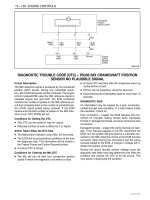
PROPORTIONING VALVE
The proportioning valve limits the outlet pressure to the
rear brakes on the non-ABS after a predetermined mas-
ter cylinder pressure has been reached. This is used
when less rear apply force is needed to obtain optimum
braking and is usually found on disc/drum brake configu-
rations. On ABS-equipped vehicles, refer to Section 4F,
Antilock Brake System.
FLUID LEVEL SENSOR
Fluid level sensor is attached at the brake fluid reservoir.
This sensor will activate the BRAKE light if a low fluid
level condition is detected. Once the fluid level is cor-
rected, the BRAKE light will go out.
MASTER CYLINDER 4B–3
DAEWOO M-150 BL2
DIAGNOSTIC INFORMATION AND PROCEDURES
CHECKING THE BRAKE FLUID
LEVEL
1. Check the fluid level.
2. If the fluid level is below MAX, refill the fluid to MAX.
D107A302
4B –4 MASTER CYLINDER
DAEWOO M-150 BL2
REPAIR INSTRUCTIONS
ON–VEHICLE SERVICE
MAB4B001
D107A514
MASTER CYLINDER ASSEMBLY
Removal Procedure
1. Remove the air filter assembly. Refer to Section 1B,
Engine Mechanical.
2. For vehicles with the non–ABS braking system, re-
move the proportioning valve. Refer to “Proportioning
Valve” in this section.
3. Remove the master cylinder.
D Disconnect the electrical connector.
D Loosen the brake pipe fittings.
D Plug the opening in the master cylinder to prevent
fluid loss or contamination.
Notice: Brake fluid may damage paintwork, if spillage
onto paintwork, wash with cold water immediately.
D Remove the nuts mounting the master cylinder (3).
D17A515A
Installation Procedure
Important: Use only Daewoo recommended brake
fluid.
1. Install the master cylinder assembly with the nuts.
Tighten
Tighten the attaching nuts to 16 NSm (12 lb-ft).
MASTER CYLINDER 4B–5
DAEWOO M-150 BL2
MAB4B002
2. Install the brake pipe fittings to the master cylinder.
Tighten
Tighten the fittings to 16 NSm (12 lb-ft).
3. Connect the electrical connector.
4. For vehicles with the non–ABS braking system, install
the proportioning valve. Refer to “Proportioning
Valve” in this section.
5. Install the air filter assembly. Refer to Section 1B, En-
gine Mechanical.
6. Bleed the brake system. Refer to Section 4A, Hy-
draulic Brakes.
D17A517A
BRAKE FLUID RESERVOIR
Removal Procedure
1. Remove the fluid level switch connector. Refer to
“Brake Fluid Level Switch” in this section.
2. Remove the reservoir.
D Drain the brake fluid.
D Remove the screw (1).
D Remove the fluid reservoir using a flathead screw-
driver (2).
Notice: Do not force one side strongly to prevent dam-
age of reservoir when removing the reservoir.
D17A518A
Installation Procedure
Important: Use only Daewoo recommended brake fluid.
1. Install the reservoir with the screw.
Tighten
Tighten the screw to 4 NSm (35 lb-ft).
2. Install the fluid level switch connector. Refer to “Brake
Fluid Level Switch” in this section.
3. Add brake fluid.
4. Bleed the brake system. Refer to Section 4A, Hy-
draulic Brakes.
MAB4B003
PROPORTIONING VALVE (FOR
VEHICLE WITH THE NON–ABS
BRAKING SYSTEM)
1. Remove the proportioning valve.
D Loosen the brake pipe fittings–to–proportioning
valve (1).
D Remove the proportioning valve (2).
D Plug the opening in the proportioning valve and
brake pipe fitting to prevent fluid loss or contamina-
tion.
4B –6 MASTER CYLINDER
DAEWOO M-150 BL2
Notice: Brake fluid may damage paintwork, if spillage
onto paintwork, wash with cold water immediately.
MAB4B004
Installation procedure
1. Install the proportioning valve (1).
Tighten
Tighten the proportioning valve to 22 NSm (16 lb-ft).
2. Install the brake pipe fitting (2).
Tighten
Tighten the brake pipe fitting–to–proportioning valve
to 16 NSm (12 lb-ft).
3. Bleed the brake system. Refer to Section 4A, Hy-
draulic Brakes.
D107A504
BRAKE FLUID LEVEL SWITCH
Removal procedure
1. Remove the vacuum hose from the power booster.
Refer to Section 4C, Power Booster.
2. Remove the brake fluid level switch.
D Remove the brake fluid level switch locking system
by the flathead screwdriver (1).
D107A505
D Disconnect the electrical connector (2).
MASTER CYLINDER 4B–7
DAEWOO M-150 BL2
D107A506
Installation procedure
1. Install the brake fluid level switch.
2. Connect the electrical connector.
3. Install the vacuum hose to the power booster. Refer
to Section 4C, Power Booster.
4B –8 MASTER CYLINDER
DAEWOO M-150 BL2
UNIT REPAIR
D24B001
MASTER CYLINDER
(ABS Type Master Cylinder is Shown,
Non–ABS Type Master Cylinder is Similar)
Disassembly Procedure
1. Remove the master cylinder. Refer to “Master Cylin-
der Assembly” in this section.
2. Remove the brake fluid reservoir. Refer to “Brake
Fluid Reservoir” in this section.
3. Remove the reservoir seals (1).
4. Remove the washer (2).
5. Remove the stop pin (3).
D24B002
6. Remove the boot (1).
7. Remove the retaining ring (2).
Notice: When removing the retaining ring, avoid dam-
aging the piston or the cylinder wall.
8. Remove the primary piston (3).
9. Carefully remove the secondary piston assembly
and the spring from the master cylinder bore (4).
D24B003
Assembly Procedure
1. Install the secondary piston assembly .
2. Install the stop pin.
3. Install the primary piston.
4. Install the retaining ring.
5. Install the boot.
6. Install the washer.
7. Install the reservoir seals.
8. Install the brake fluid reservoir. Refer to “Brake Fluid
Reservoir” in this section.
9. Install the master cylinder. Refer to “Master Cylinder
Assembly” in this section.
10. Raise and suitably support the vehicle.
11. Bleed the braking system. Refer to Section 4A, Hy-
draulic Brakes.
12. Lower the vehicle.
MASTER CYLINDER 4B–9
DAEWOO M-150 BL2
SPECIFICATIONS
GENERAL SPECIFICATIONS
Application Unit Description
Type – Tandem
Master Cylinder
Bore Diameter mm (in.) 20.64 (0.81)
Cut–In Pressure kPa (psi) 3,000(435.1)
Proportioning Valve
Pressure Ratio – 0.25 : 30
FASTENER TIGHTENING SPECIFICATIONS
Application NSm Lb-Ft Lb-In
Fluid Reservoir Screw 4 – 35
Master Cylinder Attaching Nuts 16 12 –
Brake Pipe Fittings to Master Cylinder 16 12 –
Brake Pipe Fittings to Proportioning Valve 16 12 –
Brake Pipe Fittings to Rear Wheel Cylinder 16 12 –
Brake Pipe Fittings to Front Caliper 16 12 –
Proportioning Valve 22 16 –