Daewoo matiz 2000 2013 manual sterring gear hệ thống lái không trợ lực trên xe matiz đời 2000 2013
Bạn đang xem bản rút gọn của tài liệu. Xem và tải ngay bản đầy đủ của tài liệu tại đây (592.83 KB, 18 trang )
DAEWOO M-150 BL2
SECTION 6D
MANUAL STEERING GEAR
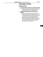
CAUTION: Disconnect the negative battery cable before removing or installing any electrical unit or when a
tool or equipment could easily come in contact with exposed electrical terminals. Disconnecting this cable
will help prevent personal injury and damage to the vehicle. The ignition must also be in B unless otherwise
noted.
TABLE OF CONTENTS
Description and Operation 6D-2. . . . . . . . . . . . . . . . . .
Manual Rack and Pinion 6D-2. . . . . . . . . . . . . . . . . . . .
Component Locator 6D-3. . . . . . . . . . . . . . . . . . . . . . . .
Manual Rack and Pinion Steering Gear 6D-3. . . . . . .
Diagnostic Information and Procedures 6D-4. . . . .
Manual Rack and Pinion Steering Gear 6D-4. . . . . . .
Straight-Ahead Check 6D-5. . . . . . . . . . . . . . . . . . . . . .
Steering Wheel Restoration 6D-6. . . . . . . . . . . . . . . . .
Check The Turning Resistance of the
Tie Rod End or Tie Rod 6D-6. . . . . . . . . . . . . . . . . . . .
Adjust the Free Load of the Steering Gear 6D-6. . . .
Repair Instructions 6D-7. . . . . . . . . . . . . . . . . . . . . . . . .
On-Vehicle Service 6D-7. . . . . . . . . . . . . . . . . . . . . . . . . .
Tie Rod End 6D-7. . . . . . . . . . . . . . . . . . . . . . . . . . . . . .
Rack and Pinion Boot 6D-8. . . . . . . . . . . . . . . . . . . . . .
Rack and Pinion Steering Gear Assembly 6D-9. . . .
Unit Repair 6D-11. . . . . . . . . . . . . . . . . . . . . . . . . . . . . . . .
Tie Rod End Boot 6D-11. . . . . . . . . . . . . . . . . . . . . . . .
Rack and Pinion 6D-11. . . . . . . . . . . . . . . . . . . . . . . . . .
Specifications 6D-17. . . . . . . . . . . . . . . . . . . . . . . . . . . .
General Specifications 6D-17. . . . . . . . . . . . . . . . . . . .
Fastener Tightening Specifications 6D-17. . . . . . . . . .
Special Tools and Equipment 6D-18. . . . . . . . . . . . . .
Special Tools Table 6D-18. . . . . . . . . . . . . . . . . . . . . . .
6D –2 MANUAL STEERING GEAR
DAEWOO M-150 BL2
DESCRIPTION AND OPERATION
MANUAL RACK AND PINION
The manual rack and pinion steering system consists of
two main components: the rack and the pinion. The mo-
tion of the pinion is transferred through the pinion teeth
that mesh with the teeth on the rack, which moves the
rack. The force is then transmitted through the arms on
the struts, which turn the wheels.
MANUAL STEERING GEAR 6D–3
DAEWOO M-150 BL2
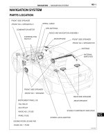
COMPONENT LOCATOR
MANUAL RACK AND PINION STEERING GEAR
(Left–Hand Drive Shown, Right–Hand Drive Similar)
D105B401
1. Manual Steering Gear
2. Steering Gear Bracket
3. Cotter Pin
4. Castellated Nut
5. Tie Rod End
6. Tie Rod End Lock Nut
7. Rack and Pinion Boot Clamp
8. Rack and Pinion Boot
9. Rack and Pinion Boot Wire Clamp
10. Tie Rod
11. Shock Damper Ring
12. Steering Rack Gear
13. Bulkhead Retainer
14. Bulkhead Bushing
15. Steering Gear Housing
16. Steering Gear Bracket Bushing
17. Packing
18. Dust Cover
19. Pinion Plug
20. Steering Pinion Gear
21. Roller Bearing
22. Rack Bearing
23. Adjuster Spring
24. Adjuster Plug
6D –4 MANUAL STEERING GEAR
DAEWOO M-150 BL2
DIAGNOSTIC INFORMATION AND PROCEDURES
MANUAL RACK AND PINION STEERING GEAR
Condition Probable Cause Correction
Excessive Play or
D Poor adjustment of steering gear. D Perform straight–ahead check.
Looseness in the
Steering System
D Improperly installed tie rods. D Tighten the tie rods.
D Improper and insufficient lubrication.
D Lubricate the rack and pinion
assembly.
Rattling Noise in the
Steering Gear
D Improperly installed steering gear mounting.
D Tighten the steering gear mounting
bolts.
D Improperly installed tie rods. D Tighten the tie rods.
MANUAL STEERING GEAR 6D–5
DAEWOO M-150 BL2
STRAIGHT-AHEAD CHECK
After all the necessary operations on the steering gear
are completed, check the exact straight-ahead position
of the steering in each case.
With the vehicle on the floor, place the steering wheel in
the straight-ahead position. Mark the centerline of both
tires on the floor. Turn the steering wheel all the way to
the right and mark the new centerline of both tires on the
floor.
Application Tire Specified Valve
145, 155 37.5 – 41.5_
Inside Angle
175 32.9 – 36.9_
145, 155 31.5 – 35.5_
Outside Angle
175
28.5 – 32.5_
D105B301
Front
Outside Angle
Inside Angle
Straight Ahead Check Table
Step Action Value(s) Yes No
1
Place the steering wheel in the straight-ahead posi-
tion.
Is the wheel in the correct position?
–
Go to Step 2
–
2
Is the steering wheel off center by more than 5 de-
grees? – Go to Step 4
Go to Step 5
3
The pinion is displaced on the rack. The steering
pinion position must be corrected.
Is the repair complete?
–
Go to Step 2
–
4
Remove steering wheel and center on the spindle
splines.
Is the repair complete?
–
Go to Step 2
–
5
Turn the steering wheel all the way to the right. Mea-
sure the inner and the outer angles of the tire cent-
erline compared to the straight-ahead centerline. Do
the angles match the value specified?
Refer to
“Straight–
Ahead Check”
in this section System OK
Go to Step 6
6
The rack assembly was not assembled correctly.
Repair as needed.
Is the repair complete?
–
Go to Step 5
–
6D –6 MANUAL STEERING GEAR
DAEWOO M-150 BL2
STEERING WHEEL RESTORATION
1. Turn the steering wheel fast to the right and left and
turn it slowly as the same way.
2. Check if the steering wheel restoration for the wheel
turning to right and the one to the left are same.
3. Turn the steering wheel to 90_ about 1–2 seconds
and loosen the steering wheel during the low speed
driving.
4. If the steering wheel restores above 70%, the steer-
ing wheel restoration is OK.
5. If the restoration is poor, check the tire pressure,
steering gear preload, and steering gear operation.
And repair the fault.
CHECK THE TURNING RESISTANCE
OF THE TIE ROD END OR TIE ROD
1. Turn the ball joint of the tie rod end or the tie rod about
10 times.
2. Use a spring balance to check the turning resistance
of each ball joint.
D105B302
Application Specified Value
Tie Rod End Ball Joint
0.49 – 3.43 NSm
(4.5 – 30 lb-in.)
Tie Rod Ball Joint
0.49 – 3.43 NSm
(4.5 – 30 lb-in.)
3. If the values exceed the specified values, replace the
tie rod end or the tie rod.
4. But, If the ball joint of the tie rod end or the tie rod falls
down of itself, replace it.
ADJUST THE FREE LOAD OF THE
STEERING GEAR
1. Place the steering wheel in the straight–ahead posi-
tion.
2. Raise and suitably support the vehicle.
3. Check the torque of the adjuster plug.
4 When the measured torque is below the specification
value or the measured torque is over the specification
value, adjust the tightening torque.
D Place the rack gear in the straight–ahead position.
D Tighten the adjust plug to 95 NSm (70 lb-ft).
D Turn the steering wheel all the way to the right and
the left about 5 times repeatedly.
D Place the rack gear in the straight–ahead position.
D Loosen the adjust plug.
D Tighten the adjust plug to 8 NSm (71 lb-in.).
D Set the torque in the 0.8–1.3 NSm (8–12 lb-in.) by
loosening the adjust plug to 0_ − 90_.
D105B303
MANUAL STEERING GEAR 6D–7
DAEWOO M-150 BL2
REPAIR INSTRUCTIONS
ON–VEHICLE SERVICE
D105B501
TIE ROD END
Tools Required
KM–507–B Ball Joint Remover
Removal Procedure
1. Remove the wheel. Refer to Section 2E, Tires and
wheels.
2. Disconnect the tie rod and from the steering knuckle.
D Remove the cotter pin (1).
D Remove the castellated nut (2).
D Use a ball joint remover KM–507–B, separate the
tie rod end (3).
D105B502
3. Remove the tie rod end.
D Mark the tie rod, tie rod end lock nut and tie rod end
(1).
D Loosen the tie rod end lock nut anticlockwise (2).
D Loosen the tie rod end (3).
D105B503
6D –8 MANUAL STEERING GEAR
DAEWOO M-150 BL2
D15B504B
Installation Procedure
1. Install the tie rod end.
2. Install the tie rod lock nut (1).
Tighten
Tighten the tie rod end lock nut to 35–55 NSm (25–41
lb-ft).
3. Connect the tie rod end to the knuckle.
4. Install the tie rod end castellated nut (2).
Tighten
Tighten the castellated nut to 30–55 NSm (21–41 lb-
ft).
5. Install the split pin.
6. Install the wheel. Refer to Section 2E, Tires and
Wheels.
7. Make the toe–in adjustment by turning the tie rod ad-
juster. Refer to Section 2B, Wheel Alignment.
D105B505
RACK AND PINON BOOT
Removal Procedure
1. Remove the tie rod end. Refer to “Tie Rod End” in this
section.
2. Remove the tie rod end lock nut.
D105B506
3. Remove the rack and pinion boot.
D Remove the boot clamp (1).
D Cut off the boot wire clamp (2).
MANUAL STEERING GEAR 6D–9
DAEWOO M-150 BL2
D105B507
D Coat the greases on the tie rod to ease removal
(3).
D Remove the boot (4).
D105B508
Installation Procedure
1. Install the rack and pinion boot with the clamp and the
wire clamp.
2. Install the tie rod end nut.
3. Install the tie rod end. Refer to “Tie Rod End” in this
section.
D105B509
D105B510
RACK AND PINION STEERING GEAR
ASSEMBLY
(Left–Hand Drive Shown, Right–Hand
Drive Similar)
Removal Procedure
1. Remove the intermediate shaft lower pinch bolt. Re-
fer to Section 6E, Steering Wheel and Column.
2. Remove the wheels. Refer to Section 2E, Tires and
Wheels.
3. Disconnect the tie rod end from the steering knuckle.
Refer to “Tie Rod End” in this section.
4. Remove the front exhaust pipe nuts. Refer to Section
1G, Engine Exhaust.
5. Remove the steering gear assembly from the vehicle.
D Remove the steering gear bracket bolts (1).
D Remove the steering gear bracket (2).
D Remove the steering gear assembly.
D Remove the packing (3).
6D –10 MANUAL STEERING GEAR
DAEWOO M-150 BL2
D15B511A
Installation Procedure
1. Install the mounting to the steering gear assembly.
2. Install the steering gear assembly.
3. Install the steering gear bracket with the bolts.
Tighten
Tighten the steering gear bracket bolts to 50–55 NSm
(36–41 lb-ft).
4. Install the front exhaust pipe nuts. Refer to Section
1G, Engine Exhaust.
5. Connect the tie rod end to the steering knuckle. Refer
to “Tie Rod End” in this section.
6. Install the wheels. Refer to Section 2E, Tires and
Wheels.
7. Install the intermediate shaft lower pinch bolt. Refer
to Section 6E, Steering Wheel and Column.
MANUAL STEERING GEAR 6D–11
DAEWOO M-150 BL2
UNIT REPAIR
D105B701
TIE ROD END BOOT
Disassembly Procedure
1. Remove the tie rod end. Refer to “Tie Rod End” in this
section.
2. Remove the tie rod end boot.
a. Tie rod end boot.
D105B702
Assembly procedure
Important : Coat the grease inside of the boot.
1. Install the boot to the tie rod end.
2. Install the tie rod end wire clamp.
3. Install the tie rod end. Refer to “Tie Rod End” in this
section.
D105B703
RACK AND PINION
(Left–Hand Drive Shown, Right–Hand
Drive Similar)
Disassembly Procedure
1. Remove the rack and pinion steering assembly from
the vehicle. Refer to “Rock and Pinion Assembly” in
this section.
2. Remove the rack and pinion boot.
D Remove the tie rod end. Refer to “Tie Rod End” in
this section (1).
D Remove the tie rod lock nut (2).
D Remove the rack and pinion boot clamp (3).
D Cut off the rack and pinion boot wire (4).
6D –12 MANUAL STEERING GEAR
DAEWOO M-150 BL2
D105B704
D Coat the greases on the tie rod (5).
D Remove the rack and pinion boot (6).
D105B705
3. Remove the tie rod
D Pull the rack gear perfectly from the steering gear
housing by turning the pinion gear (1).
D Disconnect the shock damper ring from the tie rod
ball joint (2).
D15B706A
D Vise the rack gear (3).
Important: Clothe the rack gear with a cloth before vis-
ing the rack gear.
Notice: Do not vise the rack gear over two teeth face.
D105B707
D Remove the tie rod (4).
D Remove the shock damper ring (5).
MANUAL STEERING GEAR 6D–13
DAEWOO M-150 BL2
D105B708
4. Remove the rack bearing.
D Remove the adjuster plug (1).
D Remove the adjuster spring (2).
D105B709
5. Remove the pinion and bearing assembly.
D Remove the dust cover (1).
D Remove the pinion plug (2).
Important: Do not reuse the removed pinion plug.
D105B710
D Remove the pinion and bearing assembly (3).
D105B711
6. Remove the rack gear toward the driver side of the
steering gear.
a. Rack gear.
Notice: Remove the rack gear toward the driver side of
the steering gear to prevent the bulk head in the steering
gear housing from damaging in installing and removing
the rack gear.
6D –14 MANUAL STEERING GEAR
DAEWOO M-150 BL2
D105B712
Inspection Procedure
1. Inspect the rack gear deformation and damage.
D Set the V–block on the plate (1).
D Set the rack gear on the V–block (2).
D Check the rack gear for deformation using a dial
gauge (3).
D Inspect the rack gear for wear and damage (4).
D105B713
2. Inspect the pinion and bearing assembly damage.
D Inspect the pinion gear for wear and damage (1).
D Inspect the bearing for loose and operation (2).
D105B714
3. Inspect the tie rod end boot and the rack and pinion
boot for damage.
D Inspect the tie rod end boot for crack and wear (1).
D Inspect the rack and pinion boot for crack and wear
(2).
D105B715
4. Inspect the steering gear housing for crack, deforma-
tion and wear.
a. Steering gear housing.
MANUAL STEERING GEAR 6D–15
DAEWOO M-150 BL2
D105B716
5. Inspect the tie rod end ball joint and tie rod ball joint
for damage.
D Inspect the tie rod end ball joint for operation (1).
D Inspect the tie rod ball joint for operation and tie rod
deformation (2).
6. After inspecting the parts, replace the defected parts.
D105B717
Assembly Procedure
Important: Coat the all turn, contact and rub surface
with grease.
1. Clean the all parts removed.
2. Install the rack gear.
D Coat the rack gear with grease (1).
D Insert the rack gear carefully (2).
D15B718A
3. Install the pinion and bearing assembly.
D Set the rack in balance (1).
D Coat the pinion and bearing assembly and steering
gear housing surface with grease.
D Install the pinion and bearing assembly (2).
D Coat the pinion plug with Loctitte.
D Install the pinion plug (3).
Tighten
Tighten the pinion plug to 40–60 NSm (30–44 lb-ft).
D Install the dust cover (4).
D105B719
4. Install the rack bearing.
D Coat the rack bearing with grease.
D Install the rack bearing (1).
D Install the adjuster spring (2).
D Tighten the adjuster plug softly (3).
6D –16 MANUAL STEERING GEAR
DAEWOO M-150 BL2
D15B720A
5. Install the tie rod.
D Install the shock damper ring to the rack gear (1).
D Vise the rack gear (2).
Important : Clothe the rack gear with a cloth before vis-
ing the rack gear.
Notice: Do not vise the rack gear above two teeth face.
D Coat the teeth face of the tie rod with Loctitte.
D Install the tie rod (3).
Tighten
Tighten the tie rod to 80–120 NSm (59–89 lb-ft).
D105B721
6. Install the shock damper ring to the tie rod ball joint.
a. Tie rod ball joint.
D Coat the tie rod ball joint with grease.
D105B722
7. Install the rack and pinion boot.
D Install the rack and pinion boot (1).
D Install the rack and pinion boot wire clamp (2).
D Install the rack and pinion boot clamp (3).
8. Install the tie rod end. Refer to “Tie Rod End” in this
sections.
9. Install the rack and pinion steering gear assembly to
the vehicle. Refer to “Rack and Pinion Steering
Gear Assembly” in this section.
10. Adjust the free load of the steering gear. Refer to
“Diagnosis” in this section.
MANUAL STEERING GEAR 6D–17
DAEWOO M-150 BL2
SPECIFICATIONS
GENERAL SPECIFICATIONS
Application Description
Type Rack and Pinion
Overall Gear Ratio 21 : 1
Inside 39.5_ ± 2_
145,155 Tire
Outside 33.5_ ± 2_
Steering Angle
Inside 34.9_ ± 2_
175 Tire
Outside 30.5_ ± 2_
Rack Gear POLYUREAS
Lubricant
Ball Joint SYNTHETICS OILS & LI SOAPS
Locktite Type DAC SPEC ADHESIVE SEALANT #520414
FASTENER TIGHTENING SPECIFICATIONS
Application NSm Lb-Ft Lb-In
Tie Rod End Castellated Nut 30 – 55 21 – 41 –
Tie Rod End Lock Nut 35 – 55 25 – 41 –
Steering Gear Bracket Bolts 50 – 55 36 – 41 –
Tie Rod–to–Rack Gear 80 – 120 59 – 89 –
Pinion Plug 40 – 60 30 – 44 –
Pinion Preload Refer to “Diagnosis” in this section.
6D –18 MANUAL STEERING GEAR
DAEWOO M-150 BL2
SPECIAL TOOLS AND EQUIPMENT
SPECIAL TOOLS TABLE
D105B101
KM–507–B
Ball Joint Remover