Daewoo matiz 2000 2013 power booster hệ thống trợ lực phanh trên xe matiz đời 2000 2013
Bạn đang xem bản rút gọn của tài liệu. Xem và tải ngay bản đầy đủ của tài liệu tại đây (226.35 KB, 8 trang )
DAEWOO M-150 BL2
SECTION 4C
POWER BOOSTER
TABLE OF CONTENTS
Description and Operation 4C-2. . . . . . . . . . . . . . . . . .
Power Booster 4C-2. . . . . . . . . . . . . . . . . . . . . . . . . . . .
Diagnostic Information and Procedures 4C-3. . . . .
Power Booster Functional Check 4C-3. . . . . . . . . . . .
Check Valve Functional Check 4C-3. . . . . . . . . . . . . .
Repair Instructions 4C-4. . . . . . . . . . . . . . . . . . . . . . . . .
On-Vehicle Service 4C-4. . . . . . . . . . . . . . . . . . . . . . . . . .
Vacuum Hose and Check Valve 4C-4. . . . . . . . . . . . .
Power Booster Assembly 4C-5. . . . . . . . . . . . . . . . . . .
Specifications 4C-8. . . . . . . . . . . . . . . . . . . . . . . . . . . . .
General Specifications 4C-8. . . . . . . . . . . . . . . . . . . . .
Fastener Tightening Specifications 4C-8. . . . . . . . . . .
4C –2 POWER BOOSTER
DAEWOO M-150 BL2
DESCRIPTION AND OPERATION
POWER BOOSTER
This booster is a single diaphragm, vacuum-suspended
unit. In a normal operating mode, with the service brakes
in the release position, a vacuum-suspended booster
operates with a vacuum on both sides of its diaphragm.
When the brakes are applied, air at atmospheric pres-
sure is admitted to one side of the diaphragm to pro-
vide the power assist. When the brakes are released, at-
mospheric air is shut off from that side of the diaphragm.
The air is then drawn from the booster through the vacu-
um check valve by the vacuum source.
Important: If any hydraulic component is removed or
disconnected, it may be necessary to bleed all or part of
the brake system.
POWER BOOSTER 4C–3
DAEWOO M-150 BL2
DIAGNOSTIC INFORMATION AND PROCEDURES
POWER BOOSTER FUNCTIONAL
CHECK
1. With the engine stopped, eliminate the vacuum in the
booster by pumping the brake pedal several times.
2. Push the pedal down and hold it in this position.
3. Start the engine.
4. The booster is OK if the pedal drops further because
of extra force produced.
If the brake pedal does not drop, the vacuum system
(vacuum hoses, check valve, etc.) is probably defective
and should be checked.
If no defect is revealed by checking the vacuum system,
the defect is in the booster itself.
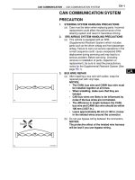
CHECK VALVE FUNCTIONAL CHECK
1. Remove the vacuum hose.
2. Suck the vacuum hose to power booster. And also,
suck the vacuum hose to engine.
3. If the air pass through the check valve or not, replace
the check valve. And if the vacuum hose to engine is
only sucked, the check valve OK.
D17A301B
4C –4 POWER BOOSTER
DAEWOO M-150 BL2
REPAIR INSTRUCTIONS
ON–VEHICLE SERVICE
D107A501
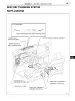
VACUUM HOSE AND CHECK VALVE
Removal Procedure
1. Remove the vacuum hose.
D Disconnect the vacuum hose from the intake man-
ifold (1).
D17A502A
D Disconnect the vacuum hose from the power
booster (2).
D107A503
Installation Procedure
1. Connect the vacuum hose to the power booster.
2. Connect the vacuum hose to the intake manifold.
POWER BOOSTER 4C–5
DAEWOO M-150 BL2
D107A519
POWER BOOSTER ASSEMBLY
(LEFT–HAND DRIVE)
Removal Procedure
1. Remove the master cylinder assembly. Refer to Sec-
tion 4B, Master Cylinder.
2. Disconnect the vacuum hose from the power booster.
3. Remove the power booster.
D Straighten the cotter pin and remove it (1).
D Remove the clevis pin (2).
D107A520
D Remove the nuts (3).
D107A521
D Remove the power booster (4).
D17A522A
Installation Procedure
1. Install the power booster with the new cotter pin, cle-
vis pin and nuts.
Tighten
Tighten the nuts to 16 NSm (12 lb-ft).
Important: Make sure the distance from the booster
to the center of the clevis bore should be 100mm
(3.94 in.).
2. Install the master cylinder assembly. Refer to Section
4B, Master Cylinder.
3. Connect the vacuum hose to the power booster.
4. Bleed the brake system. Refer to Section 4A, Hy-
draulic Brakes.
4C –6 POWER BOOSTER
DAEWOO M-150 BL2
D24C001
POWER BOOSTER ASSEMBLY
(RIGHT–HAND DRIVE)
Removal Procedure
1. Remove the master cylinder assembly. Refer to Sec-
tion 4B, Master Cylinder.
2. Disconnect the vacuum hose from the power booster.
3. Remove the instrument panel assembly. Refer to
Section 9E, Instrument/Driver Information.
4. Remove the evaporator unit mounting screws and
take off the evaporator unit a little. Refer to Section
7B, Manual Control Heating, Ventilation, and Air Con-
ditioning System.
5. Remove the power booster.
D Straighten the cotter pin and remove it (1).
D Remove the clevis pin (2).
D24C002
D Remove the nuts (3).
D107A521
D Remove the power booster (4).
POWER BOOSTER 4C–7
DAEWOO M-150 BL2
D24C003
Installation Procedure
1. Install the power booster with the new cotter pin, cle-
vis pin and nuts.
Tighten
Tighten the nuts to 16 NSm (12 lb-ft).
Important: Make sure the distance from the booster
to the center of the clevis bore should be 100mm
(3.94 in.).
2. Install the evaporator unit with the screws. Refer to
Section 7B, Manual Control Heating, Ventilation, and
Air Conditioning System.
3. Install the instrument panel assembly. Refer to Sec-
tion 9E, Instrument/Driver Information.
4. Connect the vacuum hose to the power booster.
5. Install the master cylinder assembly. Refer to Section
4B, Master Cylinder.
4C –8 POWER BOOSTER
DAEWOO M-150 BL2
SPECIFICATIONS
GENERAL SPECIFICATIONS
Application Unit Description
Type – Vacuum–Suspended
Diameter mm (inch) 177.8 (7)
Power Booster
Servo Force Ratio – 3.7 : 1
Distance from the booster to
the center of the clevis bore
mm (inch) 96(3.78)
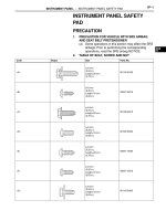
FASTENER TIGHTENING SPECIFICATIONS
Application NSm Lb-Ft Lb-In
Booster–to-Dash Panel Nuts 16 12 –
Master Cylinder Attaching Nuts 16 12 –