ĐỘNG học và NHIỆT ĐỘNG học TRONG CÔNG NGHỆ lọc dầu
Bạn đang xem bản rút gọn của tài liệu. Xem và tải ngay bản đầy đủ của tài liệu tại đây (5.64 MB, 181 trang )
10/1/2010
1
CHBI 502
REACTION ENGINEERING
CHBI 502
• HWs will be distributed after the chapters are covered, deadlines will be
posted
–
NO late submission
• MT dates will be determined (mid of the semester)
• Final exam date will be determined by the registrar’s office
• You can contact me anytime through e-mail (okeskin@ )
• You are wellcome during office hours, you need to ask me if I will be at the
office other than these hours.
•No cheating (HWs, projects, exams)
10/1/2010
2
POLICY ON COLLABORATION AND ORIGINALITY
Academic dishonesty in the form of cheating, plagiarism, or collusion are serious offenses and
are not tolerated at Koç University. University Academic Regulations and the Regulations for
Student Disciplinary Matters clearly define the policy and the disciplinary action to be taken in
case of academic dishonesty.
Failure in academic integrity may lead to suspension and expulsion from the University.
Cheating includes, but is not limited to, copying from a classmate or providing answers or
information, either written or oral, to others. Plagiarism is borrowing or using someone else’s
writing or ideas without giving written acknowledgment to the author. This includes copying
from a fellow student’s paper or from a text (whether printed or electronic) without properly
citing the source. Collusion is getting unauthorized help from another person or having
someone else write a paper or assignment. You can discuss the lecture and reading material,
and the general nat re of the home ork problems ith an one Also o ma per se all
and
the
general
nat
u
re
of
the
home
w
ork
problems
, w
ith
an
y
one
.
Also
, y
o
u
ma
y
per
u
se
all
previous ChBI 502 material available anywhere, such as on the web, and in the library
accumulated over the years. However, your final solutions should be your own original work.
Jointly prepared solutions, and solutions closely resembling those available, are unacceptable.
• Textbook Elements of Chemical Reaction Engineering
(4th ed.), H.S. Fogler Prentice Hall,
Upper Saddle River, NJ (2005).
10/1/2010
3
• Course Outline, Tentative schedule
•
• Review: Chemical Kinetics and Ch1-6, Two-three weeks
• Chapter 1: Mole Balances
•
Chapter 2:
Conversion and Reactor Sizing
•
Chapter
2:
Conversion
and
Reactor
Sizing
• Chapter 3: Rate Law and Stoichiometry
• Chapter 4: Isothermal Reactor Design
• Chapter 5: Collection and Analysis of Rate Data
• Chapter 6: Multiple Reactions
• Chapter 7: Reaction Mechanisms, Pathways, Bioreactions and Bioreactors , Two weeks
• Chapter 8: Steady-State Nonisothermal Reactor Design, Two weeks
• Chapter 9: Unsteady-state Nonisothermal Reactor Design, One week
• Chapter 10: Catalysis and Catalytic Reactors, Two weeks
•
Chapter 11:
External Diffusion Effects on Heterogeneous Reactions
One Week
•
Chapter
11:
External
Diffusion
Effects
on
Heterogeneous
Reactions
,
One
Week
• Chapter 12: Diffusion and Reaction in Porous Catalysts, Two Weeks
• Student presentations on projects, One week
Elements of Chemical Rxn EnginneringElements of Chemical Rxn Enginnering
Chemical kinetics is the study of chemical rxn rates and reaction Chemical kinetics is the study of chemical rxn rates and reaction
mechanisms.mechanisms.
Chemical reaction engineering (CRE) combines the study of chemical Chemical reaction engineering (CRE) combines the study of chemical
kinetics with the reactors in which the reactions occur.kinetics with the reactors in which the reactions occur.
Objective of the course: Objective of the course: Learn how to design equipment for Learn how to design equipment for
carrying out desirable chemical reactions carrying out desirable chemical reactions
(what size and what type of equipment)(what size and what type of equipment)
Chemical Kinetics & Reactor DesignChemical Kinetics & Reactor Design
The reaction system thet operates in the safest and most efficient manner The reaction system thet operates in the safest and most efficient manner
can be the key to the success of the plant.can be the key to the success of the plant.
ca be t e ey to t e success o t e p a tca be t e ey to t e success o t e p a t
Modelling of;Modelling of;
Chemical plantChemical plant
PharmacokineticsPharmacokinetics
MicroelectronicsMicroelectronics
Digestive system of an animalDigestive system of an animal
10/1/2010
4
Chapter1 MOLE BALANCESChapter1 MOLE BALANCES
1. Chemical Identity
A chemical species is said to have reacted when it has lost its
h i l id tit Th id tit f h i l i i d t i d
c
h
em
i
ca
l
id
en
tit
y.
Th
e
id
en
tit
y o
f
a c
h
em
i
ca
l
spec
i
es
i
s
d
e
t
erm
i
n
d
e
by the kind, number, and configuration of that species’ atoms.
Three ways a chemical species can lose its chemical identity:
1. Decomposition CH
3
CH
3
→ H
2
+ H
2
C = CH
2
2C bi ti
N
O
2NO
2
.
C
om
bi
na
ti
on
N
2
+
O
2
→
2NO
3. Isomerization C
2
H
5
CH = CH
2
→ CH
2
= C(CH
3
)
2
2. Reaction Rate:
The reaction rate is the rate at which a species looses its chemical
identity per unit volume
The rate of a reaction can be expressed as
identity
per
unit
volume
.
The
rate
of
a
reaction
can
be
expressed
as
the rate of disappearance of a reactant or as the rate of appearance
of a product. Consider species A:
A → B
r
A
= the rate of formation of s
p
ecies A
p
er unit volume
A
pp
-r
A
= the rate of disappearance of species A per unit volume
r
B
= the rate of formation of species B per unit volume
10/1/2010
5
Example: A → B
If B is being created 0.2 moles per decimeter cubed per second, ie,
r
B
= 0.2 mole/dm
3
s
Then A is disappearing at the same rate:
-r
A
= 0.2 mole/dm
3
s
For catalytic reaction, we refer to –r
A
’, which is the rate of disappearance of
species A on a per mass of catalyst basis.
NOTE: dC
A
/dt is not the rate of reaction (This is only true for a batch system, we will see)
If continuous → dC
A
/
dt = 0
A
The rate law does not depend on reactor type!
-r
A
is the # of moles of A reacting (disappearing) per unit time per unit volume
(mol/dm
3
s)
In a reactor, two extreme conditions are considered:
1. No mixing of streams
2. Complete mixing (desirable)
Classification of reactions
• Ideal mixing (no axial mixing, complete radial mixing)
• Steady-state : conditions donot change with time at any point (PFR)
• Complete mixing
•
non-steady-state: Uniform composition and temperture at any given instant,
change with time (t)
change
with
time
(t)
F
A0
F
A
Batch CSTR)
Stirrer, rpm and design are important
10/1/2010
6
Thus,
• Batch or continuous
• Tank or tubula
r
• Homogeneous or heterogeneous
Consider species j:
r
j
is the rate of formation of species j per unit volume [e.g. mol/dm
3
s]
r
j
is a function of concentration, temperature, pressure, and the type of
catalyst (if any)
r
j
is independent of the type of reaction system (batch, plug flow, etc.)
r
j
is an algebraic equation, not a differential equation.
We use an algebraic equation to relate the rate of reaction, -r
A
, to the
concentration of reacting species and to the temperature at which the reaction
occurs [e.g. –r
A
= k(T) C
A
2
]
For example, the algebraic form of the rate law for –r
A
for A (products) may be;
A
A
Ckr ⋅
=
−
a linear function of concentrations:
or can be determined by experiments:
A
A
A
Ck
Ck
r
⋅+
⋅
=−
2
1
1
2
AA
Ckr ⋅=−
or, it may be some other algebraic function of conc’n as:
10/1/2010
7
3. General Mole Balance Equation:
IN – OUT + GENERATION = ACCUMULATION
]
/
[
0
timemoles
d
dN
dV
r
F
F
V
A
A
A
A
∫
=
⋅+−
N
A
: # of moles
of species A in
]
[
0
0
d
t
A
A
A
∫
of
species
A
in
the system at
time t.
G
A
= r
A
V (if all system variables (T, C
A
, etc.) are spatially uniform
throughout system volume)
[]
volume
volumetime
moles
time
moles
VrG
AA
⋅
⎥
⎦
⎤
⎢
⎣
⎡
⋅
=
⎥
⎦
⎤
⎢
⎣
⎡
⋅
=
If the rate of formation of A varies with position:
∆V
1
∆V
2
r
1A
1A
r
2A
subvolumesMforVrGG
subvolumesallforetcVrG
m
i
iiA
m
i
iAA
AA
∆
⋅
=∆
=
∆
⋅=
∆
∑
∑
1
1
111
.
Basic equation for any species A
entering, leaving, reacting
dt
dN
dVrFF
dVrG
A
V
AAA
AA
i
i
=⋅+
−
⋅=
∫
∫
∑
∑
==
0
0
1
1
10/1/2010
8
Mole Balance on Different Reactor TypesMole Balance on Different Reactor Types
Batch Reactor is used for small-scale operations, for testing new
processes, for the manufacture of expensive products, and for the
processes that are not easy to convert to continuous.
processes
that
are
not
easy
to
convert
to
continuous.
high conversion rates (time spend is longer)
high labor cost and & variability of products from batch-to-batch
=
=
V
d
N
FF
A
AA
00
0
If perfect mixing
∫
⋅=
⋅
=
dVr
dt
dN
V
r
dt
j
j
A
A
If
perfect
mixing
(no volume change throughout
volume)
The # of moles changing (in A → B) is as follows:
N
A0
N
A1
N
A
N
B
N
B1
t
1
t
N
A1
tt
1
⋅=
A
A
Vr
dt
dN
What time is the necessary to produce N
A1
starting from N
A0
?
∫∫∫
⋅
=⇒
⋅
=
⋅
=
1
0
1
0
1
1
0
A
A
A
A
N
N
A
A
N
N
A
A
t
A
A
Vr
dN
t
Vr
dN
dt
Vr
dN
dt
dt
10/1/2010
9
Continuous Flow Reactors (CFR) operate at steady state.
Continuous Stirred Tank Reactor (CSTR)
Plug Flow Reactor (PFR)
Packed Bed Reactor (PBR)
CSTR
F
A0
F
A
usually used for liquid-phase rxns
usually operated at steady state
usually assumed to be perfectly mixed
T ≠ f(t,V)
General Mole Balance on System Volume V
IN – OUT + GENERATION = ACCUMULATION
∫
=⋅+−
V
A
AAA
dt
dN
dVrFF
0
0
V
F
A0
F
A
Assumptions
AAA
AA
A
VrFF
VrdVr
dt
dN
=⋅+−
⋅=⋅
=
∫
0
0
0
Steady State
Well mixed
A
AA
A
AA
r
vCvC
V
r
FF
V
−
⋅−⋅
=
−
−
=
00
0
Design eq’n for CSTR
vCF
AA
⋅
=
00
Molar flow rate
concentration
10/1/2010
10
Tubular Reactors consists of a cylindirical pipe and is operated at
steady state. Mostly used for gas phase rxns.
PFR Derivation: uniform velocity in turbulent flow (no radial variation in
velocity, concentration, temperature, reaction rate)
∫
=⋅+−
V
A
AAA
dt
dN
dVrFF
0
0
IN – OUT + GENERATION = ACCUMULATION
Reactants Products
10/1/2010
11
∆
⋅
=
⋅
=
∆
∆
∫
V
r
dV
r
G
V
A
A
A
∆G
A
F
A
F
j
F
A0
VV + ∆V
0=∆⋅+−
∆
∆
∆+
∫
VrFF
V
r
dV
r
G
A
VV
A
V
A
A
A
A
Divide by ∆V and rearrange:
A
V
A
VV
A
r
V
FF
=
⎥
⎥
⎦
⎤
⎢
⎢
⎣
⎡
∆
−
∆+
Taking the limit as ∆V→0:
∫
=
=
A
A
F
F
A
A
A
A
r
dF
V
r
dV
dF
0
Packed Bed Reactors (PBR) are not homogenous, the fluid-solid
heterogenous rxn take place on the surface of the catalyst. Rate (r’) is
dependent on the mass of catalyst (W).
-rA’ = mol A reacted / (s) (g catalyst)
General Balance on W
General
Balance
on
W
∫
=⋅+−
V
A
AAA
dt
dN
dWrFF
0
0
'
IN – OUT + GENERATION = ACCUMULATION
∆
W
∆
W
W+∆WW
F
A
(W+∆W)F
A
(W)
10/1/2010
12
∫
=
⋅
+
−
V
A
A
A
A
dN
d
V
r
F
F
0
'
0=
d
t
dN
A
Steady State
∫
A
A
A
dt
0
0
Differentiate with respect to W and rearrange
'
A
A
r
dW
dF
=
When pressure drop through the reactor and catalyst decay are
When
pressure
drop
through
the
reactor
and
catalyst
decay
are
neglected, the integral eg’n can be used to find W:
∫∫
−
==
0
0
''
A
A
A
A
F
F
A
A
F
F
A
A
r
dF
r
dF
W
Batch Reactor Times
A → B
Calculate the time to reduce the number of moles by a factor of 10 (N
A
=
N
A0
/10) in a batch reactor for the above reaction with
-
r
A
’
=
kC
A
when k
=
0.046 min
-1
r
A
k
C
A
when
k
0.046
min
A
A
law
Rate
dt
dN
Vr
onAccumulatiGenerationOutIn
balanceMol
=⋅+−
=+−
:
00
:
A
A
AA
A
AAAA
Nk
dt
dN
NkVr
V
N
kCkrCkr
law
Rate
⋅−=⇒⋅−=⋅
⎟
⎠
⎞
⎜
⎝
⎛
⋅−=⋅−=⇒⋅=−
:
10/1/2010
13
:
00
⋅−
−=
⋅
=
∫∫
Vr
dN
Vr
dN
t
Solve
N
N
A
A
N
N
A
A
A
A
A
A
ln
1
0
0
⋅=
⋅
=
⋅=⋅⋅=⋅⋅=⋅−
∫
N
N
kNk
dN
t
NkV
V
N
kVCkVr
A
A
N
N
A
A
A
A
AA
A
A
)10ln(
mi
n
046.0
1
10
0
⋅=⇒= t
N
N
A
A
Therefore, t = 50 minutes
Summary of Chapter 1
• Define the rate of chemical reaction.
• Apply the mole balance equations to a batch reactor, CSTR, PFR,
and PBR.
and PBR.
• Batch reactor: no in-out streams, no spatial variations in
conc’n
• CSTR: no spatial variations in the tank, steady state
•
PFR:
spatial variations along the reactor steady state
PFR:
spatial variations along the reactor
,
steady state
• PBR: spatial variations along the reactor, steady state
Basic equation for any species A
entering, leaving, reacting
dt
dN
dVrFF
A
V
AAA
=⋅+−
∫
0
0
10/1/2010
14
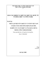
Reactor Differential Algebraic Integral
Batch
CSTR
PFR
PBR
general reaction, A->B
10/1/2010
15
10/1/2010
16
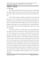
Compartments for perfusion
Stomach
V
G
= 2.4 l
Gastrointestinal
V
G
= 2.4 l
t
G
= 2.67 min
Liver
Alcohol
Perfusion interactions between
compartments are shown by arrows.
V
L
= 2.4 l
t
L
= 2.4 min
Central
V
C
= 15.3 l
t
C
= 0.9 min
V
G
, V
L
, V
C
, and V
M
are -tissue water
volumes for the gastrointestinal,
liver, central and muscle
compartments, respectively.
V
S
is the stomach contents volume.
Muscle & Fat
V
M
= 22.0 l
t
M
= 27 min
10/1/2010
17
Chemical Reaction Engineering
Chemical reaction engineering is at the heart of virtually
every chemical process. It separates the chemical
engineer from other engineers.
Industries that Draw Heavily on Chemical Reaction
Engineering (CRE) are:
CPI (Chemical Process Industries)
Dow, DuPont, Amoco, Chevron
Pharmaceutical – Antivenom, Drug Delivery
Medicine –Pharmacokinetics, Drinking and
Driving
Microelectronics – CVD
1
• Objectives:
CONVERSION AND REACTOR SIZINGCONVERSION AND REACTOR SIZING
• Define conversion and space time.
• Write the mole balances in terms of conversion for a
batch reactor, CSTR, PFR, and PBR.
• Size reactors either alone or in series once given the
molar flow rate of A, and the rate of reaction, -r
A
, as
a function of conversion,
X
.
• Conversion: Choose one of the reactants as the basis
of calculation and relate the other species involved in
of calculation and relate the other species involved in
the rxn to this basis.
• Space time: the time necessary to process one
reactor volume of fluid based on entrance conditions
(holding time or mean residence time)
2
CONVERSION AND REACTOR SIZINGCONVERSION AND REACTOR SIZING
1. Conversion
Consider the general equation
dD
C
bB
A
dD
c
C
bB
a
A
+
→
+
We will choose A as our basis of calculation.
D
a
d
C
a
c
B
a
b
A +→+
The basis of calculation is most always the limiting reactant. The
conversion of species A in a reaction is equal to the number of moles of A
reacted per mole of A fed.
00
)()(
A
A
A
A
FF
X
NN
X
−
=
−
=
Batch Flow
00 AA
F
X
N
X
=
=
X = Moles of A reacted
Moles of A fed
For irreversible reactions, the maximum value of conversion, X, is
that for complete conversion, i.e. X = 1.0.
For reversible reactions
, the maximum value of conversion, X, is the
equilibrium conversion, i.e. X = X
e
.
3
Batch Reactor Design Equations:Batch Reactor Design Equations:
⎤
⎡
⎤
⎡
⎥
⎤
⎢
⎡
reacted
A
of
Moles
A
of
Moles
AofMoles
2.2. Design EquationsDesign Equations
⎥
⎦
⎤
⎢
⎣
⎡
⋅
⎥
⎦
⎤
⎢
⎣
⎡
=
⎥
⎥
⎦
⎢
⎢
⎣
fedAofMoles
reacted
A
of
Moles
fed
A
of
Moles
consumed
reacted
)(
[]
0A
N=
[]
X⋅
[1]
Now the # of moles of A that remain in the reactor after a time t, N
A
can be
expressed in terms of N
A0
and X;
expressed
in
terms
of
N
A0
and
X;
[][ ][ ]
)1(
0
00
XNN
XNNN
AA
AAA
−⋅=
⋅
−=
[2]
Vr
dt
dN
mixingprefectVr
dt
dN
A
A
A
A
⋅−=−
⋅= )(
[3]
For batch reactors, we are interested in determining how long to leave the
reactants in the reactor to achieve a certain conversion X.
dX
dt
dX
N
dt
dN
A
A
⋅−=
0
0
(Since N
A0
is constant) [4]
Vr
dt
dX
N
Vr
dt
dX
N
AA
AA
⋅−=⋅
⋅=⋅−
0
0
Batch reactor design eq’n
(in differential form)
[5]
4
For a constant volume batch reactor: (V = V
0
)
==⋅
AAA
dt
dC
dt
VNd
dt
dN
V
0
0
)/(1
From [3]
∫
⋅=
⋅−
⋅=
=
X
A
A
A
A
A
V
r
dX
Nt
Vr
dX
Ndt
r
dt
d
C
0
0
From [5]
Constant volume batch
reactor
Batch time, t, required
to achieve a
∫
⋅
−
A
V
r
0
conversion X.
X
t
As t X
Flow Reactor Design Equations:Flow Reactor Design Equations:
reacted
A
of
moles
fed
A
of
moles
For continuous-flow systems, time usually increases with increasing reactor
volume.
AAA
A
FXFF
fedAofmoles
reacted
A
of
moles
time
fed
A
of
moles
X
F
=⋅−
⋅
=⋅
00
0
inlet molar
flow rate
Molar flow rate at which A is
consumed within the system
Outlet flow rate
000
0
)1(
vCF
XFF
AA
AA
⋅=
−
⋅=
moles /volume
volume / time (volumetric flow rate, dm
3
/s)
5
For liquid systems, C
A0
is usually given in terms of molarity (mol/dm3)
For gas systems, C
A0
can be calculated using gas laws.
P
P
Partial pressure
0
00
0
0
0
TR
P
y
TR
P
C
AA
A
⋅
⋅
=
⋅
=
P
y
⋅
Entering molar flow rate is
y
A0
= entering mole fraction of A
P
t i ttl (kP)
0
00
0000
TR
P
y
v
C
v
F
A
AA
⋅
⋅=⋅=
P
0
= en
t
er
i
ng
t
o
t
a
l
pressure
(kP
a
)
C
A0
= entering conc’n (mol/dm
3
)
R = 8.314 kPa dm
3
/ mol K
T = T(K)
CSTR (Design Equation)CSTR (Design Equation)
D
a
d
C
a
c
B
a
b
A +→+
For a rxn:
F
F
A
AA
r
F
F
V
−
−
=
0
Substitute for F
A
AAA
AAA
XFFF
V
XFFF
)(
000
00
⋅−−
=
⋅−=
exitA
A
A
r
XF
V
r
)(
0
−
⋅
=
−
6
PFR (Design Equation)PFR (Design Equation)
r
dV
dF
A
A
−=−
dXFdF
X
F
F
F
AA
AAA
⋅−=
⋅
−
=
0
00
Substitute back:
AA
A
r
dV
dX
F
dV
dF
−=⋅=−
0
Seperate the variables V = 0 when X = 0
∫
−
⋅=
X
A
A
r
dX
FV
0
0
Applications of Design Equations for Applications of Design Equations for
Continuous Flow ReactorsContinuous Flow Reactors
3.3. Reactor SizingReactor Sizing
Given –r
A
as a function of conversion, -r
A
= f(X), one can size any type of
reactor. We do this by constructing a Levenspiel Plot. Here we plot either
F
A0
/ -r
A
or 1 / -r
A
as a function of X. For F
A0
/ -r
A
vs. X, the volume of a
CSTR and the volume of a PFR can be represented as the shaded areas
in the Levelspiel Plots shown below:
Levenspiel PlotsLevenspiel Plots
7
A particularly simple functional dependence is the first order dependence:
)1(
0
XCkCkr
AAA
−
⋅
⋅
=
⋅
=
−
Specific rxn rate
(
function of T
)
initial conc’n
()
For this first order rxn, a plot of 1/-r
A
as a function of X yields :
⎟
⎠
⎞
⎜
⎝
⎛
−
⋅
⋅
=−
XCkr
AA
1
111
0
-1/r
A
X
Example:Example: Let’s consider the isothermal gas-phase isomerization:
A → B
X-r
A
(mol/m
3
s)
0
045
0
0
.
45
0.1 0.37
0.2 0.30
0.4 0.195
0.6
0.7
0.113
0.079
08
005
0
.
8
0
.
05
[T = 500 K]
[P = 830 kPa = 8.2 atm]
initial charge was pure A
8
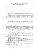
Example:Example: Let’s consider the isothermal gas-phase isomerization:
A → B
X-r
A
(mol/m
3
s) 1 / -r
A
0
045
222
0
0
.
45
2
.
22
0.1 0.37 2.70
0.2 0.30 3.33
0.4 0.195 5.13
0.6
0.7
0.113
0.079
8.85
12.7
08
005
20 0
0
.
8
0
.
05
20
.
0
[T = 500 K]
[P = 830 kPa = 8.2 atm]
initial charge was pure A
-1/r
A
Draw Draw 1/r1/r
AA
vs X:vs X:
We can use this figure to size flow reactors for
different entering molar flow rates.
Keep in mind :
1. if a rxn is carried out isothermall
y,
the rate is
X
y,
usually greatest at the start of the rxn, when
the conc’n of reactant is greatest. (when x ≈
0 → -1/r
A
is small)
2. As x → 1, –r
A
→ 0 thus 1/-r
A
→ ∞ & V → ∞
→ An infinite reactor volume is needed to reach complete conversion.
For reversible reactions (A ↔ B), the max X is the equilibrium conversion
X
e
. At equilibrium, r
A
≈ 0.
As X → X
e
, –r
A
→ 0 thus 1/-r
A
→ ∞ & V → ∞
→ An infinite reactor volume is needed to obtain X
e
.