essential lightwave 3d 8
Bạn đang xem bản rút gọn của tài liệu. Xem và tải ngay bản đầy đủ của tài liệu tại đây (28.73 MB, 629 trang )
Essential LightWave
â
3D [8]
The Fastest and Easiest
Way to Master LightWave
Timothy Albee and Steve Warner
with R obin Wood
Wordware Publishing , Inc.
Library of Congress Cataloging-in-Publication Data
Albee, Timothy.
Essential lightwave 3D8/byTimothy Albee and Steve Warner with Robin Wood.
p. cm.
Includes index.
ISBN 1-55622-082-0 (pbk., companion CD-ROM)
1. Computer animation. 2. Computer graphics. 3. LightWave 3D.
I. Warner, Steve, 1970- II. Wood, Robin, 1953- III. Title.
TR897.7.A4215 2005
006.6'96 dc22 2004029130
CIP
© 2005, Wordware Publishing, Inc.
All Rights Reserved
2320 Los Rios Boulevard
Plano, Texas 75074
No part of this book may be reproduced in any form or by
any means without permission in writing from
Wordware Publishing, Inc.
Printed in the United States of America
ISBN 1-55622-082-0
10987654321
0412
LightWave
®
, LightWave 3D
®
, HyperVoxels™, Particle FX™, and Video Toaster
®
are trademarks or registered trademarks of
NewTek, Inc. in the United States and other countries.
All brand names and product names mentioned in this book are trademarks or service marks of their respective companies.
Any omission or misuse (of any kind) of service marks or trademarks should not be regarded as intent to infringe on the prop
-
erty of others. The publisher recognizes and respects all marks used by companies, manufacturers, and developers as a
means to distinguish their products.
This book is sold as is, without warranty of any kind, either express or implied, respecting the contents of this book and any
disks or programs that may accompany it, including but not limited to implied warranties for the book’s quality, performance,
merchantability, or fitness for any particular purpose. Neither Wordware Publishing, Inc. nor its dealers or distributors shall
be liable to the purchaser or any other person or entity with respect to any liability, loss, or damage caused or alleged to have
been caused directly or indirectly by this book.
All inquiries for volume purchases of this book should be addressed to Wordware Publishing, Inc.,
at the above address. Telephone inquiries may be made by calling:
(972) 423-0090
Dedication
To the memory of my grandfather, Winston Hudson: automotive
designer, actor, director, singer, violinist, and luthier. His life was
a continuous example that all things are possible for the dedi
-
cated heart and the creative mind.
Timothy Albee
To my parents, Charles and Dorothy, who didn’t flinch when I
told them I wanted to be an artist. The greatest gift a child can
receive is the unwavering love and support of his parents. You
provided that in spades. Thank you.
Steve Warner
iii
This page intentionally left blank.
Contents
Introduction xi
Chapter 1 Playing in Three Dimensions 1
3D “Space” 1
Objects 3
Virtual Lights 4
Virtual Camera 6
Chapter 2 LightWave Dissected 8
Modeler 9
Viewports and Viewport Controls 10
Current Object 13
Layers 13
Linking to Layout 15
Vertex Mapping 15
Adjustment Windows 16
Selection/Action Modes 17
Quick-Info Display 19
Modeler Toolsets 19
Modeler General Options 22
Modeler Display Options 22
The File Menu 25
The Edit Menu 25
The Window Menu 25
The Help Menu 26
Modeler Quick Menus 26
Hot Key Customization 27
Menu Layout Customization 27
Layout 31
Viewport Styles 32
Viewport Controls 33
Linking to Modeler 34
The Frame Slider 35
Frame Controls 35
Key Creation/Deletion 36
Item Selection 37
Quick-Info Display 38
The Dope Track 38
v
Layout Menu Tabs 39
The File Menu 41
The Edit Menu 42
The Window and Help Menus 42
Layout Quick Menus 42
Layout General Options 43
Layout Display Options 44
Plug-ins 46
TheHub 46
LightWave ScreamerNet 48
Chapter 3 Modeling 1: Foundation Material 49
Points (Vertices) 49
Polygons 52
Normals 53
Planar vs. Non-Planar 54
Statistics Windows 55
Grouping Polygons (Parts) and Point Selection Sets 59
Selection “Tricks” 60
Select Connected 61
Invert Selection 61
Expand/Contract Selection 61
Select Loop 62
Select Points/Polygons 62
Show/Hide Selection 63
Primitives 65
Text 66
Surfacing 67
Move, Rotate, and Scale 72
Extrude 77
Extender Plus 79
Booleans and Solid Drilling 82
Bevel and Smooth Shift 88
Edge Bevel and Super Shift 89
Chapter 4 Layout 1: Foundation Material 93
LightWave’s Camera 94
Rendering 99
Lighting 102
Step 1: Load the Base Scene 103
Step 2: Global Intensity 103
Step 3: Spotlight 104
Step 4: Why Do Things Look “3D”? 106
Step 5: Ray-Traced Soft Shadows 109
Contents
························
vi
Step 6: Falloff (Atmosphere) 110
Step 7: Radiosity 112
Advanced Surfacing 114
Step 1: Chrome Sphere 114
Step 2: “Realistic” Reflections 117
Step 3: Exploring a Surface Preset 119
Step 4: More Gradient Tricks — “Realistic” Metal 123
Step 5: VIPER 126
Step 6: “Building” a Surface — Rusted Steel 127
Step 7: “Found” Textures 131
Chapter 5 Modeling 2: Additional Tools 133
EPS Import 133
Bridge 136
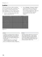
Lathe 138
Taper 140
Twist 141
Bend 142
Smooth Scale/Move Plus 143
Rail Extrude — Single Rail 144
Rail Extrude — Multiple Rails 149
Rail Bevel 151
Edge Tools 153
Add Edges 153
Reduce Edges 155
Remove Edges 155
Rounder 156
UV Texturing 165
Chapter 6 Architectural Modeling Exercise: Interior Set 174
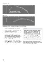
Floor Plan 174
Two-Point Polyline Work 175
Chapter 7 Modeling 3: Sub-Patch Organic Modeling 197
Smooth Shift 199
BandSaw 200
Magnet 203
Pole 204
Vortex 204
Subdivision Order 205
Chapter 8 Organic Modeling Exercise 1: “One-Minute”
Spaceship 208
·························
Contents
vii
Chapter 9 Organic Modeling Exercise 2: Character Body 214
Torso 214
Arms and Hands 216
LegsandFeet 224
Finishing Touches 232
Chapter 10 Organic Modeling Exercise 3: Head Modeling 236
Reference 238
Chapter 11 Organic Modeling Exercise 4: Modeling a
Wolf’s Head 259
Chapter 12 Modeling 4: Spline Modeling Basics 270
The “Rules of the Game” 270
Three-Curve Patches 271
Four-Curve Patches 275
Chapter 13 Spline Modeling Exercise: Kayak 278
Chapter 14 Spline Modeling Exercise 2: Modeling a
Human Head 292
Poly Count and Flow 293
Poly Count 293
Poly Flow 294
Spline Modeling Pitfalls 296
Spline Modeling Tips and Tricks 297
Creating the Cage 298
Patching Tips and Tricks 335
Patching the Cage 337
Basic Detailing 344
Polygon Reduction 350
Advanced Detailing 358
Closing Thoughts 379
Chapter 15 Layout 2: Animation Basics 380
Keyframes (Keys) 380
“Motion” Graph Editor 385
Adjusting Timing 388
Previews 394
Rendering an Animation 395
Chapter 16 Layout 3: Character Animation 398
A Brief Introduction to Character Animation 398
Bones and Rigs 398
Inverse Kinematics, Forward Kinematics, and IK Booster . . 399
FK (Forward Kinematics) 399
Contents
························
viii
IK (Inverse Kinematics) 400
What Is IK? 400
“Standard” IK Basics 400
“Standard” IK Hazards 407
“Standard” IK Rules 415
IK Booster 416
Applying IK Booster 416
Long Chain Dependability 418
IK Booster and Movement 419
IK Booster and Keyframes 419
Pose and Motion Saving and Loading 421
Quaternion Rotations 422
Keyframe Move Mode 423
Newbie Sensory Overload 424
Chapter 17 Layout 4: Special FX 425
Glow Effect 425
Glow Effect Basics 426
Fake “Volumetric Lights” 429
Lens Flares 434
Compositing 440
CG Elements onto a “Live-Action Plate” 440
Basic Explosions 449
Chapter 18 Simulations 1: HyperVoxels and Particles 459
HyperVoxels 459
HyperVoxel Explosion 459
HyperVoxel “Surfaces” 466
HyperVoxel “Sprites” 471
Particles 477
Conclusion 481
Chapter 19 Simulations 2: Dynamics 482
An Introduction to Dynamics 482
Personal Dynamics 483
Social Dynamics 483
Relational Dynamics 483
The Dynamics Community 484
Dynamic Decisions 485
Applied Dynamics 486
Collision Effects 486
HardFX 489
ClothFX 499
SoftFX 504
·························
Contents
ix
Chapter 20 Simulations 3: Fur and Hair 510
An Introduction to SasLite 510
Beyond the Basics 514
Creating a Rug 514
There’s Nothing Plain about This Grassy Plain 521
Hair’s Where It’s At! 523
Refining the Beard and Mustache 528
Creating Hair with Long Hair Guides 531
Splitting Hairs to Work with SasLite’s Limits 543
Rendering the Hair 544
Long Hair Guides, the Sequel! 545
Eyelash Settings and Refinements 552
Making Eyebrows 553
Tips for SasLite Eyebrow Settings 555
SasLite vs. Sasquatch 556
Time-Saving Features 556
Sasquatch’s Valuable Extra Features 559
Epilogue 565
Appendix A Plug-ins and Programs 567
Appendix B Resources 590
Appendix C LightWave’s Default Hot Keys 602
Index 607
Contents
························
x
Introduction
What you have in your hands is, quite sim
-
ply, a collection of tools and techniques that
many professional LightWave artists use
every single day doing what we do in our
various fields. The tools and techniques
explored in this book are essential to cr eat
-
ing the caliber of imagery that you see on
film and television and in print and video
games.
While this book contains no “secrets,”
per se, it does strip away the techno-babble
that plagues so many technical documents
and reveals easy-to-follow, industry-proven
techniques. These are techniques that you
would eventually pick up on your own, as
did the rest of us. However, the average
learning curve for “discovering” them on
your own is estimated at between five and
eight years (much less if you find yourself
hired into a studio where you are working
on actual productions).
The information in this book is designed
to get you up and running with the software
as quickly as possible. The first few chap
-
ters will orient you to LightWave’s unique
interface. The next several chapters focus
on lighting and surfacing techniques. Sub
-
sequent chapters develop your modeling
skills and teach you the basics of animation.
The final chapters show you how to add
“pizzazz” to your work with special effects
and dynamics simulations. The files for the
tutorials discussed in this book can be found
on the companion CD-ROM. When
available, both PC and Mac versions have
been included.
Obviously, the information contained in
this book may seem overwhelming, espe
-
cially if this is your first foray into 3D. In
the immortal words of Douglas Adams,
“Don’t panic!” This book will provide you
with a solid foundation in LightWave. It
comes from those with many years of expe
-
rience who still have the passion of those
newly introduced to the art form!
From this foundation you will discover
new things, find better solutions, and gen-
erally raise the bar for us all. Show us the
dreams you’ve got in your head, the things
that you wished you could always see but
didn’t know quite how to bring to life. Share
those dreams that wer e so exciting they
kept you awake at night. Share these things
with the rest of us, post them on forums,
feature them on web sites, and show them
in film festivals. Help to inspire the rest of
us by sharing what moves you in ways
words can never r elay!
Welcome to the path! May your journey
be one that fills you with wonder and
excitement, far exceeding what you barely
dare to dr eam possible.
—Timothy Albee
—Steve Warner
xi
This page intentionally left blank.
Chapter 1
Playing in Three
Dimensions
Before we get really deep into the nuts and
bolts of the major LightWave tools, we’ve
got to make sure everyone is on the same
page about understanding the core concepts
of 3D. Math and geometry figure heavily in
these core concepts, but they come into
play in such a way that they’re fun. (This is
probably because when working in 3D,
math no longer represents abstract, almost
arcane, concepts. In 3D, math and geometry
are almost tangible. They give you immedi-
ate gratification with imagery that looks
awesome when you solve whatever prob-
lem you’re working on.)
Note
If kids were taught math and geometry with
3D (making movies or exporting animations
into a public domain game engine), you
couldn’t keep them away from it.
Using 3D, you not only see an immediate
use for all that nifty trigonometry, geome-
try, tensor calculus, and algebra, but you
also have a lot of fun playing with it (yes,
playing)! So, as you explore this, keep in
mind that the whole objective is to have
fun, explore, and play. If you keep that focus
in mind, the nuts and bolts will be almost
effortless.
3D “Space”
To measure any three-dimensional object,
whether it be in “real” space or the “virtual
world” of a computer, you need to attribute
to that object three dimensions. In the real
world, these three dimensions are most
commonly thought of in terms of length,
width, and depth.
So, a “dimension” is really just a vector (a
line that extends infinitely in each direction
from its origin, never turning and never
stopping) laid along a specific axis (the
angles that define the vector’s orientation).
Height is a dimension, just as width and
depth are. But the labels “height,” width,”
and “depth” are too subjective to be used
with any certainty within the precise areas
of mathematics, drafting, or computer-aided
design. Certain conventions (agreements
that, to make things easier for everyone, a
certain symbol will always represent a cer
-
tain concept) were brought into play for the
defining of these three dimensions as they
exist within the conceptual space of a
computer.
In three-dimensional space, up and down
are defined as parts of the Y axis. The area
above the ground plane (defined where
Y=0) is measured with positive values (like
Y=5). Below the ground plane, the Y axis is
measured with negative values (like Y=–5).
Left and right are measured along the X
axis. Space to the left of X=0 is measured
1
with negative values, and space to the right
of X=0 is measured with positive values.
Space “away from you” is measured with
positive values of the Z axis, and space
“toward you” is measured with negative
values of the Z axis.
Bear in mind that like the image in Fig-
ure 1-1, your viewport (your window into
this “virtual world,” of which you may have
more than one open) may be offset from
what the computer considers “world-
space.” World-space is easy to think of as
LightWave’s “handle” on its reality. No mat
-
ter how you spin an object, no matter how
you rotate a viewport, LightWave will
always keep X=0, Y=0, and Z=0 exactly
where it always has been (and forever will
be). So, like in Figure 1-1, the viewport can
be rotated counterclockwise a bit and tilted
up just a bit so you can see the axes all
nicely laid out before you, but LightWave’s
handle on where +X becomes –X will
never vary.
For keeping track of how an object is
rotated within three-dimensional space,
LightWave has taken its labels for the rota-
tion axes from what you’d think of while
flying a plane: H
eading, Pitch, and Bank.
Figure 1-2 is probably confusing. Let me
take a different angle on the concept.
If you think of your hand like an airplane
(I know it’s simplistic, but bear with me),
heading is the axis that would change your
compass direction, pitch is the axis that
would raise and lower the nose of the air
-
plane, and bank is the axis that would get
the plane to roll on its side. It may seem
silly, but for the first couple of years that I
worked in 3D, I still did the “my-hand-is-
an-airplane” thing to figure out rotation
axes. (Hey, if it works, don’t knock it!)
Chapter 1
························
2
Figure 1-1: The convention for defining
three-dimensional space.
Figure 1-2: Heading (H) rotates around the Y axis.
Pitch (P) rotates around the X axis. Bank (B) rotates
around the Z axis.
Objects
Behind every slick render — hidden under
the fur, buried within the volumetrics, deep
within the polish of the texturing — is an
object. At its core, the object is made up of a
meshwork of lines that define triangles,
quadrangles, or other variously shaped
polygons.
The quickest way to understand the con-
cept of what 3D is all about is to think of
papier-mâché laid over a chicken-wire
mesh. The papier-mâché surface may have
all sorts of paint and whatnot on it (giving it
the appearance of anything from flesh to
rock), but at its core is a carefully planned-
out wireframe structure. That structure is
what we would consider the object.
LightWave has very few limitations as to
what it can “conceptualize” as an object. If
you wanted to have a single polygon (a
closed plane bounded by straight sides)
defined by 500 points, you could. (Many
other programs restrict the user to building
only with triangles.) LightWave also allows
you to build using splines (spatial-lines,
originally thought up for designing cars) and
a wonderful hybridization of splines and
polygons known as sub-patches (also known
as “subdivision surfaces” in other software
packages).
The toolset that this combination of
polys, splines, and sub-patches offers
means you can create extremely complex
geometric or organic
shapes with amazing
speed. We get into using
each one of these differ
-
ent tools in a bit. But
how can you see what
you’ve built without
light?
················
Playing in Three Dimensions
3
Figure 1-3: LightWave’s rotation axes — think of your hand like a plane.
Figure 1-4: Beneath the 3D fur (generated with
Worley Labs’ Sasquatch) is a model made up of
thousands and thousands of triangles.
Figure 1-5: The same sphere can look completely different with different
surfacing treatments.
Virtual Lights
Without light, we would see nothing. The
same applies to the virtual world within
LightWave. In order to “see” anything in
LightWave, you must (in essence) use one
of LightWave’s lights to send a “wavicle”
(a wave/particle of light) scattering off the
surface of an object and into the lens of
LightWave’s camera. (When you think of
your eyes as cameras, this is exactly the
way things operate in real life.)
Each of the lights within LightWave has a
real-world counterpart. A distant light is like
a light that is so far away that its rays all
behave as if they are parallel to one another.
This is like sunlight or moonlight or nonde
-
script “bounced” lighting. Distant lights can
cast shadows, but they only cast hard-edged
ray-traced shadows (shadows that are per
-
fect in every detail except that they are also
perfectly sharp).
Distant lights give a
flat, almost “spacey”
kind of feeling.
They’re great for
when you want to
imply that light has
traveled great dis-
tances to impact the
objects (like from the
sun, moon, or distant
stars). Distant lights
that don’t cast shad-
ows are also great for
precisely suggesting
ambient light (more on
this in Chapter 4).
Point lights are like
candles or non-frosted
“globe” lightbulbs.
Like distant lights,
point lights can cast
only hard-edged,
ray-traced shadows.
Point lights cast
their light from a sin
-
gle point. Notice how
you don’t actually see
the light itself but only
the impact of the
light’s waves. (If you
wanted to see a light
“bulb,” you would
Chapter 1
························
4
Figure 1-6: The different kinds of lights available to a LightWave artist.
Figure 1-7: Distant light.
Figure 1-8: Point light.
build a model of one and “attach” the light
to the lightbulb object.)
Spotlights are like the klieg lights used
on live-action productions. They cast a cone
of light in only one direction and can fade
that light gently from the light’s “hot spot”
to the edge of its cone. Spotlights can cast
hard-edged, ray-traced shadows, and they
can also cast soft-edged (but technically
imperfect) shadow-mapped shadows, which
are much quicker to calculate than
ray-traced shadows. These are the most
commonly used light. They’re fast, predict
-
able, and versatile.
Linear lights are like fluorescent tubes.
They cast only ray-traced shadows, but
these shadows are soft-edged. The amount
of softness in the shadows from linear lights
is determined by how long the “fluorescent
tube” is and how far away it is from the
objects casting or receiving shadows (just
like a “real” fluorescent light). These lights
give a soft, gentle glow. Their shadows take
longer to calculate than shadows from dis
-
tant, point, or spotlights,
but not as long as shad
-
ows from area lights.
Area lights are a little
like spotlights in that
they cast light in
roughly a cone shape.
But this cone lacks the
controls given to spot-
lights, and light is given
off both in the direction
the light is facing and
directly behind it. Area
lights most closely sim-
ulate real-world lights
and shadows. They are
slow to render, even
when they are not cast
-
ing shadows, so use
them sparingly.
As LightWave has
progressed from version
to version, its lights and
renderer (the complex
engine that calculates
how everything looks)
have been updated to
allow light to behave
more and more like light
in the real world. Light
can now bounce off sur
-
faces (giving the same
················
Playing in Three Dimensions
5
Figure 1-9: Spotlight.
Figure 1-10: Linear light.
Figure 1-11: Area light.
kind of red hint when an apple is placed
right next to a white wall). And light can
now obey the laws of caustics, meaning that
light “wavicles” will be refracted (focused)
through transparent objects (like sunlight
through a magnifying glass) and reflected off
shiny objects (like a gold ring throwing a bit
of brightness onto the stone plinth that
holds it).
So, the important thing to remember
when lighting your scene in LightWave is to
think, “How would I light this in real life?”
(Those of you who have studied
photography or directed live-action film or
theater have a distinct advantage in under
-
standing lighting. When a room is lit for a
production, it is lit differently than how it
would be lit for general use. Studying how
theatrical and cinematic lighting is
accomplished could not be more strongly
recommended.) As you walk around your
world, always look for how the environ
-
ments you are moving through are lit. Then
think about the slight changes to the
real-world lights that you’d have to make to
get the same effect within LightWave.
Virtual Camera
LightWave’s “cameras” are the windows
through which your audience will see your
final product (you can have up to 100 cam-
eras in a scene). All of LightWave’s other
windows are aids in constructing your work;
the camera’s viewport is the one window
where you will showcase your work.
When you tell LightWave to render, what
-
ever the camera is “seeing” will be fair
game for the renderer to draw. The camera
can be moved and rotated along all axes. It
can track to items in the scene and inherit
its motion directly from other items (it
could be “parented” to the wingtip of a
plane if you wanted). There are more set-
tings on the LightWave camera than most
of us will ever need — though it is wonder-
ful to know that they’re there, just in case
we ever do.
Figure 1-13 has Show Safe Areas active,
which gives me two sets of lines running
around the outside edge of the renderable
area. Even modern televisions cut off much
of the picture. The outer line is known as
“Action Safe” and shows where you can
safely assume that any important action
won’t be cut off by a viewer’s TV set. The
inner line is known as “Title Safe” and
marks the extents of where important text
or logos should go — just in case the
viewer’s TV is really old and crops that
much off the picture.
The partially gridded cross that looks
like it could be in a submarine’s range
finder is what’s known as a field chart.For
traditional animators, a field chart helps cal
-
culate panning shots (shots where the
background is moving), but for 3D, it is
Chapter 1
························
6
Figure 1-12: The camera icon serves as a visual
representation for the camera’s position and
rotation within three-dimensional space. It also
reflects the camera’s field of view, its focal distance
(what will be in focus when using depth of field),
and where objects begin to disappear into
LightWave’s fog.
used mostly as a reference guide for ele-
ment placement.
···
With those basic concepts, that’s about all
there is to 3D! Everything else is just about
finding new ways of putting things together.
Your greatest assets are creativity, prob
-
lem-solving skills, and a darn good sense of
humor.
················
Playing in Three Dimensions
7
Figure 1-13: The Camera view. The areas shaded with tan on the
left and right of the viewport are indications of what is outside the
camera’s 640x480 field of view.
“If you nail together two things
that have never been nailed
together before, some
schmuck will buy it from you.”
— George Carlin
Note
While LightWave’s camera has, literally, no
strings attached and though you could do
things with that camera that would be
impossible with a real camera, just keep in
mind that audiences have built up almost
100 years of experience watching the
results of real cameras. I find that unless
there’s a darn good reason to have a “fly-
ing” camera, the story you’re telling is
served much better with the camera han
-
dled as if it were on a virtual tripod.
Chapter 2
LightWave
Dissected
I’d like to take a moment to point out that
while this book may cover a great many
things, it isn’t trying to be the LightWave
manual. Its focus is that of being a “kick-
bootie” introductory course that will be a
bit like a “rail-gun” in getting you some
serious momentum on your way to becom
-
ing one of the great LightWave jockeys.
There are quite a few commands, tools,
and windows that I don’t cover at all (some
because they should be self-explanatory
once you get the hang of things, and others
because in an introduction to LightWave,
they’re just too much information). There
are others I go through step by step,
explaining all the whys and wherefores that
you need to not just be parroting my
actions; you’ll learn how LightWave
“thinks.”
Once you understand how to correctly
phrase the question, the answer almost
completes itself.
Some of the real “gold” in this book is
the collection of secrets, tips, tricks, and
techniques I’ve discovered over the years.
(A few of these are new discoveries I’ve put
together over the past few weeks — Light
-
Wave is always showing you new things if
you’re willing to see. No matter how good
you think you are, remember that you are
always and only just scratching the surface
of the power contained within LightWave.)
LightWave makes use of the idea of
“separation of power” better than any other
3D package I’ve used. In Modeler, you
sculpt your objects; in Layout, you lay them
out to create your scene.
If you’ve worked with 3D packages in
which you have to fight with modeling the
details on an object while it is encroached
upon on all sides by other items in a scene,
modeling in one environment and animating
in another might seem almost too easy. But
the first time you have to tweak an object
buried within a packed scene, you will love
the fact that Modeler lets you isolate that
object in its rest position without anything
else (objects, deformations, or the like) get-
ting between you and the exact shape that
you’re looking for.
When “dissecting” LightWave, it can
first be separated into two major elements:
Modeler and Layout.
•
Modeler is where objects are
“sculpted” using a set of comprehensive
tools. For almost anything you need, Light
-
Wave’s Modeler seems to have a tool that
does just that, as there are many tools to
explore. Play with them all and get to know
them so that when you need something,
you know where to look.
•
Layout is where the objects that
you’ve sculpted are lit, animated, and ulti
-
mately rendered for their final presentation.
8
LightWave also integrates other programs
that support both Layout and Modeler. We
touch on each of these as we go through
this chapter.
•
The Hub conducts the flow of informa
-
tion between Layout and Modeler.
•
Plug-ins are separate programs that
attach to LightWave, “LEGO
®
-like,” and
boost the functionality of Layout and
Modeler.
•
LScript is the scripting language
through which the end user has complete
control over every aspect of LightWave.
•
LWSN is LightWave’s ScreamerNet,
the free network renderer that allows you to
use nearly every computer in your estab
-
lishment to help render your animations.
Modeler
Modeler’s default tool/window layout fea-
tures four viewports (Top, Perspective,
Back, and Right), a collection of commands
and information readouts on the bottom of
the screen, a set
of tools on the
left-hand side of
the screen, and a
series of tabs
that offer differ
-
ent sets of these
tools.
···················
LightWave Dissected
9
Figure 2-1: LightWave’s Modeler (as seen from a screen resolution of 1024x768).
Modeler houses all the tools you need to build the objects you will animate in
Layout.
So, in its simplest sense, you model in
Modeler, and lay out the models in Layout.
Though both Modeler and Layout have
been crafted and refined over the years to
be the optimal environment for doing what
they each need to do, they are both star
-
tlingly similar in many respects. Everything
else pretty much functions behind the
scenes; you could spend an entire career
with LightWave and never do more than add
plug-ins you find freely available over the
Internet (mondo thanks to the wonderful,
supportive, and blisteringly intelligent
LightWave user/support base out there).
But should you want to “pop the hood” and
“trick her out,” with LScript and Light
-
Wave’s open-ended functionality, there is,
quite literally, no limit to what you can do.
Viewports and Viewport
Controls
Each window that shows a different angle
on the model that you’re sculpting is known
as a viewport. Each viewport is completely
customizable, as is the number of viewports
and their relationship to one another. By
referencing your work at different angles,
you can be assured that you will always be
able to isolate the exact point or poly you
want to manipulate, even amid a complex
model like the one shown in Figure 2-1.
Newbie Note
A pop-up menu in LightWave is indicated by a
small downward-pointing triangle next to a
tool or button. (You can see two next to Top
(XZ) and Wireframe in Figure 2-2, the first
pertaining to the viewport angle (or view
angle) and the second being a separate con
-
trol that lets you choose the level of real-time
rendering the viewport should display.) These
triangles let you know that there are more
options than what is shown. Clicking on a
pop-up menu presents you with a list of other
options from which you can choose.
Clicking on the View Angle pop-up menu
lets you choose which kind of view you
want that viewport to display. In Figure 2-3,
you see that Top (XZ) is highlighted, show
-
ing that it is the active choice.
The pop-up menu to the right of the
View Angle pop-up menu lets you choose
what level of real-time rendering you wish
to apply to that viewport. In Figure 2-3, you
can see that Wireframe is highlighted, reit
-
erating that the viewport’s current display
type is Wireframe.
Chapter 2
························
10
Figure 2-2: The View settings, located in the
upper-left corner of each viewport, let you quickly
set that viewport’s angle and display type.
Figure 2-3: The View settings pop-up menus.
Figure 2-4: The Color Wireframe display type
reflects the polygons’ Sketch Color attribute.
Figure 2-5: The Hidden Line display is similar to
Wireframe; however, only the polygons facing the
Perspective view’s camera are displayed. Other
polys are hidden, making it easier to edit the object.
···················
LightWave Dissected
11
Figure 2-6: The Sketch display type lets you see
your object as a solid, wireframed object that
doesn’t show any kind of lighting or surfacing
attributes. Sketch does, however, show polygons’
Sketch Color attribute.
Figure 2-7: Wireframe Shade is a lot like Sketch
in that you see the polygons outlined in their
respective Sketch Color. However, Wireframe
Shade also shows surface coloring and the
rudimentary lighting that Modeler uses to help you
figure out the direction each poly is facing.
Figure 2-8: Flat Shade shows your model as a solid
object without any kind of smoothing going on
between polygons; that is, each poly comes to a
sharp edge when it meets its neighbor, regardless
of its smoothing settings. (More on smoothing in
Chapter 3.)
Figure 2-10: The Weight Shade display type shows
the effect that weight maps will have on your
model. Here, we’re looking at the weight map for
the husky’s head; the bright red that indicates
100% influence dissipates into “circuit-board
green” that indicates 0% influence.
Figure 2-11: The Texture display type loads in any
image-based textures you may have applied to
your model and maps them accordingly. This husky
is sporting a simple UV texture map. (See Chapter
4 for more on texture mapping.)
Figure 2-9: Smooth Shade shows your model with
all its surface smoothing settings considered. (I’ve
activated the sub-patches, which bring into play a
complex smoothing algorithm on the model’s
geometry itself. More on sub-patches in
Chapter 7.)
In addition to the controls that change the
viewport’s angle and its display type, the
top of every viewport has four control but-
tons that let you move, rotate, zoom, and
minimize or maximize the view.
Clicking and dragging on the Pan button
scrolls the viewport around so you can cen
-
ter in on different things. (All viewports
that do not have Independent Center
checked under Modeler | Options | Dis
-
play Options will also move when you pan
Modeler’s center about. More on this later
in the “Modeler Display Options” section.)
Clicking and dragging on the Rotate but
-
ton orbits a Perspective viewport around its
center. (This button is inactive in non-per
-
spective views.)
Clicking and dragging on the Zoom but
-
ton zooms in and zooms out on the view’s
current center (as with Pan, all viewports
without Independent Zoom selected will
respond). Drag to the left to zoom out, and
drag to the right to zoom in.
Clicking and dragging on the Min/Max
button toggles the viewport in and out of
full-screen mode.
Note
Hot keys (or keyboard shortcuts) let you get
the job done as quickly as possible, with an
absolute minimum of mouse-clicking and
hoop-jumping.
When I mention the hot keys I use (almost
without thinking anymore), I’ll set them off
in a special “Hot Key Block,” as follows.
(Remember that LightWave’s hot keys are
case sensitive! If you’re having trouble, check
to make sure that Caps Lock isn’t on.)
Hot Key Block
Viewports
<g> centers your view around the current
location of the mouse. You can use this to
cover great distances (like when you’re in
close working on your character’s foot and
want to zip to his shoulder without having to
zoom out, recenter, and zoom back in).
<,> (comma) zooms out by a factor of 1.
<.> (period) zooms in by a factor of 1.
<Shift> + <,> zooms out by a factor of 2.
<Shift> + <.> zooms in by a factor of 2.
<Ctrl> + <Alt> and dragging in a view
-
port zooms in and out, just like clicking and
dragging on the Zoom button (Figure 2-16).
<Alt> and dragging in an orthogonal
viewport (any view that isn’t a Perspective
view) scrolls that viewport in the direction
you drag the mouse.
<Alt> and dragging in a Perspective
viewport orbits the view around its center.
<Shift> + <Alt> and dragging in a Per
-
spective viewport scrolls (pans) it in the
direction you drag the mouse. (In an orth
-
ogonal view, this works just the same as
<Alt> dragging.)
Chapter 2
························
12
Figure 2-13: These tools control the position,
rotation, zoom, and size of the viewports.
Figure 2-14:
Pan button.
Figure 2-15:
Rotate button.
Figure 2-16:
Zoom button.
Figure 2-12: Textured Wire display combines
Texture and Wireframe Shade displays, giving you
the best of both worlds. Your object will show
image-based textures and rudimentary lighting
along with wireframes rendered according to each
polygon’s Sketch Color.
Figure 2-17:
Min/Max button.