hugh piggott - windpower workshop building your own wind turbine
Bạn đang xem bản rút gọn của tài liệu. Xem và tải ngay bản đầy đủ của tài liệu tại đây (9.78 MB, 157 trang )
Windpower
Workshop
Hugh Piggott
Foreword
by
Tim Kirby
British
Wind
Energy
Association
Windpower
Workshop
BUilding
Your
Own
Wind
Turbine
Hugh
Piggott
4'~
Centre for
ill
I Alternative
~
l't
Technology
••
, Publications
The
Author
Hugh
Piggott
runs
his
own
successful
windpower
business
from
his
home
on
the
beautiful,
appropriately
windswept,
peninsula
of
Scoraig, off
the
coast of Scotland. There
he
advises
individuals
and
companies
at
home
and
abroad
on
small
to
medium
scale
windpower
turbines
and
systems.
He
has
been
making
windmills
for
twenty
years
from scrap
parts
and
teaching others
how
to
do
so,
for example
on
the
Centre for Alternative Technology's twice-
yearly
windpower
course. His
books
are
amongst
the
Centre's
best
sellers.
He
has
a wife
and
two
children.
He
has
also
written
It's A
Breeze!
A
Guide
to
Choosing
Windpower,
Scrapyard
Windpower
and
Choosing
Windpower for C.A.T. Publications.
Contents
The
author
Foreword
Chapter
One: A
Wild
Resource
The
wind:
a
wild
resource
No
free
lunch
The
environmental
cost
How
much
power
can
you
expect?
Efficiency:
where
does
the
energy
go?
Design
basics
Summary.
Chapter
Two: Safety
Electrical safety
Protection
against
fire
Protection
against
shock
Battery
hazards
Other
responsibilities
Chapter
Three: Rotor
Design
Betz Revisited
Using
lift
and
drag
Blade
design
Upwind,
downwind
or
vertical axis
Conclusion
Chapter
Four: Blade
Making
A
word
of
warning
Blade
weight
Blade
materials
How
to
carve a
set
of
rotor
blades
Painting
and
balancing
the
blades
Chapter
Five:
Generators
What
to
look
for
How
generators
work
Changing
the
speed
of
generators
Types
of
generator
Motors
used
as
generators
Building
a
permanent
magnet
alternator
from
scrap
Design
hints
In
conclusion
3
6
8
8
9
10
11
13
16
20
21
21
21
23
26
27
30
30
33
38
42
47
48
48
49
49
50
60
63
63
64
78
79
84
86
92
95
Chapter
Six:
Mechanical Controls
Facing into the
wind
Avoiding over
load
Turning
away
from
the
wind
Shut
down
systems
Chapter Seven: Electrical Controls
Load control:
the
key
to
good
performance
Heating systems
What batteries like
best
Chapter Eight: Towers
Types of
tower
How
strong is
strong
enough?
Erection
Hands-on
tower
erection
Guy materials
Anchors
Hints for safe erection of tilt-up
towers
So
we
come to
the
end
Glossary
Windpower Equations
Worked Examples
Access Details
Index
96
97
99
101
105
109
109
110
115
120
120
120
121
123
125
128
134
137
139
146
148
153
157
Foreword
Windpower
~ites.
It's
one
of those multi-faceted subjects
which
appeals to all sorts of
people
from
all sorts of angles - free
power,
no
environmental
costs,
not
to
mention
a
world
of
opportunity
for
the'
gadget'
folk. But
what's
it
all about,
and
what
can
practically
be
done?
Although
wind
is
one
of
civilisation's
oldest
forms
of
mechanical
power,
it suffered
something
of a relapse
from
the
start
of this
century
as
the
benefits of
mass
cheap
energy
supply
came
through. But as
the
true
(and
horrendous)
costs of
mass
fossil fuel
use come to light,
wind
is
making
a
big
comeback, particularly
with
large
grid
connected
turbines
in
Europe. A
growing
number
of countries are
doing
their
best
to
encourage
wind
energy
gener-
ation as
part
of a
range
of vital
measures
towards
sustainability.
Although
it
may
seem
contrary
to
'green'
thinking,
in
many
ways
the'
grid'
is a
useful
environmental
tool-
it allows
one
area's
surpluses
to
meet
another
area's
needs. This avoids
much
of
the
costly (economically
and
environmentally
speaking)
requirement
for
energy
storage -
common
in
most
small
'off
the
grid'
systems.
If
we
all
wanted
to
use
autonomous
wind
energy
with
battery
storage,
we
would
run
out
of
lead
before
we
got
very
far!
But
there
certainly are places
where
the
grid
does
not
reach,
and
plenty
of
people
wanting
to live
in
them. Scoraig, Hugp. Piggott's
base
in
Scotland, is
just
such
a place.
With
a
healthy
community
heading
for a
hundred
souls
(an
achievement
after
total
abandonment
by
the
old
crofting
community
in
the
1950s), all off
the
grid,
and
many
with
their
own
small windmills, it
has
been
the
perfect place for
earning
the
experience
and
reputation
as
the
best
there is in 'DIY'
windpower.
Wind can
be
an
excellent choice for isolated
power
supply,
and
such
is
the
nature
of
the
folk
who
live
in
such
places
that
many
will
prefer to 'DIY'
wherever
possible. This
book
does
an
admirable
job
in filling a
gaping
hole
in
the
available literature
on
practical small
scale
wind
engineering. It comes
from
a disciplined
and
highly
trained devotee
who
has
explored
all
the
angles
and
learned
most
of
the lessons
(many
of
them
the
hard
way).
Wind
is
no
more
simple
than
it is free (again economically
and
environmentally
speaking),
and
a
guide
is
most
recommended.
There are
plenty
of
pitfalls, most of
them
easily avoided.
The
rew~rd
is
that
wind
is
the
closest
thing
to
being
able to
'magic' clean
energy
from
thin
air,
and
Hugh
Piggott is a
true
guru
of
the art. Read
on
and
enjoy.
Tim
Kirby
Chairman
British Wind Energy Association
8 Windpower
Workshop
Chapter
One
A
Wild
Resource
This
book
is
written
for those
who
want
to
build
their
own
windmill,
and
also for those
who
love to dream. It
was
inspired
by
the
windpower
course
at
the
Centre for Alternative Technology,
an
event
where
folk from all
backgrounds
come
together
to
share
the
excitement of learning
about
windpower.
Much
has
been
omitted
for lack of space,
but
you
can
find
it
elsewhere. For basic
knowledge
of electricity, forces,
and
turning
moments,
look
through
a school physicsbook. For details of
how
to site a
windmill
and
live
with
windpower,
see the
companion
volumes
called It's a
Breeze
and
Off
the
Grid
(also available from CAT Publications).
The
wind: a
wild
resource
Wind
energy
is
wild
stuff,
and
very
tricky to handle.
Capturing
wind
energy
is like
riding
an
antelope,
when
we
could
be
using
a
Volkswagen.
Most
newcomers
to
wind
energy
underestimate
the
difficulties.
Do
not
expect to
get
much
useful
power
from a small
windmill
in
a
suburban
garden,
nor
to
knock
together a reliable
windpower
system
in
an
afternoon!
Look
hard
at
the
size of
wind
machine
needed
to
produce
the
energy
needed.
Is this a realistic project for you?
Do
you
have
the
workshop
facilities?
Do
you
have
access to a suitable site,
where
there
is
space
to
allow
the
machine
to
operate
safely
and
unobstructed?
A Wild Resource 9
If
your motivation is to clean
up
the
environment,
then
small
scale
windpower
is
not
necessarily
the
best
approach. Insulating
your house
may
well save
more
energy. If
you
are
an
urban
supporter of renewable energy,
you
can
ask
your
local electricity
board about their
green
tarriff,
or
devote yourself to
winning
the
environmental
debate
on
wind
farm
acceptance.
But if
you
have
the
time,
the
workshop,
the
site,
and
the
passion,
then
you
will
build
a windmill,
and
enjoy
the
hard-earned
fruits. I
hope
this
book
helps.
Be
careful.
No
free lunch
. The
wind
is free,
until
the
government
manages
to
put
a tax
on
it, and
many
people
assume
that
wind
energy
will therefore
be
a
bargain. If
that
were
so,
then
we
would
see
windmills
everywhere,
but of course
'there
is
no
such
thing
as a free lunch'.
Wind is a
very
diffuse source of energy. To
produce
useful
amounts of power,
windmills
need
to
be
large; to
work
efficiently
and reliably
they
need
to
be
well
engineered.
So
they
are
expensive. If
you
build
your
own,
you
can save
most
of
the
cost,
but spend a great
deal
of
your
valuable time.
Battery depreciation
Power from small, stand-alone wind-electric
systems
using
batteries is
not
likely to
be
cost-competitive
with
power
bought
from the national
grid
in
the
near
future. Even
the
cost of
the
batteries can rule it out. Batteries
may
last
about
seven
years before
they are
worn
out. It
has
been
calculated
that
just
the
cost of
replacing the batteries can
be
roughly
the
same
as
the
cost of
buying the same
amount
of
power
as
the
system
produces
in
this
period, from the
mains
supply.
This comparison highlights
the
fact
that
battery-wind
power
is
not likely to
be
viable
in
the
city. (There are
other
reasons,
such
as
low windspeeds, turbulence,
and
the
fury of neighbours.)
In
remote places, the cost of installing
and
maintaining
power
lines
may be greater
than
that
of
the
windpower
system, so
windpower
becomes a more economic
and
reliable source
than
the
mains.
10 Windpower Workshop
Pay
less
and
get
more from the scrapyard
I
am
a
frequent
visitor to
my
nearest
non-ferrous metals dealer,
where
I collect cable, batteries, steel for welding,
sheet
aluminium,
etc.
Using
scrap materials will
not
necessarily
reduce
the
quality of
the
job. You
can
afford to
buy
something
much
heavier
from
the
scrapyard
than
you
could
afford to
buy
new. For example, it
was
once possible to
obtain'
scrap'
batteries
from
telephone
exchanges.
I
have
used
them
for
ten
of
their
twenty
year
lifetime. If I
had
bought
new
batteries, I
would
only
have
been
able to afford a small
poor
quality
one.
(However,
use
some
discrimination.
Most
batteries are
scrapped
because
they
are useless, so check
them
carefully
with
a
voltmeter
before buying.)
Everything
in
the
scrapyard
is
there
for a reason,
but
very
often
the
reason
is modernisation. There
may
be
nothing
wrong
with
the
'scrap'
you
buy.
The environmental cost
Every source of
power
has
an
environmental
price.
Windpower
is clean
and
renewable,
but
it
does
have
some
downsides.
At
least
the
pollution
it causes is
here
and
now,
so
'what
you
see is
what
you
get'!
Noise
There are
two
main
kinds
of noise
which
can
arise:
blade
noise
and
mechanical noise. Blade noise is rarely a problem, as it
sounds
similar to
wind
in
trees,
or
flowing streams,
and
is often
masked
out
by
these
very
sounds.
Mechanical noises
can
arise
where
there is
vibration
or
hum
from
the
generator
or
gearbox. These tonal noises
can
drive
people
crazy, especially if
they
are
kept
awake.
Others
(the owners) will !
enjoy
the
music
of
the
windmill
feeding
power
into
the
battery
and
sleep all
the
better!
Visual intrusion
Visual
intrusion
is
even
more
subjective
than
noise.
One
person's
sleek
dream
machine
might
be
another's eyesore. A
windmill
will
normally
be
attractive to
the
owner, especially if self-
built.
Neighbours
may
be
willing to accept it,
but
tact
and
A Wild Resource
11
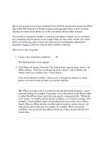
Table
1.1
Instant
Power
Outputs
in
Watts
Windspeed:
2.2m/s
4.5m/s
10
m/s
20m/s
5
mph
10
mph
22
mph
44
mph
Blade
diameter
1m 1 6
70
560
~.!.~.9 ~
9
~9 ~.~~~.~
~.~
~
~?
~
?.9
~/.~.9.9
.
~.!.~.9 ~
9}9 ~.~~~.~
~.~
!
~.9
~~.9
?!.9.9.9
Blade
diameter
4m
12
100
1,
120
9,000
This
table
gives
you
an
idea
of
how
much
power
your
windmill
may
produce.
It
assumes
a
modest
power
coefficient
of
0.15.
For
example,
a
two
metre
diameter
windmill
in
a
ten
metre
per
second
wind
might
produce
280
watts.
Do
not
be
fooled
by
the
apparent
precision
of
the
figure.
In
reality
you
may
get
between
200
and
400
watts,
depending
on
what
'power
coefficient'
you
can
attain.
diplomacy are
very
important
in
gaining
this acceptance.
How
much
power
can
you
expect?
Power (in watts) is
the
rate of
capture
of energy,
at
any
given
instant. Table 1.1
shows
how
much
power
you
can
expect a
windmill of a
given
size to
produce
in
a
given
windspeed.
The
table assumes
that
your
windmill
catches 15% of
the
raw
power
in
the wind. The
percentage
caught
is
known
as
the
'power
coeffi-
cient' (or Cp)
and
we
shall see later
why
it is
such
a
small
a
part
of
the total.
The
raw
power
in
the
wind
depends
on
the
density
of air (about
1.2
kilograms
per
cubic metre),
the
speed
of
the
wind
and
the
size
of
the rotor.
Windspeed
is critical (as
you
can
see
from
the
table).
Stronger
winds
carry a
greater
mass
of air
through
the
rotor
per
second
and
the
kinetic
energy
per
kilogram
of air
depends
on
the
square of its speed, so
the
power
in
the
wind
will increase
dramat-
ically
with
windspeed.
The area
swept
out
by
the
windmill's
propeller, fan, sails,
wings, turbine,
blades
depends
on
the
square
of
the
diameter. We
call
the
windmill
rotor
blade
assembly
the
rotor
for short.
Do
not
confuse this
with
the
rotor
of
the
generator.
At the
back
of this
book
there
are
windpower
equations
which
you can
use
to calculate
the
power
output
of a windmill. Better still,
use a
spreadsheet
to teach
your
computer
to
do
the
sums
for you!
12
Windpower
Workshop
As
you
can
see,
the
power
in
the
wind
varies enormously. There
are only a few
watts
available
in
a light
wind.
It is
not
easy
to
design
a
machine
which
can
convert this
amount
of
power
effec-
tively,
and
yet
survive
the
huge
power
surges
which
arise
during
gales.
The
wind
is always changing,
and
the
power
fluctuations
can
be
extreme. We
need
to
harvest
it
when
it is there,
and
either store it
for
periods
of calm,
or
use
some
other
power
source as a back-up.
In
the
days
of corn-grinding windmills,
the
millers
kept
a store of
grain,
and
ground
it as
and
when
they
could.
Nowadays,
small
wind-electric systems
use
batteries,
which
absorb
surplus
power
during
windy
weather,
and
keep
the
supply
going
during
calm
periods.
A quick guide
to
predicting energy capture
Energy
captured
in
a
given
time is
the
average
power
multi-
plied
by
the
hours. This
depends
at
least as
much
on
the
site as
on
the
machine
itself.
Site conditions
Trees
and buildings
Open fields, with few hedges
Hilltops or coasts (open
sites)
Average windspeed
3
m/s
(6
mph)
4.5
m/s
(10
mph)
6
m/s
(13
mph)
Average
power
output
from a
windmill
is
not
the
same
as its
instantaneous
power
output
when
windspeed
is average. Again,
there is
an
equation
for this
at
the
back
of
the
book.
From
Table 1.2
we
can
see
that
a
two
metre
diameter
windmill
will give
an
average
power
output
of
about
51
watts
where
the
average
windspeed
is 4.5
metres
per
second
(10
mph). These are
just
ballpark
figures: average
output
could
in
reality
be
anything
from 30 to
80
watts.
What
can you power from a windmill?
The average
power
from a
windmill
must
be
matched
up
to
the
average
power
needs
of
the
user(s). The typical
person
(in Europe)
has
an
average domestic electricity
consumption
(at
home)
equiv-
alent to
using
100
watts
all the time. Sometimes
they
might
use
A Wild Resource
13
-Table
1.2
Average
Power
Outputs
in
Watts
Average
windspeed:
3
m/s
4.5m/s
6
m/s
7
mph
10
mph
13
mph
Blade
diameter
1m 4
13
30
Blade
diameter
2m
15
51
121
Blade
diameter
3m
34
115
272
Blade
diameter
4m
60
204
483
many kilowatts,
but
at
other
times
they
hardly
use
anything.
So
for a family of five
an
average
power
of 500
watts
would
be
needed. But it is possible for a family of five to
get
by
using
under
100
watts if they
use
energy-efficiency lighting
with
care
and
avoid
the use of electric
heaters
in
low
windspeed
periods.
Efficiency:
where
does
the
energy
go?
In Tables
1.1
and
1.2
we
assumed
that
the
windmill
would
catch
15%
of the
power
in
the
wind.
In
reality,
the
power
coefficient will
depend
on
how
much
is lost
at
each
stage of
the
energy
conversion
process. Some is
even
lost before
it
can
begin.
Betz's theorem
Albert Betz (1926) is credited
with
figuring this out, so his
name
is
always
used
to refer to this theory.
In order to extract
power
from
the
wind,
it
must
be
slowed
down.
To
remove all
the
wind's
power
would
involve
bringing
the
air to a halt. However, this
would
cause a
pile-up
of
stationary
air
at the windmill,
preventing
further
wind
from
reaching
it. The air
must be allowed to escape
with
some
speed,
and
hence
with
some
kinetic energy (which is lost).
According to Betz,
the
best
power
coefficient
we
can
hope
for is
59.3%,
but
in
practice this figure will
be
whittled
down
further
by
other losses described next.
Drag
The rotor
blades
convert
the
energy
of
the
wind
into shaft
power. Later
we
discuss
the
advantages
of
using
a few,
slender
blades
which
rotate fast,
compared
with
many
wide
blades,
rotating slowly. Fast
moving
blades
will experience
aerodynamic
14
Windpower
Workshop
'drag'.
Drag
holds
the
blades
back,
wasting
some
of
the
power
they
could
be
catching from
the
wind,
so
we
need
to
make
the
blades
as
'streamlined'. as possible.
Even
the
best
designed
'airfoil section'
blades
will lose
about
10%
of
the
power
they
handle
this way.
Home
built
blades
may
lose a lot more.
Mechanical
friction
There will also
be
friction losses
in
the
bearings,
brushes
and
any
sort
of mechanical drive,
such
as a gearbox
or
pulley
system.
These will
only
increase slightly
with
increasing speed. Therefore
when
the
windmill
is
working
hard,
in
a
strong
wind,
the
friction
losses
may
be
only a tiny percentage of
the
total
power.
But
in
light
winds
friction losses
can
make
an
enormous
difference, especially
in
very
small windmills,
which
have
relatively
low
rotor
torque.
Whether
this is significant will
depend
on
what
is expected
from
your
windmill. If
it
is
your
sale electricity
supply,
it will
be
crucial to
have
high
efficiency
in
light
winds
and
you
should
use
direct
drive
from
the
rotor
blades
to
the
generator,
with
no
gearing
arrangements. Those
who
use
the
wind
for
supplementary
heating
only, for
which
light
winds
are of little use,
may
cut
costs
by
using
a
geared
motor,
or
a
belt
driven
alternator,
which
will
work
well
in
a stiff breeze.
Copper
losses
The
next
stage is to
make
electricity. This takes place
in
the
coils
(or
windings)
of
the
generator. Electric
current
suffers from its
own
kind
of friction,
which
heats
the
wires.
This 'friction' is
in
proportion
to
the
'resistance' of
the
copper
wires carrying
the
current
(see
windpower
equations). You
can
reduce
the resistance
(and
so
the
'copper
loss')
by
using
thicker
wires. This
makes
the
generator
heavier
and
more
expensive,
but
it
may
be
worth
it.
The resistance of a
copper
wire
increases
with
rising
temper-
ature.
Copper
losses
heat
the
coils,
which
increases
temperature,
thereby increasing resistance
and
causing
more
copper
loss. This
vicious circle
can
lead
to
burn
out
in
the
worst
case,
and
will
certainly
lower
the
efficiency of
the
machine, so it will
be
important
to
look
at
the
cooling of
the
generator,
in
the
overall design.
A Wild Resource 15
Copper losses increase
with
the
square
of current.
When
the
generator is
working
at
'part
load',
in
other
words
in
light
winds,
losses in the
main
windings
are
very
small. Some generators also
have 'field coils' (see
chapter
five) carrying
an
almost constant
current. These losses
are
rather
like
the
mechanical
losses
discussed above.
In
light
winds,
they
may
consume
all
the
power
the blades can produce, leaving
you
with
nothing.
Finally,
do
not
forget
about
copper
loss
in
the
cable from
the
windmill. Where the cable is
very
long, it also
needs
to
be
very
thick.
If
the cost of thick cable becomes ridiculous,
then
it is
worth
changing the system voltage.
At
higher
voltages, less
current
will
be needed to
transmit
the
same
amount
of
power.
High
voltage
means much lower
copper
loss
in
cables,
which
is
why
it
is used,
in
spite of the safety
problems
it
may
cause. A
12
volt
system
will lose
400
times as
much
power
as a 240 volt system,
when
using
the
same cable.
Iron
losses
Most
generators
also
suffer
from
iron
losses,
which
are
described
in
detail
in
chapter
four.
Rectifier
losses
Very often, small
windmills
are
built
with
permanent
magnet
alternators,
which
produce
alternating
current
(a.c.). The
power
is
then fed into a battery, for
use
as direct
current
(d.c.). A converter
is
required,
which
changes
the
a.c. into d.c. This is
the
'rectifier'.
Modern rectifiers are simple, cheap, reliable semiconductor
devices,
based
on
silicon diodes. They
work
very
well,
but
like
everything
in
this
world,
they
need
their percentage. (One begins
to
wonder if there will
be
any
power
left
at
the
end
of all this!)
In
this case the rule is simple: each
diode
uses
about
0.7 volts.
In
the
course of passing
through
the
rectifier,
the
current
passes
through
two diodes
in
series,
and
about
1.4 volts are lost.
In
other
words,
to
get
12
volts d.c. out,
we
need
to
put
13.4 volts in. This represents
another energy loss,
representing
about
10%
of
the
energy
passing
through the rectifier.
Again, changing to a
higher
voltage will
reduce
this loss. For
example,
in
a 24
volt
system
the
voltage lost
in
the
rectifier will
be
16
Windpower
Workshop
How
the
Losses
Add
Up
Fig.
1.1
IN
Wind
Power
(100%)
Drag
OUT
the
same
as
in
a 12
volt
system
(1.4 volts),
but
it is
now
less
than
5%
of
the
total.
How
the losses
add
up (or rather multiply)
Each stage
in
the
system
passes
on
a
percentage
of
the
power
it
receives.
We
apply
these
percentages
to
each
other
in
a
row
(Fig.
1.1) to
get
the
overall
power
coefficient. It is
fortunate
that
we
are
starting
off
with
free energy!
Of
course,
there
are
losses
in
any
process. For example,
every
internal
c~mbustion
engine
always
converts
most
of
the
energy
in
its fuel to heat,
seldom
recovered
for
any
useful
purpose.
Design
basics
Match
ing the rotor to the generator
For a
given
size of rotor, it is
tempting
to
use
a
very
large
generator, to
make
use
of
the
high
power
in
high
winds.
But, for a
given
size
of
generator
it
is
tempting
to
use
a
very
large rotor, so as
to
obtain
full
power
in
low
winds.
A
big
generator
with
a
small
rotor
will
very
seldom
be
operating
at
rated
power,
so
it
will
be
disappointing,
especially if
the
generator's
part-load
efficiency is poor. A
small
generator
with
a large
rotor
will achieve full
power
in
low
winds,
giving
a
more
constant
power
supply.
The
drawbacks
are
that
the
larger
rotor
will:
•
need
a
stronger
tower
(chapter 8);
A Wild Resource 17
•
run
at lower
rpm
(next section);
• require more control
in
high
winds
(chapter
6).
The usual compromise is to choose a
generator
which
reaches
full output
in
a
windspeed
around
ten
metres
per
second
(10
m/
s).
See
the first
and
the
fourth
columns
of Table 1.1,
or
the
first
two
columns of Table 1.3. (page 19).
It is also vital to
match
the
rotational
speed
(rpm) of these
two
components, for
which
we
need
to
understand
their
power
/
speed
characteristics.
Tip
speed
ratio
The speed of the
tip
of one
blade
depends
on
the
revolutions
per
minute (or rpm),
and
the
rotor diameter. For example,
the
tip
of a
two metre diameter rotor,
running
at
500
rpm,
travels
at
about
52
metres per second. This is over 100 mph!
Operating
tip
speeds
of
up to
134
m/
s (300
mph)
are
not
unknown,
but
for
the
sake of a
quiet life
you
should
try
to keep
it
below
80
m/
s.
Tip speed ratio is
the
magic
number
which
most
concisely
describes the rotor of a windmill. It is
how
many
times faster
than
the windspeed the
blade
tip
is
designed
to
run.
A
windmill
rotor
does not simply
have
a
best
rotational
speed
(e.g. 600 rpm). Its
optimum
rpm
will
depend
on
the
windspeed,
the
diameter
and
the
tip speed ratio. (See
windpower
equations.)
The windmill rotor will
do
best
at
a
particular
tip
speed
ratio,
but it will inevitably
have
to
work
over
a
range
of speeds. The
power coefficient
'ep'
will
vary
depending
on
tip
speed
ratio, for
any particular rotor design. It will
be
best
at
the
'design'
or
'rated'
tip speed ratio,
but
acceptable
over
a
range
of speeds.
Figure 1.2 overleaf
shows
the
power
coefficient ofa typical
rotor
designed to operate
at
a
tip
speed
ratio of
7.
A small shift
in
rpm
or
windspeed will
not
make
much
difference. If
the
rpm
is too low,
compared to the
wind,
then
it will stall,
and
performance
will drop.
If
there is
no
load
on
the
rotor
(perhaps
because a
wire
has
broken
in the electrical circuit),
the
rotor will
overspeed
until
it reaches a
certain point,
where
it
becomes so inefficient
that
it
has
no
power
to
go faster.
Most
windmills
are quite
noisy
and
alarming
at
runaway tip speed.
In chapter three
we
shall
look
more
closely
at
how
to
design
a
18
Windpower
Workshop
Power
Coefficient
and
Tip
Speed
Ratio
Fig.
1.2
0.4
8-
e.:
([)
'CS
stall
8:::
([)
0
u
~
cf:
7
Tip
speed
ratio
windmill
rotor
to
run
at
a
particular
tip
speed
ratio.
Generator
characteristics
The
rotor
will accelerate
until
the
load
(generator) absorbs all
the
power
it
can
produce.
If
the
generator
and
the
rotor
are well
matched, this will occur
at
the
design
tip
speed
ratio,
and
the
maximum
power
will
be
extracted
from
the
wind.
Generators also
have
their
preferred
speeds
of operation. As
we
shall see later,
the
voltage
produced
by
a
generator
varies
with
the
speed
of rotation. It will
need
to
be
run
fast. If it is connected to a
battery,
then
no
power
will come
out
of
the
generator
until
its
output
voltage exceeds
the
battery
voltage.
The shaft
speed
(rpm) above
which
the
generator
delivers
power
is
known
as
the
cut-in speed. The
speed
required
for full
power
output
is
known
as
the
rated
speed. These
speeds
need
to
correspond
to
the
speeds
at
which
the
rotor 'likes' to
run,
in
the
corresponding
windspeeds.
Finding the best rpm
Table 1.3 gives guidelines for
matching
speeds
to generators.
Choose
the
power
you
need
in
the first column. This is
the
rated
output
of
the
generator
(and
thus
the
windmill). The second
column
suggests a suitable
rotor
diameter,
based
on
the
as
sump-
A Wild Resource 19
Table
1.3
Rpm
for
Various
Turbines
+
TSRs
Power
Diameter
(watts)
(metres)
TSR=4
TSR=6
TSR=8
TSR=
10
10
0.4
2032
3047
4063
5079
50
0.8
909
1363
1817
2271
100
1.2
642
964
1285
1606
250
1.
9
406
609
81
3 1
016
500
2.7
287
431
575
718
1000
3.8
203
305
406
508
2000
5.3
1
215
287
359
5000
8.4
91
136
182
227
tions that
your
Cp
is
15%
and
the
rated
windspeed
is
10m/
s.
The
remaining columns give figures for
the
generator
speed
required
in
rpm, for each of a series of possible
rotor
tip
speed
ratios.
Suppose
you
want
250 watts,
using
a
tip
speed
ratio of six.
Choose
the
fourth
row.
From
the
second
column,
read
the
suggested rotor diameter: 1.9 metres.
What
rpm
must
the
generator
operate at? Looking across
we
find
that
the
fourth
column
has
609
rpm.
This
brings
you
up
against
the
hardest
problem
in
small
windmill design. It is impossible to find a
generator
with
such
a
low
rated
speed. Generators
work
much
better
at
high
rpm.
They
are usually
designed
to give full
output
at
between
1500
and
3000
rpm. Here are
various
ways
around
this problem,
each
with
its
own
pros
and
cons
which
will
unfold
as
you
read
this book:
• Gear
up
the
speed
between
the
rotor
and
the
generator;
• Use a
higher
tip
speed
ratio;
•
Work
at
a
higher
rated
windspeed;
• Modify
the
generator
to
work
at
lower
speed;
• Build a special,
low
speed
generator.
You
must
also consider
the
cut-in speed. Ideally,
the
generator
cut-in
rpm
should
be
about
one
third
of its
rated
rpm.
Keeping
the
rotor
at
its
design
tip
speed
ratio, this allows cut-in
at
about
3.3
m/
s
(assuming
10m/
s
rated
windspeed).
If
the
cut-in
rpm
is
higher
than half
the
rated
rpm,
then
problems
may
be
found
in
reaching
this
rpm
in
low
windspeeds.
20
Windpower
Workshop
Summary
Windpower
is
fun
but
not
free. There is a price to
pay
not
only
in
pounds
but
also
in
your
time
and
through
an
impact
on
other
people's
environment.
You
can
use
the
tables
in
this
chapter
to
select
the
size of
machine
needed.
The tables take account of
the
losses for
you
by
making
some
assumptions
about
the
power
coefficient.
Speed-matching
the
rotor
to
the
generator
creates
some
dilemmas. Fast rotors are noisy,
slow
generators are
heavy
and
gearing
between
the
two
wastes
power.
Human
life
and
happiness
is of course
more
important
than
windpower,
so
the
next
chapter
is
about
safety. After
that
we
look
at
how
to
design
and
build
windmills,
from
the
rotors,
through
the
electrics,
to
the
tails
and
towers.
Safety
21
Chapter
Two
Safety
For
many people,
experimenting
with
small
windmills
is
stepping
into the
unknown,
a real life
adventure.
If
you
were
sailing a yacht,
or
wiring a 13
amp
socket,
there
would
be
someone
nearby
to tell
you the safe
way.
Far fewer
people
know
about
windmills.
That
puts a bigger responsibility
on
you
to
be
safe.
Consult
with
experienced
people
where
possible,
but
do
not
necessarily expect
them
to give
the
final
word.
A
domestic
instal-
lation electrician will
probably
be
unfamiliar
with
variable-voltage
3-phase supplies, for example. Someone
needs
to
know
the
risks,
and that
person
is you.
Electrical safety
Electricity
supplies
present
two
main
hazards:
fire
and
shock.
Both are covered
thoroughly
by
the
lEE
wiring
regulations,
and
many books are
published
to
interpret
these regulations.
American
readers
should
check
the
NEe
code,
which
now
includes
sections
specifically
about
renewable
energy.
Protection
against
fire
In the last
chapter
we
mentioned
copper
loss,
whereby
electric
current flowing
through
a
wire
generates
heat.
When
a
wire
is
carrying too
much
current,
it
can
become
hot
enough
to
melt
the
PVC
insulation coating
and
set fire to
the
building.
22
Windpower
Workshop
Correct
Use
of
Overcurrent
Devices
Fig.
2.1
Heavy
cable
Thin
cables
Loads
11?:
_s_m_a_lle~r
~e.s-
~
l-crJ + rlYO
-
Short circuits, fuses
and
MCBs
Excessive
current
may
be
due
to overload,
where
too
much
power
is
being
used
from
the
circuit,
or
due
to a
'short
circuit'. A
'short'
is
the
name
given
to a fault
in
which
there
is contact
between
the
two
wires
from
the
supply
(positive
and
negative,
or
live
and
neutral). A
mains
supply,
or
a battery,
can
deliver
very
high
currents
of
thousands
of
amps
when
short
circuited.
Whatever
the
cause, excessive
currents
need
to
be
stopped
before
they
start
fires. Every circuit
coming
from
a
mains
supply
(or a battery)
needs
to
be
fitted
with
an
'overcurrent
device', a fuse
or
a circuitbreaker,
which
will
break
the
circuit automatically if too
much
current
flows (Fig. 2.1). Fuses are cheap to fit
but
cost
money
to replace.
Miniature
Circuit Breakers (MCBs) are increasingly
popular,
despite
the
extra cost. MCBs
look
just
like switches,
can
be
used
to disconnect a circuit manually,
and
if
they
trip
they
are
easy
to reset. They are generally
more
sensitive
than
fuses,
and
therefore
safer.
The
heat
produced
depends
on
the
size of
the
wire. If
they
use
Safety
23
different sizes of wire,
each
circuit
needs
to
be
considered
separately. The
overcurrent
device
must
be
capable of carrying
the
current normally to
be
expected
in
the
circuit
and
it
must
be
designed to disconnect if
the
cable is
overloaded
or
short
circuited.
Bad
connections
and
scorched walls
Cables are
not
the
only
fire
hazards
in
an
electrical system. A
corroded connection will
develop
a
high
resistance to
the
flow of
current before it fails completely.
Normal
current
passing
through
this resistance heats it
up,
perhaps
to
the
point
where
it
can
scorch
the surroundings. Therefore:
• always
mount
connections
on
fireproof materials,
not
wood.
• prevent moisture from
corroding
the
connections
by
keeping
them clean
and
dry.
Heaters
Last
but
not
least, there is a fire risk from incorrectly installed
heaters.
An
electric
heater
needs
good
ventilation,
and
may
need
to
be
surrounded
by
fire-resistant materials for safety.
'Dump load'
heaters
are particularly
hazardous.
These exist for
the purpose of disposing of
surplus
energy. They are
normally
controlled
by
an
automatic control circuit,
which
operates
without
human supervision. If
the
dump
load
is rarely
needed,
it
may
corne
on unexpectedly after a
long
interval. It
may
by
then
have
been
covered
up
by
old
coats,
or
some
other
inflammable material.
Protection against shock
An electric
shock
is a
current
through
the
body.
It
happens
because a
person
touches
two
different
conductive
objects,
between
which
there is a voltage. There are several different
ways
to
protect against
the
risk of shock.
Using
extra-low-voltage
The simplest
way
to
prevent
shock
is to
use
very
low
voltages
such as
12
or
24 volts.
Even
if a
person
touches
both
terminals of
the battery, there will
be
no
sensation of shock (try
it
if
you
don't
believe me). Voltages
below
SOV
are
termed
'extra
low
voltage'
(EL
V). If
you
keep
them
segregated
from
higher
voltage circuits,
24
Windpower
Workshop
these are relatively safe.
A
word
of
warning
about
'battery
voltage'. The voltage rating
of a
windpower
system
is nominal,
not
exact. If
the
battery
is
disconnected,
and
the
windmill
is
running
fast, there will
be
much
higher
voltages
coming
from
the
windmill.
Also,
there
are
windmills
which
use
transformers
and
high
voltage transmission
from
the
generator
to
the
control box,
in
order
to minimise cable
loss.
Never
assume
that
the
voltage from
the
windmill
is too
low
to
give
you
a shock.
Enclose it, fuse it
and
earth it
If
you
must
use
mains
voltage,
then
it
is essential to take precau-
tions. The safest
way
to
treat
a
mains
voltage
supply
is to follow
standard
mains
voltage
wiring
practice. This will
make
your
system
easier for others to
understand.
But
remember
that
in
practice
your
windpower
supply
may
not
behave
just
like
the
mains.
All live conductors
must
be
inside a box,
away
from idle fingers.
By all
means
recycle cable from
the
scrap heap. But always
check
that
the
insulation (sheathing)
on
the
cable is perfectly
undamaged
before
you
use
it
for
mains
voltage work.
The
'eebad'
system
Mains
supplies
here
in
the
UK are
made
safe
by
a
system
called
'earthed
equipotential
bonding,
and
automatic disconnection of
supply'.
'Equipotential
bonding'
means
connecting together
every
metal surface
you
are likely to touch. The
bonding
cable
will'
short
circuit'
any
dangerous
voltage
which
may
arise
due
to a fault.
Bonding of electrical appliances is achieved
by
the'
earth'
wire
in
the cable. Use
your
common
sense to decide
which
other
objects to
bond
together;
where
there is electricity
in
use, all
exposed
metal
surfaces
must
be
bonded.
A
dangerous
voltage is unlikely
between
your
knife
and
fork, unless
you
are
eating
inside
your
fusebox. But
water
and
gas
pipes
need
to
be
bonded
to
the
earthing
system.
Metal objects are
not
the
only
conductors
you
will
make
contact
with.
Planet
earth
is a conductor, so a voltage
between
the
water
tap
and
earth
could
give
you
a shock. Hence
it
says
'earthed
equipotential
bonding'
in
the
recipe for safety. You
should
bond
all
Safety
25
An
Earth
Fault
Blowing
a
Fuse
Fig.
2.2
230
volt
supply A
fault
contact
from
live
to
earth
~
\
L
~
E
Return
path
of
heavy
1
1
curren
t
Appliance
L
N
The
case
is
earthed
'earth' wiring to one
or
more
copper
clad
rods
driven
into
the
soil.
'Automatic disconnection of
supply'
is also required, so
that
when a fault occurs, it is quickly over. A
'fault'
would
be
an
untoward contact
between
a 'live
part'
(which
should
be
insulated)
and an exposed
part
(which is earthed). Such a contact will
result
in a dangerous situation
and
the
supply
must
shut
down.
In mains wiring, the automatic disconnection is often achieved
using overcurrent devices.
In
this country,
the
neutral
side of
the
supply is
bonded
to
earth
at
the
supply.
Any
contact
between
a live
part and
an
earthed
part
is therefore a
short
circuit of
the
supply,
causing massive overcurrents,
which
will
operate
the
fuses
or
circuit breakers (Fig. 2.2).
Residual
Current Devices
(ReDs)
If
the
supply
is a
windmill
or
an
inverter,
then
there
may
not
be
enough current forthcoming to
blow
or
trip
the
device,
even
when
the supply is
shorted
out
directly.
An
overcurrent
device is
not
a
suitable 'automatic disconnect' for
such
a
supply.
A
'residual
current device' (RCD) is
needed.
This is
very
sensitive,
responding
to
a tiny leakage of
current
to
'earth'
by
tripping
off
the
supply.
When
you
connect
an
RCD
in
your
system, first check
where
the
neutral is
bonded
to earth. There
must
never
be
more
than
one
bond between
neutral
and
earth,
and
it is
usually
made
at
the
supply. Where a
number
of alternative
supplies
are used,
neutral
should be
bonded
at
the
distribution
board.
The
bond
between
neutral
and
earth
must
be
on
the
supply
side of
the
RCD,
or
the
ReD will
not
'see/
the
fault
current
at
all (Fig. 2.3 overleaf).