Cầu bê tông cốt thép 2 công nghệ đúc hẫng English
Bạn đang xem bản rút gọn của tài liệu. Xem và tải ngay bản đầy đủ của tài liệu tại đây (1.64 MB, 33 trang )
1
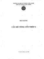
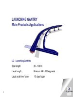
LG - Launching Gantries
Span length: 25 – 100+m
Usual Length: Minimum 500 - 800 segments
Usual cycle time / span 1-3 days / span
LAUNCHING GANTRY
Main Products Applications
2
FORMTRAVELLER
Main Products Applications
FT - Formtraveller
Span length: 40 – 300+ m
Usual cycle time: 2 x 1 segment / week
3
The formtraveller system was invented in 1970 and today it is
acclaimed for enhancing the cost-effectiveness of bridge projects world-
wide. We have continually improved the Formtraveller in collaboration
with major contractors. The system is lightweight, versatile and easy to
assemble and operate. Rolling forward on rails, the system can be
reset quickly and easily.
Where to use the Formtraveller
The Formtraveller is used for free cantilever construction of post-
tensioned boxgirder and cable-stayed concrete bridges. Engineered to
international standards, the system provides an exceptionally rigid
formwork, with a maximum deflection of less than 25 mm at full loading.
THE FORMTRAVELLER CONCEPT
4
The Formtraveller
The Standard Formtraveller is designed for a usual segment length of 5 m
and load capacities (concrete and formwork) varying from 100 tons to 600
tons. The steel weight depends on the cross-section of the bridge in
question, but will normally vary from about 25 tons to 110 tons
correspondingly. The Standard Formtraveller may be adapted to suite
almost any cross-section, and is easily adjustable during operation to
variations in segment length (up to 5 m), section height, web thickness,
and deck width. For segment lengths beyond 5 m and other conditions,
the Formtraveller will be tailor-made.
5
Lightweight:
The use of rectangular hollow sections in the main structural components and
recoverable high strength bars in all stays and ties reduces the total steel
weight to a minimum.
Flexible design:
The Formtraveller may be adapted to almost any cross-section and is easily
adjustable during operation to variations in segment length, box height, web
thickness, deck width and road alignment (gradient, curvature, super-
elevations).
Small deflections:
The vertical deflection at the front of the Formtraveller is less than 25 mm at
maximum load. Formwork beams are designed for a maximum deflection of
L/400 of their length.
Easy assembly:
One Formtraveller may be assembled in one week. Rolling
forward on rails, the reset time is short.
THE FORMTRAVELLER FEATURES
6
The Formtraveller:
Components
7
MAIN
RAILS
HYDRAULIC
CYLINDERS
The Formtraveller - Components
PULL DOWN
CYLINDERS
LAUNCHING
CYLINDERS
MAIN
CYLINDERS
8
FRONT & REAR
BOOGIES
MAIN
RAILS
HYDRAULIC
CYLINDERS
The Formtraveller - Components
9
FRONT & REAR
BOOGIES
MAIN
RAILS
HYDRAULIC
CYLINDERS
MAIN
FRAMEWORK
The Formtraveller - Components
10
FRONT & REAR
BOOGIES
MAIN
RAILS
HYDRAULIC
CYLINDERS
MAIN
FRAMEWORK
FRONT & REAR
FRAMEWORK
BOTTOM
FRAMEWORK
CROSS
ARMS
INTERNAL
FRAMEWORK
The Formtraveller - Components
11
FRONT & REAR
BOOGIES
MAIN
RAILS
HYDRAULIC
CYLINDERS
MAIN
FRAMEWORK
FRONT & REAR
FRAMEWORK
BOTTOM
FRAMEWORK
CROSS
ARMS
INTERNAL
FRAMEWORK
EXTERNAL
FORMWORK
BOTTOM
FORMWORK
INTERNAL
FORMWORK
The Formtraveller - Components
12
FRONT & REAR
BOOGIES
MAIN
RAILS
HYDRAULIC
CYLINDERS
MAIN
FRAMEWORK
FRONT & REAR
FRAMEWORK
BOTTOM
FRAMEWORK
CROSS
ARMS
END
FORMWORK
WORKING
PLATFORMS
The Formtraveller - Components
INTERNAL
FRAMEWORK
EXTERNAL
FORMWORK
BOTTOM
FORMWORK
INTERNAL
FORMWORK
13
The Formtraveller
14
The Formtraveller -
A normal working cycle may be as follows:
The Formtraveller, except for the internal formwork,
is launched into position for a new segment.
The external formwork is levelled and fixed.
Bottom slab and webs reinforced.
The internal formwork is pulled forward.
Top slab is reinforced.
Concreting of bottom slab and webs. The top slab
may be cast after a short intermission to allow
setting of the concrete in the webs, or it may be cast
the next day.
After sufficient concrete curing, post-tensioning takes
place.
Formwork is loosened, and the Formtraveller
launched forward to the next segment. In
most cases one cycle is carried out in
one week. There are examples
of 4-5 days cycles.
15
The Formtraveller: Alqueva II,Portugal
16
The Formtraveller: Arrade, Portugal
17
The Formtraveller: Alqueva, Portugal
18
The Formtraveller: Dyrøy bridge, Norway
19
The Formtraveller: Algés, Portugal
20
The Formtraveller: Loures, Portugal
21
The Formtraveller: Arrade, Portugal
22
The Formtraveller: Rio Minho, Portugal
23
The Formtraveller - Cross-Support for
installation on small Pierheads
When the pier head is too small to allow normal assembly of the Formtraveller, our
Cross-support solves the problem. It makes it possible to start free cantilevering from
pier heads as small as 3 m. The procedure is illustrated through the these 4 phases:
3 m
Phase 1:
Assembly at pierhead as small as 3 m
24
Phase 2:
Concreting of 1st segment on each side of the pier finished
The Formtraveller - Cross-Support for
installation on small Pierheads
When the pier head is too small to allow normal assembly of the Formtraveller, our
Cross-support solves the problem. It makes it possible to start free cantilevering from
pier heads as small as 3 m. The procedure is illustrated through the these 4 phases.
25
Phase 3:
Splitting of travellers
The Formtraveller - Cross-Support for
installation on small Pierheads
When the pier head is too small to allow normal assembly of the Formtraveller, our
Cross-support solves the problem. It makes it possible to start free cantilevering from
pier heads as small as 3 m. The procedure is illustrated through the these 4 phases.