Báo cáo hóa học: " Impacts of selected stimulation patterns on the perception threshold in electrocutaneous stimulation" doc
Bạn đang xem bản rút gọn của tài liệu. Xem và tải ngay bản đầy đủ của tài liệu tại đây (829.24 KB, 10 trang )
RESEARCH Open Access
Impacts of selected stimulation patterns on the
perception threshold in electrocutaneous
stimulation
Bo Geng
1*
, Ken Yoshida
1,2
, Winnie Jensen
1
Abstract
Background: Consistency is one of the most important concerns to convey stable artificially induced sensory
feedback. However, the constancy of perceived sensations cannot be guaranteed, as the artificially evoked
sensation is a function of the interaction of stimulation parameters. The hypothesis of this study is that the
selected stimulation parameters in multi-electrode cutaneous stimulation have significant impacts on the
perception threshold.
Methods: The investigated parameters included the stimulated location, the number of active electrodes, the
number of pulses, and the interleaved time between a pair of electrodes. Biphasic, rectangular pulses were applied
via five surface electrodes placed on the forearm of 12 healthy subjects.
Results: Our main findings were: 1) the perception thresholds at the five stimulated locations were significantly
different (p < 0.0001), 2) dual-channel simultaneous stimulation lowered the perception thresholds and led to
smaller variance in perception thresholds compared to single-channel stimulation, 3) the perception threshold was
inversely related to the number of pulses, and 4) the perception threshold increased with increasing interleaved
time when the interleaved time between two electrode s was below 500 μs.
Conclusions: To maintain a consistent perception threshold, our findings indicate that dual-channel simultaneous
stimulation with at least five pulses should be used, and that the interleaved time between two electrodes should
be longer than 500 μs. We believe that these findings have implications for design of reliable sensory feedback
codes.
Background
Human beings sense the external environment by exter-
oceptors and proprioceptors embedded throughout the
body, and the receptors are wired to the central nervous
system (CNS) via peripheral nerves. Injurie s to the ner-
vous system, for example transection of nerves following
the amputation of a limb, not only impair motor func-
tion but also result in abnormal sensory feedback or
neuropathic pain [1]. In those wit h upper limb amputa-
tion, proprioceptive, kinesthetic and tactile feedback
from the missing arm /hand is severe ly degraded. Use of
artificial arm/hand prostheses may restore some of the
motor function. Of equal importance, restoring some
sensory feedback would s ignificantly enhance the user
acceptance of prosthetic devices [2-5]. Partly or com-
plete rehabilitation of sensory function of upper limb
can significantly improve the quality of life for the
affected population.
Sensory feedback can be artificially induced using, e.g.,
mechanical indentation, intraneural electrical stimula-
tion or electrocutaneous stimulation [6-8]. Among these
methods, eletrocutaneous stimulation has been widely
used due to its non-invasiveness and capability of
producing a sensation whose frequency and intensity
can be reliably controlled [9,10]. A number of successful
applications of electrocutaneous stimulation in the
sensory feedback systems of artificial arm/hand were
reported [11-15].
Van Doren et al [2] stated that “ a successful sensory
feedback system must incorporate a sensory substitute
* Correspondence:
1
Center for Sensory-Motor Interaction, Department of Health Science and
Technology, Aalborg University, Fredrik Bajers vej 7 D, Aalborg Øst, Denmark
Full list of author information is available at the end of the article
Geng et al. Journal of NeuroEngineering and Rehabilitation 2011, 8:9
/>JNER
JOURNAL OF NEUROENGINEERING
AND REHABILITATION
© 2011 Geng et al; licensee BioMed Central Ltd. This is an Open Access article distributed under the terms of the Creative Commons
Attribution License (http://creative commons.org/licens es/by/2.0), which permits unrestricted use, distribution, and reproduction in
any medium, provided the original work is properly cited.
that is the right type and the right magnitude.” As such,
it is important to maintain a consistent strength of the
perceived sensation to gain users’ confidence in using
the arm/hand prostheses. However, consistent sensory
feedback cannot be guaranteed due to many factors, e.g.,
skin adaptation of sustained stimulation, impedance
changes caused by skin reaction. It is a non-linear rela-
tionship between stimulation parameters and output
sensory responses [9]. This non-linear relat ion constitu-
tes the main obstacle and challenge today to produc e a
reliable sensory feedback.
Sensory feedback coding is referred to as the rule by
which stimulus parameter modulation is mapped to sen-
sory modulation [16]. The input to this mapping may be
modulation of the stimulus amplitu de, pulse duration,
frequency etc. and the output is the evoked sensation.
The strength of the perceived sensation is dependent on
the perception threshold, which is varying with different
stimulation patterns.
People have investigated the effects of stimulation
parameters on the perception threshold in single-chan-
nel stimulation. For instance, an inverse relationship was
found between the perception threshold and the pulse
duration [17]. A study on excitation of sensory nerve
indicated that the sensory threshold was higher in the
legthanintheforearm[18].However,toourknowl-
edge, few work can be found in public literature on the
perception threshold i n dual-channel electrical stimula-
tion. Since dual-channel stimulation has proved to
increase the information transfer rate in sensory com-
munication by introducing additional parameters (e.g.,
the number of active electrodes, the timing between
electrodes) into the coding rule set [10], it is important
to further study the effect of different dual-channel sti-
mulation patterns on the perception threshold. The per-
ception thresholds on the forearm skin were examined
since stimulation of the peripheral nerve close to the
missing arm/hand likely produces more intuitive sensory
feedback to the amputee patients.
This study inv estiga ted the effect of selected stimula-
tion parameters on perception threshold, including the
stimulated location, the number of pulses, and the inter-
leaved time between a pair of electrodes. We also evalu-
ated the effect of the number of active electrodes by
comparing the perception thresholds in single-channel
stimulation with dual-channel stimulation. The hypoth-
esis to be tested in this study is that, the investigated sti-
mulation parameters have significant impacts on
perception threshold due to diff erent electrode config-
urations and different amount of injected charge contri-
buting to either skin physiological variability or ionic
micro-environment modification resulted from varied
electric field. In addition, the gender difference in per-
ception threshold was also examined.
Methods
Subjects
12 healthy human subjects (6 males and 6 females, age
22-39 years, mean 29.1 years) participated in the s tudy.
The number of subjects included was determined by the
power test performed along the experiments. When the
power of statistical comparisons all exceeded 0.8, our
recruitment of more subjects stopped. All subjects
signed an informed consent prior to the experiment.
The experimental p rotocol was in accordance with the
Declaration of Helsinki and approved by the Danish
Local Ethics Committee (approval no.: N-20090009).
The subjects had no visible skin diseases in the forearm
and no known history of neurological or psychological
disorders.
Experimental setup
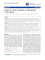
Figure 1 shows the schematic of the experimental setup.
The stimulation patterns were configured through the
stimulation control software residing in ‘Computer 1’.
The stimulus generator STG2008 (Multi Channel Sys-
tems, Reutlingen, Germany) generated single-channel or
dual-channel analog voltage output. The voltage-to-cur-
rent converters DS5s (Digitimer,Hertfordshire,UK)
then translated the voltage signal into isolated current
stimuli. The stimuli were delivered to one or two elec-
trodes selected by the two switches. The subject chose
‘ Yes ’ if he/she perceived the stimulation, otherwise
chose ‘No’ through a Graphical User Interface (GUI)
displayed in ‘Computer 2’. When the subject submitted
the answer, ‘Computer 1’ received an acknowledgement
signal and the next stimulation was delivered after 5
seconds. During the experiment, the stimulus informa-
tion was blind to the subjects.
Five Ambu Neuroline 700 solid gel electrodes (skin
contact size: 20 mm × 15 mm) were placed around the
left forearm 5 cm distant to the antecubital crease
(Figure 2). For brevity, the five electrodes (or channels)
are referred to as: E1, E2, E3, E4 and E5. The location
of the five electrodes was standardized among subjects
according to the following rules: 1) E1 was placed over
the median nerve, 2) E2 was placed laterally adjacent to
E1, 3) E3, E4, and E5 were equally spaced between E2
and E1. The common reference electrode was positioned
over the ulnar styloid process in the left forearm. The
median nerve was identified by applying electrical sti-
mulation with moderate intensity. The place where the
evoked sensation projected to the thenar eminence, the
thumb and/or the index and/or the middle finger was
then identified as the location of the median nerve. E1
and E2 were placed adjacently with the purpose to
examine the influence of the distance between electro-
des. The skin area identified for stimulation was pre-
pared with a water soaked cotton cloth to decrease the
Geng et al. Journal of NeuroEngineering and Rehabilitation 2011, 8:9
/>Page 2 of 10
impedance and thereby facilitate stimulus current
conduction.
A symmetric, biphasic, rectangular waveform was
applied since it had the lowest total charge among five
commonly used waveforms [18]. The pulse durations of
100 μs, 200 μsand500μs were first tested in a pilot
experiment. Pulse duration of 200 μs was finall y chosen
as it produced the least ‘ prickly’ sensation. The
frequencyof20Hzwasused,sinceitwasfoundthat
20 Hz might be the optimal frequency for sensory com-
munication as the maximum frequency discrimination
occurred near 20 Hz [19].
Stimulation application
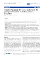
Four types of stimulation patterns were applie d (Figure
3). In Type 1, a single-pulse stimulus was applied to
individual electrodes. In Type 2, two single-pulse stimuli
were applied to a pair of electrodes simultaneously.
Seven out of ten possible electrode pair combinations
were measured, i.e., E1&E2, E1&E3, E1& E4, E1&E5,
E3&E4, E3&E5 and E4&E5. The remaining three, i.e.,
E2&E3, E2&E4 and E2&E5, were ignored, as we found
that the combinations with E2 resulted in similar per-
ception thresho lds to those co mbinations wi th E1
(results not shown). In Type 3, two multi-pulse stimuli
(n = 2, 5, 10, or 20) were applied to a pair of electrodes
simultaneously. Considering the amount of time needed
to measure all combinations, only three pairs were mea-
sured in the Type 3 stimulation, i.e., E1&E2, E1&E4,
and E3&E5. These three were selected because they
include all the five electrode locations and varying inter-
electrode distances. In the Type 4, two single-pulse sti-
muli were applied to two electrodes with an interleaved
time (t = 0.05 ms, 0.1 ms, 0.2 ms, 0.5 ms, 1 ms, 5 ms,
10 ms, or 50 ms). The same three electrode pair combi-
nations were measured for the Type 4 stimulation. As
such, the perception thresholds of totally 48 different
stimulation parameter combinations were measured for
each subject.
Perception threshold measurement
The perception threshold was defined as the current
amplitude that a subject could just barely detect. The
amplitude was measured on the activation side (i.e.,
D
S
5
STG2008
Voltage
Current
Current
Voltage
E1
E2
E3
E4
E5
Subject
Switch 2
Switch 1
Computer 2
Computer 1
(Stimulation control)
Figure 1 E xperimental setup for the perception thres hold measurement. The experimental procedure was exec uted on a computerized
platform. The stimulation profiles were configured through the stimulation control software residing in ‘Computer 1 ’. The STG2008 generated
analog voltage output, and then the DS5s translated the voltage signal into current signal. The stimuli were delivered to one or two electrodes
selected by the ‘Switches’. The subject answered whether or not they perceived a stimulus through a Graphical User Interface displayed in
‘Computer 2’.
E1
E
2
E
3
E4
E5
Figure 2 Schematic of the cross-section view of the electrode
placement. Five electrodes were placed around the forearm (view
from the distal side). The right side (E3) corresponds to the radial
side. The upper side corresponds to the ventral side (E1 and E2).
Geng et al. Journal of NeuroEngineering and Rehabilitation 2011, 8:9
/>Page 3 of 10
negative phase) of the biphasic pulse. The measurement
of the perception threshold proceeded as illustrated in
Figure 4. First, the perception threshold was roughly
estimated by applying a series of ascending-amplitude
stimuli with a step size 0.2 mA. The average of the
amplitude of the last ‘ not-perceived’ and the first ‘per-
ceived’ stimulus was then identified as t he approximate
threshold. Then, seven stimuli were chosen, with ampli-
tudes in a range encompassing the approximate thresh-
old just identified, but with a smaller step size of 0.1
mA. Afterwards, three repetitions of the seven ampli-
tudes was mixed and presented to the subject in a
pseudo-random order (i.e., totally 21 stimuli). After each
stimulus presentation, the subject reported whether or
not the stimulus was perceived. Finally, the frequencies
of ‘perceived’ and ‘not-perceived’ reports were calculated
for each of the seven intensities. Due to the variability
in the biological sensor systems and psychological
fluctuation, the plot of frequency against intensity is
typically not all-or-none curve [20]. In general, a lower
amplitude was occasionally perceived and a higher
amplitude was more often perceived. It was assumed
that within the vicinity of the perception threshold, the
frequency of ‘ perceived’ responses and the stimulus
intensity are linearly correlated [21]. Thus, the percep-
tion threshold was determined by predicting the inten-
sity that would b e detected in 50 percent of the trials
(i.e., 1.5 times). Robust linear regression was used to
implement the prediction.
Data analysis
The effects of the investigated stimulation parameters
on the perception threshold were statistically evaluated.
Based on the observation of the Q-Q plots of the four
individual stimulation types, the perception threshold
data wer e assumed to follow a normal distributi on. The
independent variables were ‘stimulated location’, ‘chan-
nel combination’, ‘the number of pulses’ and ‘interleaved
time’. The dependent variable was ‘perception threshold’
in all comparisons. A one-way, repeated analysis of var-
iance (ANOVA) was performed and the F-test was used
to test if there was a significant effect of an independent
variable. The significance level was chosen to be 0.05.
When a significant difference was found, individual
Type 1:
S
ingle-channel, single-pulse
stimulation.
Type 3: Two-channel, multi-pulse (n = 2,5,10, or 20)
stimulation.(T = 1/f = 0.05 s)
T
ype 2: Two-channel, single-pulse,
simultaneous stimulation.
Type 4: Two-channel, single-pulse, interleaved stimulatio
n
(t=0.05ms,0.1ms,0.2ms,0.5ms,1ms,5ms,10ms, or 50ms)
Interleaved time
Amplitude
Duration
t
Channel A:
Channel B:
Channel A:
Channel B:
T
12 n
T
Channel A:
Channel B:
Figure 3 Illustration of the four types of stimulation patterns. Left-Top (Type 1): Single-channel, single-pulse stimulation. Left-bottom
(Type 2): Dual-channel, single-pulse simultaneous stimulation. Right-Top (Type 3): Dual-channel, multi-pulse, simultaneous stimulation with n
pulses. Right-Bottom (Type 4): Dual-channel, single-pulse stimulation with interleaved time t.
Geng et al. Journal of NeuroEngineering and Rehabilitation 2011, 8:9
/>Page 4 of 10
pairs of conditions were further compared using multi-
ple pairwise comparisons with Bonfe rroni adjustment.
The relationship between the perception threshold and
the number of pulses or the interleaved time was further
evaluated by curve fitting.
Results
Effect of the stimulated location on the perception
threshold
The lowest perception threshold (PT) was found at E1
and E2, whereas the highest PT was found at E4 (dorsal
side) (see figure 5A). The PTs at E3 and E5 were at the
middle level. As such, it appears that the closer the elec-
trode was placed to the median nerve, the lower the PT.
The ANOVA result indicated that the stimulated loca-
tion had a significant effect on the PT (F (4, 55) =
12.03, p<0.0001, test power = 0.91). Pairwise compari-
sons were then performed. Table 1 lists the results o f
the multiple comparisons. The PT at E4 had a signifi-
cant difference from all other four electrodes.
Effect of the number of active electrodes: single-channel
vs. dual-channel stimulation
The PTs in dual-channel stimulation were observed less
varying than in single-channel stimulation (see figure
5B). The effect of the number of active electrodes was
evaluated by comparing the PT in dual-channel stimula-
tion with the PT in stimulation of either of the two
channels. We found that, for pairs of electrodes showing
no significant difference in Table 1 (i.e., E1 and E2, E1
and E5, E3 and E5), simultaneous stimulation of the two
electrodes reduced the PT. This result verifies that
incorporating additional electrodes increased the band-
width of sensory information transfer.
To examine the effect of the distance between electro-
des in dual-channel stimulation, we compared the PT at
E1 with the PTs at E1 combined with the other four
electrodes in dividually. Moreover, the PT at E3 was
compared with the PT at E3 combined with E4 and E5,
respectively. The results of the statistical comparisons
are listed in Table 2.
Intensity
(mA)
0.8
0.9
1
1.1
1.2
1.3
1.4
Frequency
of
perceived stimuli
0
1
1
2
2
3
3
Intensity
(mA)
Response
N
0.6
N
0.8
N
1
N
1.2
Y
1.4
Y
1.6
Y
Y
0,8
0,9
1
1,1
1,2
1,3
1,4
Step 1: Estimate the threshold.
Step 2: Choose seven stimulus
intensities encompassing the
estimated threshold and generate
three repetitions f or each intensity.
Step 4: Predict the current intensity that can be detected in 50% of
trials, which is determined as the perception threshold.
S
tep 3:
C
alculate the
f
requency o
f
perceived repsonses
f
or each intensity
.
0.7 0.8 0.9 1 1.1 1.2 1.3 1.4
0
1
2
3
4
stimulus amp.
Freq. of perceived stimuli
Data
Robust Regression
Threshold: 1.06
0,8
0,9
1
1,1
1,2
1,3
1,4
0,8
0,9
1
1,1
1,2
1,3
1,4
Intensit
y
Frequency
Figure 4 Measureme nt of the perception threshold with an example data from a subject. Step 1: The perception threshold was roughly
estimated to be 1.1 mA, since 1.0 mA was the intensity last perceived and 1.2 mA was the one first perceived. Step 2: Seven intensities were
chosen in the range of 0.8~1.4 mA. Three repetitions produced 21 stimuli. Step 3: The frequency of ‘perceived’ responses were calculated for
each of the seven intensities. Step 4: The perception threshold was determined to be 1.06 mA by predicting the intensity that would be
detected in 50% of trials (i.e., 1.5 times).
Geng et al. Journal of NeuroEngineering and Rehabilitation 2011, 8:9
/>Page 5 of 10
It can be seen that, compared to single-channel stimu-
lation at E1, incorporation of a second channel s ignifi-
cantly reduced the PT, irrespective of the distance to
E1. The extent of the decrease depended on the dis-
tance. The closer the second electrode was placed to E1,
the more the PT was reduced. The extent of the PT
reduction can be reflect ed in the 95% confidence interval
of the mean difference. A larger mean difference suggests
a larger PT decrease. The mean difference of the PT at
E1 and at E1&E2 was the highest, since E2 was placed
closest to E1. Similarly, the PT mean difference between
E3 and E3&E4 was larger than between E3 and E3&E5
since E3 was further away from E5 than E4.
A
B
C
D
Figure 5 Mean and standard deviations of the PTs measured from all subjects. A. PTs in the single-channel , single-pulse stimulation
(Type 1); B. PTs in the dual-channel, single-pulse simultaneous stimulation (Type 2); C. PTs in the dual-channel, multi-pulse, simultaneous
stimulation (Type 3); D. PTs in the dual-channel, single-pulse, interleaved stimulation (Type 4). Note that the three electrode combinations in
C and D are indicated by three different colors in the inset schematic of electrode placement.
Table 1 Pairwise comparisons of the mean PTs among
five electrode sites
Electrode pair Significant
difference?
P-value 95% CI of mean
difference (mA)
(E1, E2) No 1.000 [-0.19, 0.21]
(E1, E3) Yes 0.028 [-0.74, -0.03]
(E1, E4) Yes 0.002 [-1.88, -0.42]
(E1, E5) No 0.267 [-1.00, 0.16]
(E2, E3) Yes 0.038 [-0.78, -0.02]
(E2, E4) Yes 0.001 [-1.84, -0.49]
(E2, E5) No 0.128 [-0.95, 0.08]
(E3, E4) Yes 0.017 [-1.41, -0.12]
(E3, E5) No 1.000 [-0.62, 0.54]
(E4, E5) Yes 0.026 [0.07, 1.38]
Table 2 PT comparisons of single-channel and dual-
channel stimulation
Comparison Significant
difference?
P-value 95% CI of mean
difference (mA)
Test
Power
E1 vs. E1&E2 Yes 7E-7 [0.37, 0.59] 1.00
E1 vs. E1&E3 Yes 0.012 [0.01, 0.43] 0.80
E1 vs. E1&E4 Yes 0.013 [0.05, 0.36] 0.77
E1 vs. E1&E5 Yes 0.011 [0.08, 0.45] 0.82
E3 vs. E3&E4 Yes 0.004 [0.21, 0.78] 0.94
E3 vs. E3&E5 Yes 0.008 [0.16, 0.77] 0.86
Geng et al. Journal of NeuroEngineering and Rehabilitation 2011, 8:9
/>Page 6 of 10
Effect of the pulse number on the perception threshold
Figure 5C shows the PTs measured in the dual-channel,
simultaneous stimulation with five varied pulse num-
bers. In the bar plot, a slight decline of the PT with the
increasing pulse number can be observed. The ANOVA
analysis indicates that there was a significant effect
of the pulse number on the PT (E1&E2: F (4, 55) = 5.96,
p < 0.01, test power = 0.87; E1&E4: F (4, 55) = 18.98,
p < 0.0001, test power = 1.00; E3&E5: F (4, 55) = 24.26,
p < 0.0001, test power = 1.00).
Curve fitting was further used to examine the effect of
pulse number on the PT (Figure 6). An inverse relation-
ship between the PT and the pulse number n: PT = a+
b/n was found in all the three electrode combinations.
The results indicate a significa nt effect of pulse number
on the PT. Note that, the data of each subject was nor-
malized to the PT measured with this subject when the
pulse number was one, in order to eliminate the effects
from other factors.
Effect of the interleaved time between a pair of
electrodes
An increase of the PT with increasing interleaved time
between a pair of electrodes was observed in all the
three electrode pair combinations (see figure 5D). Curve
fitting was used to esti mate the relationship between the
PT and the interleaved time (see Figure 7). Likewise,
the data colle cted from each subject were normalized by
the PT measured with this subject when the interleaved
time was 0. A sigmoid relationship was found between
the PT and the interleaved time t:log(PT)=c + d/t.
The results indicate a significant effect of the interleaved
time on the PT.
C
A
B
Figure 6 Relationship between the normalized PT and the
number of pulses. A. E1&E2. B. E1&E4. C. E3&E5. An inverse
relationship between the PT and the pulse number n: PT = a + b/n
was found in all the three electrode combinations. The highlighted
electrodes in the inset schematic indicate the location of stimulated
electrodes corresponding to the figure.
A
B
C
Figure 7 Relationship between the normalized PTs and the
interleaved time between two channels. A. E1&E2. B. E1&E4. C.
E3&E5. A sigmoid relationship was estimated between the PT and
the interleaved time t: log (PT)=c + d/t. The highlighted electrodes
in the inset schematic indicate the location of active electrodes
corresponding to the figure.
Geng et al. Journal of NeuroEngineering and Rehabilitation 2011, 8:9
/>Page 7 of 10
The PT increased with increasing interleaved time and
reached a plateau approximately at the point of 500 μs.
The ANOVA analysis indicated a significant difference
among the PTs below 500 μs(p < 0.01, p < 0.05, and
p < 0.05 in E1&E2, E1&E4 and E3&E5, respectively),
while no significant difference was found above 500 μs.
Gender difference
We also investigated the effect of gender on the PT.
Figur e 8 shows the mean and st andard deviations of the
PT in single-channel, single-pulse stimul ation. The
interesting finding was that, at all five locations, the
female subjects exhibited lower PTs than the male sub-
jects. The mean differences between the male and
female subjects are 0.18 mA, 0.22 mA, 0.44 mA, 0.88
mA, and 0.61 mA, respectively (from E1 to E5).
Discussions
Perception of an external stimulus essentially results
from the activation of the afferent units present in the
skin. The modalities of evoked sensations are deter-
mined by the types of activated sensory receptors. In
this study, the subjects reported the sensations of touch,
light pressure and tingling. Thus, we believe that the
activated receptors were likely the hair follicles, Ruffini,
or free nerve e ndings, and the corresponding nerve
fibers activated were the Ab or Aδ [22]. When the dual-
channel stimulation was applied to E1 and E2, the sub-
jects could not discriminate the two stimulation sites,
which could be explained by the fact that E1 and E2
were located within one receptive field. In the case of
the dual-channel stimulation of other electrode pairs,
most subjects reported to perceive the stimulation at the
channel with lower PT.
The significantly different PTs measured at the five
electrode locations suggest that the stimulus amplitude
adequate to elicit a sensation varies across the skin.
We speculate that the skin impedance may be one of
the sources accounting for the PT variations (the skin
impedance was not measured in the current study).
Humanskintissuecanbemodeledbyanequivalent
circuit using multiple resistors and capacitors (see e.g.,
[23-25]). Skin thickness has an influence on the dis-
tance between the stimulus source and the nerve end-
ings in the skin. A larger distance between the current
source and the activated nerve endings indicates a
higher coupling impedance, which correspondingly
results in a higher propagation loss. A higher current
amplitude is thus needed to activate the afferent recep-
tor or fibers, and consequently it results in a higher
PT. A previous study based on ultrasonic imaging
techniques demonstrated that the s kin is thicker on
the dorsal than volar forearm [26]. Even within the
skin area under a surface gel-type electrode, the elec-
trical current density is distributed unevenly due to
uneven skin resistivity [27]. The result that E1 and E2
(ventral side) had lower PTs while E4 (dorsal side) had
a higher PT, assists to strengthen our speculation that
lower skin impedance led to lower PT. Another possi-
ble source of the PT variability might be the variations
in the density of nerve endings. It can be partly sup-
ported by previous studies on tactile afferent units dis-
tributed in the forearm, in which the receptive field
was found to be varied widely in size [28,29].
No significant difference in the PT was found between
E1 and E2, likely because E1 and E2 are closely located
and the afferent fibers innervating the skins under E1
and E2 overlap spatially, causing the same set of sensory
fibers were activated.
ThereducedPTsbysimultaneous stimulation at
E1&E2 may be explained by spatial summation of the
electric fields. More electric charges were injected in
dual-channel stimulation than single-channel stimula-
tion, resulting in lower current amplitude required to
activate the nerve endings. PT reduction was found also
in dual-channel simultaneous stimulat ion when the two
electrodes were located not so close (from 10 cm to
20 cm depending on the forearm size), i.e., E1&E4 or
E3& E5. This might be caused by the charg e summation
occurring centrally, even if distinct sets of nerve fibers
were activated peripherally. Another possible explana-
tion is that the receptive field sizes for some types of
afferents are fairly large. Although E4 was located farth-
est away from E1 , the groups of cutaneous nerve fibers
under E1 and E4 electrodes may still overlap. This spec-
ulation may be supported by the fact that the receptive
fields of myelinated afferents in the forearm could be up
to 210 mm
2
[29].
E1 E2 E
3
E4 E
5
0
0.5
1
1.5
2
2.5
3
3.5
4
PT(mA)
Female
Male
Figure 8 Bar plot of the perception thresholds in the female
and male subjects. The mean differences between the male and
female subjects are 0.18 mA, 0.22 mA, 0.44 mA, 0.88 mA, and 0.61
mA, respectively (E1 to E5).
Geng et al. Journal of NeuroEngineering and Rehabilitation 2011, 8:9
/>Page 8 of 10
In the dual-channel interleaved stimulation, the inter-
leaved time shorter than 200 μs(i.e.,pulseduration)
could lead to a temporal overlap of two pulses and con-
sequently a temporal summation of electric fields. The
summation caused a lower current for the threshold
activation of nerve fibers. When the interleaved time
increased above the pulse duration (i.e., 200 μs), no
more temporal overlap occurred. However, the transi-
tion point did not occur at 200 μs. We consider that,
immediately after the pulse overlap period there likely
was a ‘ RC recovery time interval’ ,duringwhichthe
membrane still contained the charge of the first stimu-
lus, causing that the second stimulus raised the mem-
brane potential above excitation threshold [30].
The PT barely changed when the interleaved time is
longer than 500 μs. This imply that the PT may be
more stable when the time separation between two elec-
trodes longer than 500 μs. Similarly, a sat uration effect
was observed when the pulse number was larger than
five. This may suggest that a stimulus with at least five
pulses is capable of producing more consistent strength
of perceived sensation.
This study mainly focused on the effects of different
stimulation patterns on the PT within subjects. How-
ever, the variation between subjects should not be
ignored. One source of the variation between subjects
might be resulted from the variability of the body f at
percent age from subject to subject (the body fat percen-
tage was not measured in the current study). The body
fat percentage is closely associated with the tissue
volume conduc tor, which directly impacts the nerve
fiber recruitment. It is well established that women gen-
erally have a higher percentage of body fat than men.
Since the PTs in the female subject s were shown to be
lower than the male subjects, it may imply that the PT
was interrelated to the body fat percentage. It sho uld be
noted that the conclusion that females have lower PT
than males is speculative due to the small sample size.
Yet the observatio n is in accordance with the finding in
[31].
The method of constant stimuli was used to measure
the PT. In the classical method of constant stimuli, a set
of stimulus intensities (usually from 5 to 9) encompass-
ing the actual threshold are chosen and then presented
multiple times (usually not less than 20 times) in a
pseudo-random order, with each occurring equally fre-
quent. Once the percentage of ‘perceived’ and ‘not per-
ceived’ responses to each intensity calculated and
plotted against stimulus intensity, the PT i s determined
by linear interpolation of the stimulus intensity per-
ceived in 50% of present times. The method of constant
sti muli is generally considered to provide the most reli-
able estimate of the PT ( see e.g. [21]) , as a random pre-
sentation of stimuli can efficiently eliminate the possible
bias from the subject’s anticipation. However, its main
drawback is that many times of presentations of each
value and tracking of the subject’s response is consider-
ably time-consuming, which easily distract the subject’s
attention. To limit the time consumption and mean-
while maintain m easurement accuracy, we reduced the
number of presentations of each intensity and compen-
sated the possible accuracy loss by introducing a
‘roughly-estimate’ procedure. That is, a series of intensi-
ties with a bigger step size was used to roughly estimate
the threshold, and then around the threshold just esti-
mated, a set of intensities with a smaller step size w as
presented to the subject multiple times. As such, the
procedure optimized the intensity set by adapting the
stimuli according to the subject’s responses.
Choosing the step size of the stimulus amplitudes is
critical since only amplitudes near the threshold can
provide useful information. Too big step sizes may over-
estimatethethresholdrangeinthatsomeoftheampli-
tudes will be too far away from the actual threshold,
causing inefficiency. Too small step sizes possibly under-
estimate the threshold range, leading to biased measure-
ment o f the threshold. The optimal amplitude set
should be just across the region of sensory fluctuation.
In our pilot experiment, five different steps sizes (0.02
mA, 0.05 mA, 0.1 mA, 0.15 mA, 0.2 mA) were tested in
single-channel, single-pulse stimulation with one subject.
With each step size, the PT was measured several times
following the procedure described in the section of per-
ception threshold measurement . It was observed that, in
the case of 0.15 mA and 0.2 mA most stimulus intensi-
ties were either ‘perceived’ or ‘not perceived’ in all three
repetitions, which provided limited information for the
PT estimation. In the case of 0.02 mA and 0.05 mA,
inconsistent PTs were obtained in the measurements.
Therefore, 0.1 mA was chosen to be the step size.
This study revealed the influence of the investigated
electrical stimulation parameters on the PT on the fore-
arm skin. The results provide insight into the use of
electrocutaneous stimulation to induce magnitude-stable
sensory feedback in advanced upper limb or hand pros-
the ses. Also, the results give implication for selection of
appropriate stimulation parameters for sensory discrimi-
nation training program, which can be used to reduce
PLP or other chronic limb pain [32,33].
Conclusions
Within the study on a limited set of stimulation para-
meters in single-channel and dual-channel stimulation,
we conclude that incorporation of a second stimulating
electrode reduced the perception threshold. In dual-
channel simultaneous stimulation, there is an inverse
relationship between the perception threshold and the
number of pulses. And the perception threshold is
Geng et al. Journal of NeuroEngineering and Rehabilitation 2011, 8:9
/>Page 9 of 10
positively related to the time separation in the inter-
leaved stimulation when the interleaved time was
shorter than 500 μs. Based on the findings, we propos e
that dual-channel stimulation with pulse number larger
than five, as well as the time separation between two sti-
muli longer than 500 μs in interleaved stimulation can
be used to achieve reliable perception threshold. We
also suggest applying the stimulation on the ventral side
of the forearm to induce sensory feedback because it
has significantly lower PT than the dorsal side. The
findings may help develop reliable sensory feedback
codes and provide an insight into understanding the
neurophysiological substrate of electrocutaneous
stimulation.
Acknowledgements
This study was funded by the EU TIME project (CP-FP-INFSO 224012/TIME).
Author details
1
Center for Sensory-Motor Interaction, Department of Health Science and
Technology, Aalborg University, Fredrik Bajers vej 7 D, Aalborg Øst, Denmark.
2
Biomedical Engineering Department, Indiana University-Purdue University
Indianapolis, 723 W. Michigan St, Indianapolis, USA.
Authors’ contributions
BG, WJ and KY designed the experimental protocol. BG performed the
experiment, conducted data collection and analysis. KY, WJ and BG outlined
the fundamental concepts of the scientific research, and contributed to the
preparation of the manuscript. All authors read and approved the final
manuscript.
Competing interests
The authors declare that they have no competing interests.
Received: 23 June 2010 Accepted: 9 February 2011
Published: 9 February 2011
References
1. Flor H: Phantom-limb pain: Characteristics, causes, and treatment. Lancet
Neurol 2002, 1:182-189.
2. Van Doren CL, Riso RR, Milchus K: Sensory feedback for enhancing upper
extremity neuromuscular prostheses. J Neuro Rehab 1991, 5:63-74.
3. Schmidt H: The importance of information feedback in prostheses for
the upper limbs. Prosthet and Orthot Int 1977, 1:21-24.
4. Prior RE, Lyman J, Case PA, Scott CM: Supplemental sensory feedback for
the VA/NU myoelectric hand: background and feasibility. Bull Prosth Res
1976, 10:170-191.
5. Atkins DJ, Heard DCY, Donovan WH: Epidemiologic overview of
individuals with upper-limb loss and their reported research priorities.
J Prosthet Orthot 1996, 8:2-11.
6. Dhillon GS, Horch KW: Direct neural Sensory feedback and control of a
prosthetic arm. IEEE Trans Neural Syst Rehabil Eng 2005, 13:468-472.
7. Kaczmarek KA, Webster JG, Bach-y-Rita P, Tompkins WJ: Electrotactile and
vibrotactile displays for sensory substitution systems. IEEE Trans Biomed
Eng 1991, 38:1-16.
8. Antfolk C, Balkenius C, Rosen B, Lundborg G, Sebelius F: Smarthand tactile
display: A new concept for providing sensory feedback in hand
prostheses. J Plast Surg Hand Surg 2010, 44:50-53.
9. Pfeiffer EA: Electrical stimulation of sensory nerves with skin electrodes
for research, diagnosis, communication and behavioral conditioning: A
survey. Med Biol Eng 1968, 6:637-651.
10. Szeto AYJ, Saunders FA: Electrocutaneous stimulation for sensory
communication in rehabilitation engineering. IEEE trans Biomed Eng 1982,
29:300-308.
11. Beeker ThW, During J, Den Hertog A: Artificial touch in a hand prosthesis.
Med biol Eng 1967, 5:47-49.
12. Patterson PE, Katz JA: Design and evaluation of a sensory feedback
system that provides grasping pressure in a myoelectric hand. J Rehabil
Res Dev 1992, 29:1-8.
13. Shannon GF: A myoelectrically-controlled prostheses with sensory
feedback. Med Biol Eng Comput 1979, 17:73-80.
14. Scott RN, Brittain RH, Caldwell RR, Cameron AB, Dunfield VA: Sensory-
feedback system compatible with myoelectric control. Med Biol Eng
Comput 1980, 18:65-69.
15. Kim G, Asakura Y, Okuno R, Akazawa K:
Tactiles substitution system for
transmitting a few words to a prosthetic hand user. Proceedings of
Annual international Conference of the IEEE Engineering in Medicine and
Biology: 1-4 Sept 2005; Shanghai 2005, 7:6908-6911.
16. Szeto AYJ: Electrocutaneous code pairs for artificial sensory
communication systems. Ann Biomed Eng 1982, 10:175-192.
17. Sang CN, Max MB, Gracely RH: Stability and reliability of detection
thresholds for human A-Beta and A-Delta sensory afferents determined
by cutaneous electrical stimulation. J Pain Symptom Manag 2003,
25:64-73.
18. Kantor G, Alon G, Ho HS: The effects of selected stimulus waveform on
pulse and phase characteristics at sensory and motor thresholds. Phys
Ther 1994, 74:951-962.
19. Szeto AYJ, Lyman J, Prior RE: Electrocutaneous pulse rate and pulse width
psychometric function for sensory communications. Human Factors 1979,
21:241-249.
20. Gescheider GA: Classical psychophysical theory. Psychophysics: the
fundamentals. 3 edition. Mahwah, NJ: Lawrence Erlbaum Associates; 1997.
21. Ehrenstein WH, Ehrenstein A: Psychophysical methods. In Modern
techniques in neuroscience research. Edited by: Windhorst U, Johansson H.
Berlin: Springer; 1999:1211-1241.
22. Warren S, Capra NF, Yezierski : In Fundamental Neuroscience for Basic and
Clinical Applications. Edited by: Haines DE. Philadelphia: Churchill
Livingstone Elsevier; 2006.
23. Edelberg R: Electrical properties of the skin. In Biophysical Properties of
Skin. Edited by: Elden HR. New York: Wiley-Interscience; 1971.
24. Yamamoto T, Yamamoto Y: Non-linear electrical properties of skin in the
low frequency range. Med Biol Eng Comput 1981, 19:302-310.
25. Kuhn A: Modeling transcutaneous electrical stimulation. PhD thesis. ETH
No. 17948 2008.
26. De Rigal J, Escoffier C, Querleux B, Faivre B, Agache P, Leveque JL:
Assessment of aging of the human skin by in vivo ultrasonic imaging.
J Invest Dermatol 1989, 93:621-625.
27. Patriciu A, Yoshida K, Struijk JJ, DeMonte TP, Joy MLG, Stoødkilde-
Jørgensen H: Current density imaging and electrically induced skin burns
under surface electrodes. IEEE trans Biomed Eng 2005, 52:2024-2031.
28. Wessberg J, Olausson H, Fernstrom KW, Vallbo AB: Receptive field
properties of unmyelinated tactile afferents in the human skin.
J Neurophysiol 2003, 89:1567-1575.
29. Vallbo AB, Olausson H, Wessberg J, Kakuda N: Receptive field
characteristics of tactile units with myelinated afferents in hairy skin of
human subjects. J Physiology 1995, 483:783-795.
30. Rutten WLC, Van Wier HJ, Put JHM: Sensitivity and selectivity of
intraneural stimulation using a silicon electrode array. IEEE Trans Biomed
Eng 1991, 38:192-198.
31. Maffiuletti NA, Herrero AJ, Jubeau M, Impellizzeri FM, Bizzini M: Differences
in electrical stimulation thresholds between men and women. Ann
Neurol 2008, 63:507-512.
32. Flor H, Dencke C, Schaefer M, Grüsser S: Effect of sensory discrimination
training on cortical reorganisation and phantom limb pain. Lancet 2001,
357:1763-1764.
33. Moseley GL, Zalucki NM, Wiech K: Tactile discrimination, but not tactile
stimulation alone, reduces chronic limb pain. Pain 2008, 137:600-608.
doi:10.1186/1743-0003-8-9
Cite this article as: Geng et al.: Impacts of selected stimulation patterns
on the perception threshold in electr ocutaneous stimulation. Journal of
NeuroEngineering and Rehabilitation 2011 8:9.
Geng et al. Journal of NeuroEngineering and Rehabilitation 2011, 8:9
/>Page 10 of 10