Báo cáo hóa học: " Exploring the bases for a mixed reality stroke rehabilitation system, Part II: Design of Interactive Feedback for upper limb rehabilitation" doc
Bạn đang xem bản rút gọn của tài liệu. Xem và tải ngay bản đầy đủ của tài liệu tại đây (3.46 MB, 21 trang )
METH O D O LOG Y Open Access
Exploring the bases for a mixed reality stroke
rehabilitation system, Part II: Design of Interactive
Feedback for upper limb rehabilitation
Nicole Lehrer
1*
, Yinpeng Chen
1
, Margaret Duff
1,2
, Steven L Wolf
1,3
and Thanassis Rikakis
1
Abstract
Background: Few existing interactive rehabilitation systems can effectively communicate multiple aspects of
movement performance simultaneously, in a manner that appropriately adapts across various training scenarios. In
order to address the need for such systems within strok e rehabilitation training, a unified approach for designing
interactive systems for upper limb rehabilitation of stroke survivors has been developed and applied for the
implementation of an Adaptive Mixed Reality Rehabilitation (AMRR) System.
Results: The AMRR system provides computational evaluation and multimedia feedback for the upper limb
rehabilitation of stroke survivors. A participant’s movements are tracked by motion capture technology and
evaluated by computational means. The resulting data are used to generate interactive media-based feedback that
communicates to the participant detailed, intuitive evaluations of his performance. This article describes how the
AMRR system’s interactive feedback is designed to address specific movement challenges faced by stroke survivors.
Multimedia examples are provided to illustrate each feedback component. Supportive da ta are provided for three
participants of varying impairment levels to demonstrate the system’s ability to train both targeted and integrated
aspects of movement.
Conclusions: The AMRR system supports training of multiple movement aspects together or in isolation, within
adaptable sequences, through cohesive feedback that is based on formalized compositional design principles.
From preliminary analysis of the data, we infer that the system’s ability to train multiple foci together or in isolation
in adaptable sequences, utilizing appropriately designed feedback, can lead to functional improvement. The
evaluation and feedback frameworks established within the AMRR system will be applied to the development of a
novel home-based system to provide an engaging yet low-cost extension of training for longer periods of time.
Background
Sensorimotor rehabilitatio n can be effective in reducing
motor i mpairment when engaging the user in repetitive
task training [1]. Virtual realities (exclusively digital) and
mixed realities (combining digital and physical elements)
can provide augmented feedback on movement perfor-
mance for sensorimotor rehabilitation [2-8]. Several
types of augmented feedback environments may be used
in conjunction with task oriented training. Some virtual
reality environments for upper limb rehabilitation have
been categorized as “ game-like” because the user
accomplishes tasks in the context of a game, while some
are described as “teacher-animation”,inwhichtheuser
is directly guided throughout his m ovement [9]. Among
the teacher-animation environments for upper limb
rehabilitation, several provide a three-dimensional repre-
sentation of a hand or arm controlled by t he user ,
which relate feedback to action by directly representing
the user’s experience in physical reality. Some applica-
tions, in contrast, use simple abstract environments (e.
g., mapping hand movement to moving a cursor) to
avoid providing potentially extraneous, overwhelming or
confusing information. However, because functional
tasks require knowledge and coordination of several
parameters by the mover, an excessive reduction in
complexity of action-related information may impede
* Correspondence:
1
School of Arts, Media and Engineering, Arizona State University, Tempe,
USA
Full list of author information is available at the end of the article
Lehrer et al . Journal of NeuroEngineering and Rehabilitation 2011, 8:54
/>JNER
JOURNAL OF NEUROENGINEERING
AND REHABILITATION
© 2011 Lehrer et al; licensee BioMed Central Ltd. This is an Open Access article distributed under the terms of the Creative Commons
Attribution License (http://cre ativecom mons.org/licenses/by/2.0), which permits unrestrict ed use, distribution, and reproduction in
any medium, provided the original work is properly cited.
functional rehabilitation [10,11]. Augmented feedback
for rehabilitation can best leverage motor learning prin-
ciples if it allows the participant to focus on individual
aspects of movement in the context of other key aspects
of the trained movement. Therefore feedback should
promote understanding of the relationships among mul-
tiple movement components.
Feedback used for rehabilitation training must also be
adaptable in design, allowing for c hanges in training
intensity and focus. Yet few existing augmented reality
rehabilitation environments effectiv ely communicate
multiple aspects of movement performance simulta-
neously, or furthermore, do so in a manner that is adap-
table and generalizes across multiple training scenarios.
In our companion pa per, Lehrer et al pre sent a methodol-
ogy f or developing interactive systems for strok e rehabilita-
tion that allow for adaptive, integrated training of multiple
movement aspects [12]. While the methodology may be
generalized to different types of movement training within
stroke rehabilitation, this paper applies the methodology to
interactive reach and grasp training as exemplifi ed in the
Adaptive Mixed Reality Rehabilitation (AMRR) System.
We now provide an overview of the AMRR system and
participant experience, followed by a more detailed discus-
sion of the applied design methodology within the system’s
implementation. An action representation for reach and
grasp training is presented with accompanying methods
for quantifying the representation’s kinematic features,
which allow for measurable evaluation of performance and
generation of media-based feedback. Descriptions of how
the AMRR feedback addresses specific movement chal-
lenges are then provided, with corresponding multimedia
examples. An overview of the system’s adaptation of the
feedback and training environments demonstrates how
AMRR training can be customized for each stroke su rvi-
vor. Finally supportive data from three participant cases
are presented to demonstrat e the system’s ability to pro-
mote integrated improvement of several movement fea-
tures. Correlations between performance improvements in
trials following the presence of observable feedback are
also presented in support of the feedback design’s efficacy
in promoting self-assessment by the participant. A full
results paper evaluating the use of AMRR therapy in com-
parison to traditional thera py will be provided in a forth-
coming paper after the conclusion of a clinical study
currently underway. The main intent of this paper is to
provide a detailed description of the implemented metho-
dology for interactive feedback within the AMRR system
based on principles established in [12].
Results
System Overview
The Adaptive Mixed Reality Rehabilitation (AMRR) sys-
tem provi des detailed evaluation information and
interactive audiovisual feedback on the performance of a
reach and grasp task for the upper extremity rehabilita-
tion of stroke survivors. See additional file 1: AMRR sys-
tem demonstration to view the AMRR system in use.
Figure 1 presents an overview of the AMRR system’s
components. The system uses motion capture to track a
participant’s movement throughout a reach and grasp
task and extracts the key kinematic features of the
action representation describedinLehreretal[12].
These kinematic features are used for computational
evaluation of the participant’s performance, which can
ass ist a clinician’s assessment through summary visuali-
zations. The kinematic features also generate the inter-
active feedback experienced by the participant. The
term adaptive in this context refers to the ability of the
therapist to adjust components o f the system (e.g. feed-
back or physical components of the system) to accom-
modate the participant throughout training. The
cli nici an may also use physical or v erbal cues to further
provide guidance when the feedback is not cl early
understood by the participant.
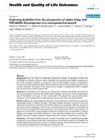
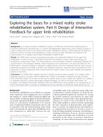
Figure 2(a) depicts an overview of the AMRR system
apparatus. The system uses 11 Opti-Track FLEX:V100
R2 cameras to track 14 reflective markers, shown in
Figure 2(b), worn by the participant on his back,
shoulder blade, acromium process, lateral epicondyle,
and the top of his hand, with 3 additional markers on
the chair. The system tracks the participant’smove-
ment at a rate of 100 Hz, with a spatial resolution of
3.5 - 5.5 mm. Interaction with target objects on the
table is sensed though a capacitive touch sensor within
a button object (used in reach-to-touch tasks) and a n
array of force sensing resistors (FSRs) on a cone object
(used in reach-to-grasp tasks). Embedded FSRs within
the chair monitor the extent of support provided for
the participant’s torso and back. Currently, sensor data
collected by the button object is used in real-time
interaction to d etermine if the task was completed,
while cone FSR data is being collected to inform the
development of objects that provide feedback on
grasping performance. FSR data collected by the chair
is being used to develop a smart chair for monitoring
torso compensation within a home-based training
system.
The system is used by stroke survivors presenting clin-
ical symptoms consistent with left-sided motor area
lesions resulting in right-sided hemiparesis, who were
right hand dominant prior to stroke. Each participant
must demonstrate active range of motion in the right
arm, with the following minimum movement thresholds
to ensure they can complete the reaching task: shoulder
flexion of at least 45°, elbow ROM of at least 30°-90°,
forearm pronation or supination of at least 20°, wrist
extension of at least 20°, and at least 10° active
Lehrer et al . Journal of NeuroEngineering and Rehabilitation 2011, 8:54
/>Page 2 of 21
extension of the thumb and any two fingers. Each parti-
cipant must earn a score greater than 24 on the Mini
Mental State Exam and demonstrate acceptable levels of
audio and visual perception. Our sensory perception test
assesses color blindness, the ability to detect basic prop-
erties of musical sounds, such as pitch, timbre, loudness,
and the ability to perceive structural characteristics of
the feedback such as move ment of images and rhythm
acceleration [13].
A participant receives 1 hour of AMRR therapy, 3
times a week for 1 month, for a total of 12 therap y
training sessions. An average of 8-12 sets of 10 reaches
are practiced per session depending upon the partici-
pant’s ability and fatigue. Between sets the participant is
able to rest, while also interact with the clinician to dis-
cuss the last set. During a therapy training session, the
participantisseatedatatablethatisloweredorraised
to provide various levels of support for the affected arm.
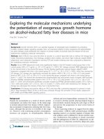
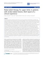
Figure 1 AMRR system overview. The system captures a participant’s movement and extracts key kinematic features identified within the
action representation. This kinematic data is used for computational assessment and generates the interactive feedback. Based on observation
and the computational assessment, the clinician may adapt the system.
Lehrer et al . Journal of NeuroEngineering and Rehabilitation 2011, 8:54
/>Page 3 of 21
The table also allows various target objects to be
mounted and adjusted in location. Visual and audio
feedback is presented on a large screen display with
stereo speakers in front of the participant. While seated
at the table, the participant performs a reaching task to
aphysicaltarget,aconetograsporalargebuttonto
press, or virtual target, which requires the completion of
a reach to a specified location with the assistance of
audiovisual feedback. Physical and virtual target loca-
tions are presented either on the table to train
supported reaches, or raised to variable heights above
the t able to train unsupported (against-gravity) reaches.
At each height, targets can be placed at three different
locations to engage different joint spaces in training.
In virtual training (with no physical target), each reach
begins with a digital image appearing on the screen,
which breaks apart into several minute segments o f the
image, referred to as particles. As the participant moves
his hand towards a target location, the hand’sforward
movement pushes the particles back to reassemble the
Figure 2 System Apparatus and participant marker placement. The system uses 11 Opti-Track cameras (not all cameras shown) to track 14
reflective markers worn by the participant on his back, shoulder blade, acromium process, lateral epicondyle, and the top of his hand, as well as
3 additional markers on the chair.
Lehrer et al . Journal of NeuroEngineering and Rehabilitation 2011, 8:54
/>Page 4 of 21
image and simultaneousl y generates a musical phrase.
Any aspect of the digital feedback, however, may be
turned on or off for reaching tasks to physical targets,
depending on the needs of the participant, to provide
mixed reality tasks and a ssociated training. See addi-
tional file 2: Feedback generation from motion capture,
for an example of feedback generated while a participant
reaches within t he system. The abstract feedback used
within the AMRR system does not directly represent the
reaching task or explicitly specify h ow to perform the
reaching movement (e.g., the feedback does not provide
a visual depiction of a trajectory to follow). Instead,
movement errors cause perturbations within the interac-
tive media that emphasize the magnitude and direction
of the error (e.g ., an excess ively curved trajectory to the
right stretches the right side of a digital image). Promot-
ing self-assessment through non-prescriptive feedback
increases the degree of problem solving by the partici-
pant and encourages the dev elopment of independent
movement strategies [14 ,15]. The abstract feedback also
recontextualizes the reaching task into performance of
the interactive narrative (image completion and music
generation), temporarily shifts focus away from exclu-
sively physical action (and consequences of impaired
movement) and can direct the participant’s attention to
a manageable number of specific aspec ts of his perfor-
mance (e.g., by increasing sensitivity of feedback mapped
to trajectory error) while deemphasizing others (e.g., by
turning off feedback for excessive torso compensation).
The same abstract representation is applied across dif-
ferent reaching tasks (reach, reach to press, reach to
grasp) and various target locations in three-dimensional
space, as viewed in additional file 3: Sy stem adaptation.
Thus the abstract media-based feedba ck provided by the
AMRR system is designed to support generalization or
the extent to which one training scenario transfers to
other scenarios, by providing consistent feedback com-
ponents on the same kinematic attributes across tas ks
(e.g., hand speed always controls the rhythm of the
musical progression), and by encouraging the participant
to identify key invariants of the movement (e.g., a pat-
tern of acceleration and deceleration of rhythm caused
by hand speed) across different reaching scenarios
[16,17].
AMRR Design Methodology
Representation of action and method for quantification
The AMRR system utilizes an action representation,
which is necessary for simplifying the reach and grasp
task into a manageable number of measurable kinematic
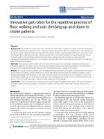
features. Kinematic parameters are grouped into two
organizing levels: activity level and body function level
categories, and seven constituting sub-categories: four
within activity and three within body function, presented
in Figure 3 and as detailed in [12]. The action represen-
tation is populated by key kinematic attributes that
quantify the stroke s urvivor’s performance with respect
to each category of movement. Overlap between cate-
gories in the action representation indicates the poten-
tial amount of correlation among kinematic parameters.
Placement relates to influence on task completion: sub-
categories located close to the center of the representa-
tion have greater influence on goal completion. Each
kinematic attribute requires an objective and reproduci-
ble method for quantitative measurement to be used for
evaluation and feedback generation.
From the three-dimensio nal positions of the markers
worn by the participant, pertinent motion features are
derived and used to compute all kinematic attributes.
The quantified evaluation of these kinematic attributes
is based upon four types of profile references: (a) trajec-
tory reference, (b) velocity referenc e, (c) joint angle
reference and (d) torso/shoulder movement reference.
Each type of reference profile is derived from reaching
tasks performed to the target locations trained within
the AMRR system by multiple unimpaired subjects.
These reference values, which include upper and lower
bounds to account for variation characteristic of unim-
paired movement, are scaled to each stroke participant
undergoing training by performing a calibration at the
initial resting posi tion and at the final reaching position
at the target. Calibrations are performed with assistance
from the clinician to ensure that optimal initial and final
reaching postures are recorded, from which the end-
point position and joint angles are extracted and stored
for reference. Real-time comparisons are made between
the participant’s observed movement and these scaled,
unimpaired reference v alues. Therefore, i n the conte xt
of the AMRR system, feedback communicating “ineffi-
cient movement” is provided when the participant devi-
ates from these scaled unimpaired references, beyond a
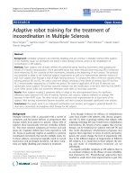
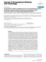
bandwidth determined by the clinician. Figure 4 pre-
sents an example of how magnitude and direction of
error is calculated for feedback generation during a par-
ticipant’s performance of a curved trajectory.
Activity level kinematic features (see Figure 3) are
extracted from the participant’s end-point movement,
monitor ed from the marker set worn on the back of the
hand of the affected arm. These kinematic features,
which describe the end-point’ stemporalandspatial
behavior during a reach and grasp action, are grouped
into four activity level categories: temporal profile, tra-
jectory profile, targeting, and velocity profile. Body func-
tion kinematic features (see Figure 3) are extracted from
the participant’ s movement of the forearm, elbow,
shoulder and torso to describe the function of re leva nt
body structures during a reach and grasp action. Body
function features are grouped into three overarching
Lehrer et al . Journal of NeuroEngineering and Rehabilitation 2011, 8:54
/>Page 5 of 21
categories: compensation, joint function, and upper
extremity joint correlation. Monitoring these aspects of
movement is crucial to deter mining the extent of beha-
vioral deficit or recovery of each stroke survivor. All
kinematic features and corresponding definitions for
quantification within the AMRR system are summarized
in Table 1. Quantification of kinematic attributes within
the representation of action provides detailed informa-
tion on movement performance for generation of the
interactive media-based feedback.
Design of Interactive media-based feedback
The interactive media-based feedback of the AMRR sys-
tem provides an engaging medium for intuitively com-
municating performance and facilitating self-assessment
by the stroke survivor. While each feedback component
is designed to address challenges associated with a spe-
cific movement attribute identified in the representation,
all components are d esigned to connect as one audiovi-
sual narrative that communicates overall performance of
the action in an integrated manner. Following the struc-
ture of the action representation, feedback is prov ided
on performance of activity level parameters and cate-
gories and body function level parameters and categories.
The integration of individual feedback components
through form coherence also re veals the interrelation-
ships of individual parameters and relative contributions
to ac hieving the action goal. Example activity and body
function kinematic features are listed in Table 2 with a
summary of corresponding feedback components and
feature selection used for each feedback component’ s
design [12].
Feedback on activity level parameters and categories
Feedback on activity level parameters must assist with
the movement challenges that most significantly impede
Figure 3 Representation of a reach and grasp action. Kinematic parameters are listed within seven categories: 4 activity level categories (dark
background) and 3 body function level categories (light background).
Lehrer et al . Journal of NeuroEngineering and Rehabilitation 2011, 8:54
/>Page 6 of 21
the efficient performance and completion of a reaching
task. Correspondingly, feedback c omponents reflecting
activity level parameters are the most detailed and pro-
minent audiovisual elements within the AMRR feedback.
Activity Level Category: Trajectory profile Movement
Challenge: Many stroke survivors have difficulty plan-
ning and executing a linear trajectory while efficiently
completing a reaching movement to a target, especially
without visually monitoring movement of the affected
hand [18].
Feedback Components: The animated formation of an
image from particl es, depicted with an emphasis on
visual linear perspec tive, describes the end-point ’spro-
gress to the target while encouraging a linear trajectory
throughout the movement. As the participant reaches,
his end-point’ s decreasing distance to the target
“ pushes” the particles back to ultimately re-form the
image when the target is reached. As the expanded
particles come together, the shrinking size of the
image communicates distanc e relative to the target.
Theshapeoftheoverallimageismaintainedbythe
end-point’s trajectory shape: excessive end-point move-
ments in either the horizontal or vertical directions
cause particles to sway i n the direction of deviation,
which distorts the image by stretching it. Magnitude of
deviation is communicated by how far the particles are
stretched, and direction of deviation is communicated
by which side of the image is affected (e.g., top, bot-
tom, right, left, or combination thereof). To reduce the
distortion of the image, the participant must adjust his
end-point in the direction opposite of the image
stretch. See additional file 4: Visual feedback c ommu-
nicating trajectory, which depicts the visual feedback
generated first by a reach with efficient trajectory, fol-
lowed by a reach with horizontal trajectory deviation
that causes a large distortion on the right side of the
image.
Formation of the image, as the most prominent and
explicit stream among the feedback mappings, not only
provides a continuous frame of reference for trajectory
distance and shape but also communicates progress
towards achieving the goal of the completed image.
Furthermore, by using visual information on the screen
to complete the action, and thus not simultaneously
focusing visually on his hand, the participant reduces
reliance on visual monitoring of his end-point.
Figure 4 Example of tr ajec tory evaluation for feedback generation. x’(t) is the horizontal hand trajectory (measured in cm) along the X’
direction. X
ref
is the trajectory reference, from an average across non-impaired subject trajectories. The dead zone is the bandwidth for non-
impaired subject variation. Trajectory deviation Δx’ within this zone is zero. Feedback on trajectory deviation increases or decreases exponentially
as the hand moves farther away from the dead zone toward the right or left. The rate of change in trajectory deviation is controlled by the
adjustable size of the hull. The wider the hull, the slower the rate of deviation change, resulting in a less sensitive feedback bandwidth. Size of
the hull is adjusted by the clinician depending upon the needs of the participant.
Lehrer et al . Journal of NeuroEngineering and Rehabilitation 2011, 8:54
/>Page 7 of 21
Table 1 Kinematic features and corresponding definitions for quantification
Temporal profile
End-point speed The instantaneous speed at which the endpoint is moving.
Reaching lime The time duration from the initiation of movement until a reach is successfully completed. A reach is completed
when the end-point reaches a specified distance from the target, the end-point velocity decreases below 5% of
the maximum velocity, and the hand activates a sufficient number of sensors on the force-sensing target object
(if a physical target is present).
Speed range The maximum speed of the end-point (within a reach) while moving towards the target from the starting
position.
Speed consistency measure The average variation of the maximum speed (within a reach) over a set of ten reaches.
Reaching time consistency The average variation of the maximum reaching time (within a reach) over a set of ten reaches.
Trajectory Profile
Real-time trajectory error Real-time deviation of the end-point that is greater in magnitude than the maximum horizontal and vertical
deviations within range of unimpaired variation, calculated as a function of the end-point’s percentage
completion of the reach.
Maximum trajectory errors Largest magnitude values among the real-time trajectory errors within a single reach.
Trajectory consistency Measurement of how trajectories vary over several reaches using a profile variation function [28].
Targeting
Target acquisition The binary indicator of finishing the task, achieved when the end-point reaches a specified distance from the
target, the end-point velocity decreases below 5% of the maximum velocity, and the hand activates a sufficient
number of sensors on the force-sensing target object (if a physical target is present).
Initial spatial error approaching
target
The Euclidian distance between the hand position (x, y, z)
hand
and reference curve position (x, y, z)
ref
measured
at the first time the velocity decreases to 5% of the velocity peak, where (x, y, x)
ref
is the reference of the hand
position for grasping the target obtained from adjusted unimpaired reaching profiles.
Final spatial error approaching the
target
The Euclidian distance between the hand position (x, y, z)
hand
and reference curve position (x, y, z)
ref
at the end
of movement, where (x, y, z)
ref
is the reference of the hand position for grasping the target that is obtained
during calibration.
Final spatial consistency Used to measure variation of final spatial error across several trials, and is computed as the square root of
summation of the ending point variances along the x-y-z directions for a set of ten trials.
Velocity Profile
Additional phase number The first phase is identified as the initiai prominent acceleration and deceleration by the end-point, and an
additional phase is defined as a local minimum in the velocity profile beyond the initial phase. The additional
phase number counts the number of phases that occurred beyond the first phase before reach completion.
Phase magnitude Compares the size of separate phases within one reach, and is calculated as the ratio between distance traveled
after the peak of first phase (during deceleration) and the distance over the entire deceleration of the reach
[36]. Only the deceleration part of the first phase is examined because this portion of a reach is where the most
adjustments tend to occur.
Bell curve fitting error Compares the shape of the decelerating portion of the velocity profile to a Gaussian curve by measuring the
total amount of area difference between the two curves.
Jerkiness Measure of the velocity profile’s smoothness, and is computed as the integral of the squared third derivative of
end-point position [37].
Compensation All compensation measures are computed as a function of the end-point’s distance to target because the
extent of allowable compensation varies throughout the reach [38].
Torso flexion Compares the flexion of the torso relative to the non-impaired subjects’ torso forward angular profile, adjusted
to participant-specific start and end reference angles determined by a clinician during calibration.
Torso rotation Compares the rotation of the torso relative to the non-impaired subjects’ torso rotation angular profile, adjusted
to participant-specific start and end reference angles determined by a clinician during calibration.
Shoulder elevation Compares the elevation of the shoulder relative to the non-impaired subjects’ shoulder elevation profile,
adjusted to participant-specific start and end reference angles determined by a clinician during calibration.
Shoulder protraction Compares the protraction of the shoulder relative to the non-impaired subjects’ shoulder protraction profile,
adjusted to participant-specific start and end reference angles determined by a clinician during calibration.
Pre-emptive elbow lift Computed as the difference between current elbow position and the elbow position during rest calibration.
Elbow lifting is only examined at the beginning of the reach as a predictive measure of initiation of the
movement through compensatory strategies.
Joint Function Joint angles of the shoulder, elbow and forearm are evaluated based on the following measures
Range of motion (ROM) The difference in angle from the initiation to the completion of the movement.
ROM error The difference between the ROM of an observed reach and the reference ROM obtained during the assisted
calibration reach.
Lehrer et al . Journal of NeuroEngineering and Rehabilitation 2011, 8:54
/>Page 8 of 21
Principles Applied: Visual feedback is best suited for
communicating three-dimensional spatial information.
Particle movemen t is directly linked to end-point move-
ment in order to explicit ly describe the end-point’sspa-
tial deviation from or progress towards achieving an
efficient trajectory to the target. The feedback is deliv-
ered concurrent to action and continuously to allow the
participant to observe movement of his end-point by
monitoring formation of the image, and when needed,
apply this information for online control of his move-
ment to adjust for vertical or horizontal deviations.
Movement Challenge: Sometimes stroke survivors are
unable to utilize online information during task execu-
tion to develop a movement strategy, and require
feedforward mechanisms to assist with planning pro-
ceeding movements.
Feedback Components: A static visual summary com-
municates overall maximum traject ory deviation after
each reach is completed to facilitate memory of real-
time trajectory error. The summary presents a s eries of
red bars. Their location on the screen (e.g., high, low,
left, right, or combinations thereof) represents where
error occurred in terms of vertical and horizontal coor-
dinates (along the x, y axes respectively). Visual perspec-
tive is used to communicate the distance at which error
occurred (along the z axis) through spatial depth. A
deviation occurring in the beginning of the movement
appears closer to the viewer in perspective space, while
Table 1 Kinematic features and corresponding definitions for quantification (Continued)
Real-time error The maximum error between the observed joint angle curve during a reach and the reference curve derived
from non-impaired reaching data that is scaled to the start and end reference angle of each participant.
Consistency of the angular profile The average variation between angular profiles within a set often reaches.
Upper extremity joint
correlation category
Measures synergy of two different joints moving in a linked manner, computed using the standard
mathematical cross-correlation function of two angles over the duration of a reach for each pair listed below.
May be compared to non-impaired upper extremity joint correlations for evaluation [39].
Shoulder flexion and elbow
extension
Measured cross-correlation between shoulder flexion and elbow extension
Forearm rotation and shoulder
flexion
Measured cross-correlation between forearm rotation and shoulder flexion
Forearm rotation and elbow
extension
Measured cross-correlation between forearm rotation and elbow extension
Shoulder abduction and shoulder
flexion
Measured cross-correlation shoulder abduction and shoulder flexion
Shoulder abduction and elbow
extension
Measured cross-correlation between shoulder abduction and elbow extension
Table 2 Key kinematic features with corresponding feedback components and feature selection [12] applied within
feedback design
Activity Level Kinematic
Features
Corresponding Feedback
Components
Primary Sensory
modality
Interaction time
structure
Information
processing
Application
Trajectory 1.Magnitude and direction of image
particle movement
2.Harmonic progression
3.Summary of error
1.visual
2.audio
3.visual
1.concurrent
continuous
2.concurrent
continuous
3.offline terminal
1.explicit
2.implicit
3.explicit
1.online control
2.feedforward
3.feedforward
Speed Rhythm of music audio concurrent
continuous
implicit feedforward
Velocity Profile Image formation integrated with
musical progression
audiovisual concurrent
continuous
extracted feedforward
Body Function Level
Kinematic Features
Forearm rotation Image rotation visual concurrent
continuous
explicit online control
Elbow extension Volume and richness of orchestral
sounds
audio concurrent
continuous
implicit online control/
feedforward
Torso compensation Abrupt disruptive sound audio concurrent
intermittent
explicit online control
Joint correlation Temporal relationship among
feedback mappings
audiovisual concurrent
continuous
extracted feedforward
Lehrer et al . Journal of NeuroEngineering and Rehabilitation 2011, 8:54
/>Page 9 of 21
deviations that occur later appear further away. The
number of red bars conveys the magnitude of trajectory
error. See the inefficient reach presented in additional
file 4: Visual feedback communicating trajectory, for an
example visual summary indicating horizontal trajectory
error following the completion o f the image. Trajectory
deviation is summarized from rest position until the
hand’s entrance into the target zone (an adjustable area
surrounding the target that determines task completion),
excluding the fine adjustment phase, as it likely does not
contribute to feedforward planning of the reaching tra-
jectory [19].
Principles Ap plied: Visual pe rspective is used to com-
municate the reaching distance as spatial depth. The
summary provides an abbreviated history of the conti n-
uous particle movement by explicitly illustrating the
magnitude (number of bars) and direction (location on
screen) of traj ectory errors. Presenting an offline term-
inal visual summary allows the participant to make an
overall comparison of timing, location and magnitude of
his traject ory deviations within the context of the entire
reach. This display may also facilitate the implicit pro-
cessing of the connection to me mory of performance on
other aspects of movement (e.g., the participant remem-
bers hearing a shoulder compensation sound indicator
in the beginning of the reach, and also sees red error
bars on the top of the screen within the summary).
Connecting real-time movement to offline contempla-
tion can inform feedforward planning of successive
movements.
Activity Level Category: Temporal profile Movement
Challenge: From the volitional initiation of movement
until the completion of the reaching task, stroke survi-
vors often have difficulty planning and controlling accel-
eration, trajectory speed, and deceleration of their
movement across a defined space. This challenge makes
relearning efficient movement plans difficult.
Feedback C omponents: The musical phrase generated
by the participant’s movement is designed to help moni-
tor and plan the timing of movement, as well as encou-
rage completion of the actio n goal. The end-point’ s
distance to the target controls the sequence of chor ds of
the musical phrase. The reach is divided into four sec-
tions with different musical chords played for ea ch. The
sequence of chords follows a traditional musical pattern
(with some randomized variation to avoid repetitiveness)
that underlies many popular songs and is thus more
likely to be familiar to the participant. The participant
may intuitively associate each part of the reach (early,
middle, late) with a corresponding part of a musical
sequence and be motivated to finish the reaching task to
complete a familiar audio composition. If the end-point
deviates from an efficient trajectory tow ards the tar get,
the musical chords detune for the duration of deviation
to place in time the occurrence of the deviation
(whereas the spatial information of the deviation is com-
municated by the image stretching). See additional file 5:
Audiovisual feedback communicating trajectory and
speed, in which an efficient reach is followed by a reach
with detuning as a result of trajectory deviation. Note
how the addition of sound can be used to facilitate
awareness of the timing of error, while the visuals
accentuate error magnitude and direction.
End-point speed is mapped to the rhyt hm of the
musical phrase. The participant’ s mov ement speed
results in a “ rhythmic shape” (change of rhythm over
time)thatmoststronglyencodestheend-point’s accel-
eration during reach initiation, the deceleration when
approaching the target, and the overall range of speed.
In additional file 5, compare the sonic profile of the last
slow reach to the sonic profil e of the comparatively fas-
ter first reach, which has a noticeable acceleration/decel-
eration pattern and desired velocity peak. Memory of
the resultant rhythmic shape (i.e., which rhythmic pat-
tern is associated with the best reaching results) can
assist the participant to develop and internalize a repre-
sentation of end-point speed that helps plan h is
performance.
Principles Applied: Audio feedback is best suited for
communicating temporal movement aspects. Musical
feedback is controlled by the end-point’s speed and dis-
tance, and communicates the end-point’ s concurrent
progress towards the target in a continuous mann er. In
accompaniment to explicit visual monitoring of the
image formation, the audio feedback communicates
changes within the end-point’s temporal activity and
encourages implicit information processing of the
rhythm as a singular, remembered form (i.e., memory of
the rhythmic shape). Memory of the musical phrase
supports feedforward mechanisms fo r planning f uture
movements and facilitat es comparison across multiple
rea ches (e.g., speed consistency of reaches within a set).
The detuning of the harmonic progression adds a time-
stamp to the visual stretching of the image to ass ist
feed-forward planning.
Activity Level Category: Velocity Profile
Movement
Challenge:
Many stroke survivors do not exhibit a bell-
shaped velocity profile characteristic of unimpaired
reaching movements as a result of difficulties with tim-
ing and executing an efficient trajectory.
Feedback Components: Simultaneous feedback streams
describing the participant’s end-point behavior can h elp
the participant in relating the temporal and spatial
aspects of his reach. The acceleration/deceleration pat-
tern communicated by the rhythmic shape of music
assists the participant in understanding speed modula-
tion. The shrinking size of the image and harmonic pro-
gression communicate his distance and overall timing to
Lehrer et al . Journal of NeuroEngineering and Rehabilitation 2011, 8:54
/>Page 10 of 21
reach the target . Coupling these simultaneous mappings
all ows for changes in speed to be connected to distance
and facilitate the development of an integrated space-
time plan. Figure 5a-e illustrates how (a) the end-point’s
progress to the target in the physical space is described
by the (b) image progression, (c) harmonic progression,
and (d) rhythmic progression, which communicate (e)
velocity profile as an extracted, integrated descriptor of
the end-point’s distance, direction, and speed towards
the target.
Principles Applied: As a complex aspect of movement,
the velocity profile cannot be effectively expressed as a
singular feedback component, for a singular mapping
would not allow the participant to determine which
aspect of movement (speed, direction, and/or distance)
require s adjustment that generalizes to multiple types of
reaching tasks. Therefore, feedback on the velocity pro-
file is observed through extracted information proces-
sing, in which the participant integrates information
from both visual and audio streams reflecting directed
distance and speed. Form integration of relevant audio
and visual mappings into a unified velocity profile is
encouraged by feedback feature selection: all involved
comp onents are concurrent and continuous mappings of
end-point movement [12]. Extracted information proces-
sing of the velocity profile may facilitate feedforwar d
planning of acceleration and deceleration patterns along
a given reaching distance to a target.
Feedback on body function level parameters and
categories
Body function level feedback must assist with challenges
impeding the relearning of premorbid movement patterns
of specific body structures relevant to reach and grasp per-
formance. Feedback on body function parameters is coarse
and discrete, thereby temporarily directing attention to
specific body structures without distracting from complet-
ing the action goal. When a clinician must focus training
Figure 5 Three parallel feedback streams communicate the spatial and temporal behavior of the end-point. The z’ distance to target (a)
is the shortest physical distance the end-point must travel from rest position (z’ = 0) to reach the target (z’ = 1). Based on distance traveled, the
end-point’s location along z’ prime controls the (b) size of the image formation (image progression) as well as which (c) chords are played
(harmonic progression). The rhythmic shape or (d) rhythmic progression is controlled by the end-point’s speed. These simultaneous feedback
streams can form an integrated descriptor of the (e) velocity profile.
Lehrer et al . Journal of NeuroEngineering and Rehabilitation 2011, 8:54
/>Page 11 of 21
on regaining functional independence primarily through
teaching compensatory mechanisms, training for improved
body function may not be appropriate [20,21]. Accord-
ingly, in the AMRR system, body function mappings can
be independently toggled on or off at the discretion of the
clinician. Examples of each of the following feedback com-
ponents may be fou nd in additional file 6: Forearm rota-
tion, elbow extension, and compensation.
Body Function Level Category: Joint function
Movement Challenge: Many stroke survivo rs cannot
achieve the appropriate timing or range of forearm pro-
nation to complete a reach and grasp task.
Feedback Components: Feedback on forearm rotation is
related to end-point activity by controlling the angle of
image o rientation while particles co me together to fo rm the
image. Image rotation is controlled by the difference
between reference forearm orientation an gle s at a given dis-
tance to the target and the observed forearm orientation.
Excessive supination causes c lockwise rotation, while exces-
sive pronation causes counter-clockwise image rotation. The
size of the rotated image communicates where forearm rota-
tion error occurred relative to the distance f rom the target.
Principles Applied: Visual feedback communicates
forearm spatial orientation in an explicit manner, which
provides concurrent, contin uous information throughout
the reach to assist the participant’s online control.
Movement Challenge: Many stroke survivors have dif-
ficulty w ith sufficiently extending t he elbow and appro-
priately timing elbow extension.
Feedback Components: P ercentage of elbow extension
is mapped to a musical sequence performed by a digi-
tized orchestra. In additio nal file 6 listen for the orches-
tral sound increasing in volume, range of pitch, and
harmonic richness as th e percentage of elbow extension
increases and the image completes.
Principles Applied: Communication of elbow extension
is provided as audio feedback to assist with tim ing of
movement. Percentage elbow extension is mapped in a
continuous manner, which communicates changes in
magnitude of extension within a reach. Elbow extension
feedback is provided concurrently to movement and may
be used fo r online control and/or memory of its temporal
relationship to other mappings can be used fo r feedfor-
ward planning. Underscoring achievement with an
increasingly rich orchestral sound is a standard technique
of film scoring [22]. Through implicit information pro-
cessing, memo ry of successful reaches may be compared
with the orchestral quality of other reaches within a set.
Body Function Level Category: Shoulder and Torso
Compensation
Movement Challenge: To compensate for lack of exten-
sion during a reach, many stroke survivors use excessive
shoulder movement (elevation and/o r protraction) and
excessive torso movement (flexion and/or rotation).
Feedback Components: Compensatory movements are
signaled by distinctive sounds that can interrupt the
musical phrase (foreground) generated by end-point
movement. Excessive shoulder compensation during a
reach causes a cymbal sound while excessive torso com-
pensation causes a crackling sound. These compensation
indicators may be enabled individually or simulta-
neously, and are activated when the participant moves
beyond an acceptable range of movement. Because these
sounds do not combine well with the musical fore-
ground in terms of harmony, timbre and rhythm, they
draw the participant’s attention to body structures exhi-
biting inefficient movement strategies.
Principles Applied: Unique audio f eedback indicators
provide explicit indication of either shoulder or torso
compensation concurrent to action for online control
and correction of error. These auditory cues allow for
intermittent monitoring of specific body functions
amidst continuous end-point monitoring. As audio indi-
cators, implicit information processing of these sounds
caused by compensatory movements may be integrated
into memory of the overall musical phrase and overall
performance to assist with feedforward planning.
Body Function Level Category: Upper extremity joint
correlation
Movement Challenge: Lack of intersegment al joint coor-
dination while reaching for an object in three-dimen-
sional space often results in inappropriate timing of
movement at each joint.
Feedback Components: The relationship among differ-
ent audio mappings connects individual joint function
to end-point behavior. During a successful reach, as the
target is approached, the rhythmic progression driven by
the end-point decreases in speed, and the volume and
richness of orchestral strings mapped to elbow extension
increases. The peak of orchestral richness is reached at
the completion of the grasp and is synchronous to the
image completion, the music progression resolution, and
the sounding of the success cue (triangle sound), as
demon strated in the first reach in additional file 7: Joint
Correlation Examples. The orchestral sound and fore-
ground music follow the same harmonic progression,
which facilitates their integration. The memo ry of this
desired synchronization assi sts the learning of a coor di-
nation schema fo r elbow extension in relation to end-
point trajectory, velocity, and goal completion. Other
body function level feedback events, such as the com-
pensation indicator sounds, can also be placed in time
along the course of th e reach relative to t he rhythmic
and harmonic m usical progression driven by the end-
point, and/or related to the lack of orchestral sound. For
Lehrer et al . Journal of NeuroEngineering and Rehabilitation 2011, 8:54
/>Page 12 of 21
example, in the second reach of additional file 7, t he
shoulder compensation sound is followed by image
stretching and the detuning sound, indicating that early
shoulder compensation was followed by later deviatio n
of the end-point trajectory. Through experience with
the feedback over time, memory of this relationship may
occur as an extracted information process by the user.
Principles Applied:Music(audio) is a very effective
communicator of temporal relationships between sepa-
rate but parallel events [23]. Multiple relationships
between musical lin es (e.g., foreground melody versus
background accompaniment) and individual sounds (e.
g., percussive sounds related to body function) can be
easily observed by listeners concurrently to their move-
ment, and remembered for extracted processing after
the event [24,25]. The intuitive memorization of the
musical relationships can facilitate feedforward planning
[26,27]. Continuous feedback streams that should be
correlated are given different individual characteristics
(e.g. timbre, rhythm) but follow a similar harmonic pro-
gression. Intermittent feedback indicators are used that
can be related to continuous detailed feedback yet can
still be identified as separate events.
Integrating individual feedback components
through form coherence
The connection between feedback components and cor-
responding movement components must be intuitive
and easily perceived. Simplifying training by only offer-
ing feedback on one element at a ti me is not an optimal
solution. Some stroke survivors cannot connect indivi-
dually learned aspects of performance into a complete,
gen eraliza ble, sust ainable strategy [20]. The higher-level
organization of the feedback must facilitate integration
of multiple medi a components into one coherent media
narrative [13].
Asshownintheprevioussection,theAMRRsystem
facilitates integration of multiple media streams through
(a) appropriate selection of feature choices for feedback
mappings (e.g., audio for time, visuals for space), (b)
compositional strategies that integrate closely related
streams (e.g., time and space eleme nts of velocity pro-
file), and (c) parallel action and feedback narratives (e.g.,
successful completion of the physical action g oal com-
pletes the interactive media narrative). These three stra-
tegies establish formal coherence between action and
media.
Adaptive training methodology
TheAMRRsystemishighlyadaptabletomaintainan
appropriate level of challenge and engagement based on
a participant’s impairment and progress. Numerous
combinations of mediated feedback and task types allow
for a wide variety of training scenarios for each
participant.
Adaptable components of the AMRR system
The primary components of the AMRR system that may
be adapted include target type and location, selection
and sensitivity of media components, and training envir-
onment. Three task types are trained within the AMRR
system: reach, reach to push a button, and reach to
grasp a cone. Different task types may be applied for
focused training of specific aspects of movement, such
as encouraging increased speed by using a button
instead of a cone as t he target. Various target locations
engage different joint spaces in training. The four pri-
mary target locations used within the AMRR system
include supported (on the table) ipsilateral (SI), sup-
ported lateral (SL), against-gravity (elevated from table)
ipsilateral (AGI), and against-gravity lateral (AGL), listed
in order of complexity of joint space utilized.
Training is conducted in sets of ten reaches. Task type
and feedback may be adjusted after each set. The clini-
cian may guide the tra ining focus for each set by select-
ing which media components to use. The clinician’ s
choices also control the level of feedback complexity
provided to the participant. Furthermore the sensitivity
of each enable d feedback componen t may be indepen-
dently adjusted, which allows the clinician to set the
appropriate level of difficulty for each movement attri-
bute. A hull is the adjustable amount of error in a parti-
cipant’s movement that the system will tolerate before
giving feedback showing error (Figure 4). Adjustable,
three-dimensional hulls control the feedback sensitivity
for trajectory, joint function, and c ompensation [28].
The peak rhythm of the musical phrase may also be
scaled to a desired maximum hand speed determined by
the clinician.
Different training environments may be used within
the AMRR system by controlling the amount of
media-based feedback (virtual) and task (physical)
components applied. The AMRR system provides for
gradual transitions between virtual and physical train-
ing by using three types of training environments: phy-
sical (provides no media-based feedback while r eaching
to a physical target), hybrid (provides combinations of
media-based feedback while reaching to a physical tar-
get) and virtual (requires interaction with only media-
based feedback and no physical target). Multiple avail-
able variants (gradations) of these environments enable
the clinician to shift training on a continuum towards
a more virtual (for recontextualization [12]) or more
physical (for reduced or no fe edback guidance) envir-
onment depending upon the participant’ s needs and
stage of training.
Lehrer et al . Journal of NeuroEngineering and Rehabilitation 2011, 8:54
/>Page 13 of 21
Overview of adaptive training
Before training with the AMRR system begins, a partici-
pant is evaluated by the evaluating clinician and an
attending physician to determine and rank the move-
ment aspects requiring focused training. This collection
of movement aspects from the preliminary assessment is
called the impairment prof ile and may be used to guide
the adaptive training. For each set of ten reaches, the
treatment clinician typically chooses one or two limita-
tions from the limitation profile on which to focus.
Assisted by the media specialist, the clinician may then
select the appropriate task components (target type and
location), media-based feedback components (which
feedback components to enable and respective sensitiv-
ities) and type of training environment (virtual, hybrid,
physical) to ut ilize for training. Sequential modifications
of these training components and movement aspects
form the adaptive training. After each set, the system’s
quantitative evaluation, coupled with the clinician’ s
direct observation, inform the adaptation decisions for
the proceeding set. The AMRR system’s ability to adapt
along several dimensions throughout training allows for
a customized training experience for each participan t.
For more description on the dynamics of training in
application please refer to Chen et al, in which two
example patient case studies are presented [16].
The study protocol has been reviewed and approved
by the Institutional Review Board at Arizona State Uni-
versity. All participants s igned a consent statement and
authorization forms. Copies of these signed forms are
available for review by the Editor-in-Chief of this journal
upon request. No participant’s facial identity is revealed
within the media associated with this manuscript.
Methods for Outcome measurement & Data
analysis
Training using the AMRR system is evaluated using
changes in kinematic performance and standard clinical
assessments as outcomes, each of which are measured
prior to and after four weeks of training. Kinematic per-
formance is measured from 10 reaches, unassisted by
feedback, to each of the 4 trained target locations for a
tot al of 40 reach es. Full clinica l assessments include the
Motor Activity Log (MAL) , the Stroke Impact scale
(SIS), the upper extremity po rtion of the F ugl-Meyer
Assessment (FMA), and the Wolf Motor F unction Test
(WMFT) [29-32].
Pre and post values are presented here from the
WMFT and the up per extremity motor function portion
of the Fugl-Meyer Assessment. The WMFT consists of
a series of functional tasks relevant to activities of daily
living that are timed and rated for quality by the evalu-
ating clinician [32]. The FAS rating scale ranges from 0
= no attempt to 5 = normal movement. The rating scale
for the Fugl-Me yer Assessm ent ranges from 0 = cannot
perform to 2 = performs completely [31].
Supportive kinematic data are provided within this
paper to demonstrate successful application of the sys-
tem’ s feedback components to achieve focused and
integrated improvements in three representative parti-
cipants with different movement impairments. The raw
pre and post training measurements of 12 kinematic
features related to activity and body function move-
ment aspects trained using the AMRR feedback are
presented with respect to the three participants’ train-
ing needs. Pre and post kinematic performance were
analyzed using the Wilcoxon rank-sum Test due t o the
small sample number of reaches [33]. Statistical signifi-
cance was measured at a =0.05anda = 0.01, and to
account for multiple comparisons acro ss 12 kinematic
parameters, at a = 0.004 and a = 0.0008.
In addition to kinemati c measures and standard clin i-
cal assessments for evaluation, methods are being devel-
oped to better gauge the added value of AMRR
feedback to rehabilitatio n training on the level of indivi-
dual reaches (trials). Individual trials are co mpared in
sequential pairs to evaluate the correlation between
observable feedback in one trial and improved perfor-
mance of kinematic variables in the trial immediately
fol lowing. Percentage improvement in performance of a
specific kinematic variable after the presence of feedback
was calculated as follows:
1. A trial k was selected if performance of a kine-
matic variabl e deviated beyond a threshold deter-
mined from movement references measured from
unimpaired individuals.
2. Within these selected trials, if error feedback was
triggered, the trial k was classified as with feedback
(FB). If the error feedback was not triggered (due to
low feedback sensitivity) or the feedbac k component
was turned off for that trial, the trial k was classified
as no feedback (NFB).
3.ForthetworesultingsetsofFBandNFBtrials,
the mean performance of all initial trials k (pk
mean) was compared to the mean performance of
all immediately following trials k+1 (pk+1 mean)by
calculating the percentage change:
% change
within FB set
= 100*(p
k+1 mean, FB set
− p
kmean,FB set
)/p
kmean,FB set
% change
within N
FB
set
= 100*(p
k+1 mean, NFB set
− p
kmean,NFB set
)/p
kmean,NFB se
t
4. The difference in percentage improvement
between the NFB and FB sets of trials was calcu-
lated:
Lehrer et al . Journal of NeuroEngineering and Rehabilitation 2011, 8:54
/>Page 14 of 21
difference in % improvement
FB-NFB
= % change
within
FB
set
− % change
within
NFB
set
.
Supportive Data
Results are presented from the pre an d post evaluations
of th ree stroke survivors who have each trained with the
AMRR system for a period of 12 weeks. Table 3 lists
demographic information and lesion type of the three
participant stroke survivors, each o f whom was right-
sided hemiparetic. Based on the pre-training evaluation,
a unique impairment training profile was det ermined by
the physical therapist and attending physician for each
participant. Table 4 lists the ranked movement aspects
of each participant’s impairment profile. For each set
during training, the clinician determines the movement
focus and selects the appropriate feedback components
and sensitivity to use. Table 4 includes the correspond-
ing distribution of resulta nt focused training on relevant
movement aspects, presented as percentages of total sets
completed within the 12 week training period.
Figure 6 displays the results from the Wolf Motor
Function Test (WMFT) and motor function section of
the Fugl-Meyer Assessment (FMA) performed prior to
and after training. All three participants increased their
average FAS, indicating an increa sed quality of move-
ment as rated by the evaluation therapist, as well as
decreased the total time required for task completion
among the tasks tested. Each participant also improved
his or her Fugl-Meyer motor function score as well.
Figure 7 presents the average changes in kinematic
performance for both activity and body function level
movement aspects, measured prior to and immediately
following AMRR training. Measurements are taken
from a set of ten reach to grasp movements, unassisted
by feedback, using a cone located at the midline and
elevated 6 inches off the table. The level of significant
difference between the pre and post training measure-
ments is indicated next to ea ch participant number.
Movement aspects that received training focus are
indicated. Despite differences among training regimens,
all 3 participants experienced significant improvement
not only in movement aspects that received focused
training, but also in movement aspects that were
beyond training focus areas.
Among the kinematic parameter s listed in Figure 7,
trajectory error, shoulder compensation, torso compen-
sation, and sup ination error each are mapped to
concurrent feedback that is designed for explicit awar e-
ness of performance. Thus error feedback on these attri-
butes can be utilized immediately by the participant to
correct movement performance in a subsequent trial.
For these attributes, Table 5 lists the difference in per-
centage improvement between adjacent reaches when
feedback was present versus when feedback was not.
Cells with bolded text indicate percentages of improve-
ment for a kinemat ic parameter given its corresponding
feedback mapping. For most of the variables listed, kine-
matic performance improved more (indicated by the
positive percentage listed) following erroneous trials that
triggered its corresponding feedback as compared to fol-
lowing trials that did not have this feed back mapping
expressed. For all 3 participants, for example, forearm
rotation error improved by more in trials that followed
the triggered feedback mapping for forearm rotation
error (i.e. image rotation) as compared to following
trials with error in forearm rotation that did not trigger
the feedback. Similar patterns of improvement can be
seen for all 3 participants for vertical trajectory error
and torso compensation, indicated by the bolded values
demonstrating positive percentage improvement.
Table5alsoliststhedifferencein%improvement
for feedback versus no feedback trials in the perfor-
mance of a given kinematic variable following the trig-
gering of feedback mapped to different kinematic
variables (cells with n on-bolded values). For example,
for all 3 participants, torso forward compensation
improved more after trials that triggered feedback on
horizontal or vertical trajectory error (i.e. horizontal or
vertical image stretching) than after trials that had sig-
nificant torso compensation error but did not trigger
image stretching.
Discussion
Table 4 demonstrates that although a participant’s
impairment profile can inform training, the resultant
training dynamics are highly catered to an individual’ s
progress and therefore may deviate from the initial
impairment profile. Because the clinician can dynami-
cally adapt AMRR training to respond to the partici-
pant’ s needs within or across sessions, training can
focus on movement aspects that deviate from those
listed within the impairment profile. Furthermore, the
training distribution (number of sets that are focused on
each movement attribute) does not necessarily reflect a
Table 3 Participant demographics and lesion type
Age Months post-stroke Sex Lesion
Participant 1 76 6 Female left basal ganglia & periventricular white matter infarct
Participant 2 74 7 Male left-sided middle cerebral artery infarct
Participant 3 66 6 Male multifocal embolic left hemispheric cerebral infarctions
Lehrer et al . Journal of NeuroEngineering and Rehabilitation 2011, 8:54
/>Page 15 of 21
movement attribute’s rank in the initial impairment pro-
file, as indicated in Table 4.
The generalizable value of AMRR training is sup-
ported by improve ments in both the WMFT FAS scores
(Figure 6) and kinematic measures (Figure 7) across the
three participants, since the tasks trained in reach and
grasp are not the same as the tasks assessed in the
WMFT FAS. Due to the small number of samples, no
statistical comparisons are provided. Though Participant
3 was able to achieve the most improvement in the
motor function section of the Fugl-Meyer assessment,
the other two participants, rated with lower impairment
levels, may have made more gains had the training per-
iod been extended beyond twelve sessions.
Table 4 and Figure 7 demonstrate that customized
approaches to training can result in kinematic improve-
ments for particip ants of diffe rent impairment. Though
each participant experienced training with different
focus distributions, each participant improved across
almost all of their respective focus areas. The exceptions
are Participants 1 and 3 who did not improve in hori-
zontal trajectory, which may be related to more atten-
tion given to accuracy with respect to the target’ s
elevation, and Participant 1 who did not increase in
speed, but remained within close range of 0.5 m/s. All
participants improved in multiple aspects of movement
that were not designated as focus areas as well.
An example of training using feedback on correlated
aspects of movement can be seen in Participan ts 2 and
3, who each began training with insufficient elbow
extension as a top-ranked movement impairment and
experienced most of his focused training in torso com-
pensation. This example illustrates how a more direct
mapping encouraging explicit information processing on
torso compensation was also utilized to promote elbow
extension. Multiple types of feedback (e.g. feedback
encouraging explicit versus implicit processes) catered
in design to communicate performance of specific
aspects of movement (trajectory versus joint relation-
ships) can allow for both targeted and integrated train-
ing of multiple mov ement aspects. For example, in
Participant 2’ s training, feedback on trajectory and
speed were utilized to train individual performance
aspects with resulting improvements, or were utilized in
parallel to focus on training velocity bellness, which also
improved. Improvement in joint correlation also utilized
the integration of individual intermittent mappings in
the context of continuous strea ms of activity level feed-
back in all 3 participants, for example, to improve per-
formance of both individual joint function and
integrated joint correlation.
Training also accommodates focus on activity level
versus body function level movement aspects. Partici-
pant 1, rated with mild impairment, was able to main-
tain the majori ty of her activity level performance while
improving all of her body le vel aspects that related to
focused training. While over half of Participant 2’s train-
ing focused in torso compensation and elbow extension,
Table 4 Participant baseline impairment and resultant training distribution
Rated Overall Impairment Ranked Movement Aspects of Impairment Profile Related Movement
Features
%
focused
training
Participant 1 Mild 1. Torso and shoulder compensation Shoulder compensation 35.09
2 Inconsistency of elbow extension Peak speed 15.00
3. Insufficient elbow extension Torso compensation 12.57
4. Trajectory Targeting 9.65
5. Joint Synchrony Others 9.52
Elbow extension 9.11
Trajectory 9.06
Participant 2 Mild to moderate 1. Insufficient elbow extension Torso compensation 28.9
2. Insufficient shoulder flexion Elbow extension 23.2
3. Insufficient speed Others 20.2
4. Slow initiation of movement Trajectory 12.5
5. Torso compensation Peak speed 8.1
Velocity bellness 7.1
Participant 3 Moderate 1. Insufficient elbow extension Torso compensation 21.5
2. Insufficient shoulder range of motion Others 20.6
3. Shoulder and torso compensation Trajectory 19.1
4. Ataxia Elbow extension 18.2
5. Targeting Velocity bellness 12.7
Joint correlation 7.9
Lehrer et al . Journal of NeuroEngineering and Rehabilitation 2011, 8:54
/>Page 16 of 21
he experienced significant improvements across most
features presented in both body function and activity
level training. Participant 2’s significant worsening in
shoulder compensation could potentially be a ddressed
with lo nger treatment periods allowing for focused
training on this parameter.
Table 5 presents increased percentage improvement in
kinematic performance for most kinematic-feedback
mapping pairs (bolded values) across all 3 participants.
These results reveal in dices that concurrent AMRR
feedback designed for explicit understanding on perfor-
mance of a given kinematic variable can lead to immedi-
ate self-assessment and increased correction for that
targeted aspect of movement. Furthermore, the correla-
tion between increased improvements in a kinematic
parameter a nd the presence of feedback mapped to dif-
ferent kinematic parameters may suggest that AMRR
feedback promotes integrated training; it can allow the
user to derive relationships between different aspects of
movement through an extraction process (i.e. gain
understanding after longer term experience with
multiple feedback components), such as the effect of
proximal body movements on distal end-point activity.
Differences among the participants’ performance
improvements in relation to the triggered feedback
demonstrates that the effectiveness of each feedback
mapping can vary by user, providing support that an
adaptable feedback paradigm catering to the needs of
each participant is necessary.
Future work will include analysis o f relationships
between other feedback mappings that encourage more
implicit processes (e.g. elbow extension, joint c orrela-
tion, velocity profile) and correlated performance
improvements. These aspects of movement, which
require longer experience with the system, must in turn
be assessed across multiple trials or sessions.
The AMRR system has been used and accepted by
both stroke survivors and clinicians through a series o f
studies that demonstrate its reliability and validity
[13,16,17] . We h ave discussed the experi ences with all
stroke survivors and clinicians that have used and are
currently interacting with the system, and utilize their
Figure 6 Changes in the Wolf Motor Function (WMFT) and Fugl-Meyer Assessment. (a) WMFT average Functional Ability Score (FAS), (b)
WMFT total time, and (c) Fugl-Meyer Motor Function Assessment score
Lehrer et al . Journal of NeuroEngineering and Rehabilitation 2011, 8:54
/>Page 17 of 21
feedback for improvement. This is a continuous process,
as new user s offer valuable feedback for the improve-
ment of the system’s design. Thus, we are considering
the development of a more standardized qualitative eva-
luation of the system by the users. Additionally, feed-
back on grasping is under current development, as well
as feedback that elicits reaction without causing tension,
so that we can consider reaction time as part of our
evaluatio n. Knowledge gained through application of the
clinical system design in practice also informs the devel-
opment of a home-based rehabilitation system.
Currently a home-based adaptive mixed reality rehabi-
litation (HAMRR) system is under development that
uses the design principles of the AMRR system to allow
stroke survivors to continue their treatment over multi-
ple months of therapy at home. Multimodal sensing
Figure 7 Average changes in kinematic parameters measured prior to and following 12 sessions of training with the AMRR system.
Raw mean values are presented for the unsupported (6-inches above the table surface) cone target located at the participant’s midline, which is
one of four target locations evaluated during the pre and post evaluation sessions.
Lehrer et al . Journal of NeuroEngineering and Rehabilitation 2011, 8:54
/>Page 18 of 21
methods and audiovisual feedback p rovide concurrent
and summary information on task performance to assist
the stroke survivor in sel f-assessing his movement.
Within each week of training, a computational adaptation
component automatically customizes weeklong therapy
sessions based on a clinician’s goals for the stroke survi-
vor. The adaptation is structured as a semi-supervised
framework, using a probabilistic graphical network repre-
sentation based on [34]. The system archives perfor-
mance evaluations of the stroke survivor’sprogressfor
the clinician to review remotely on a weekly basis and
adjust training accordingly. After the therapist reviews
the stroke survivor’s movement evaluation, he or she can
customize parameters in the adaptation framework, such
as training focus and sequence, which will further inform
the automatic adaptation used within weekly training.
The HAMRR system is scheduled for testing by stroke
survivors in their homes in the fall of 2011.
Conclusions
The methodology for designing a mixed reality system for
stroke rehabilitation discussed in our companion paper
[12] has been applied for the development of an Adaptive
Mixed Reality Rehabilitation (AMRR) system for upper
extremity rehabilitation of stroke survivors. The AMRR
system provides evaluation and adaptable feedback tools
Table 5 Difference in percentage improvement for explicit FB versus the NFB trials for kinematic variables reflecting
trajectory, forearm rotation, shoulder and torso compensation
Horizontal Trajectory
Error Feedback
Vertical trajectory
Error Feedback
Forearm
Rotation Error
Feedback
Shoulder
Compensation
Feedback
Torso
Compensation
Feedback
Participant
1
Horizontal Trajectory
Error
-7.7% -16.0% -22.7% 7.1% 8.4%
Vertical Trajectory Error 52.5% 52.5% 43.5% 47.4% 36.2%
Forearm Rotation Error 22.4% 38.4% 7.1% 2.0% 44.2%
Shoulder Elevation
Compensation
-3.2% 20.7% -5.9% -4.0% 19.6%
Shoulder Forward
Compensation
13.9% 21.4% 0.8% 9.1% 31.5%
Torso Forward
Compensation
37.7% 33.6% 23.7% -3216.0% 39.2%
Torso Twist
Compensation
18.7% 26.7% -31.1% 2.3% 30.3%
Participant
2
Horizontal Trajectory
Error
10.3% 4.8% 38.6% 24.0% 2.3%
Vertical Trajectory Error 24.8% 29.0% 22.5% -11.5% 38.0%
Forearm Rotation Error 9.0% 25.7% 36.4% 23.3% -9.3%
Shoulder Elevation
Compensation
-2.3% -2.0% -5.3% 20.6% -8.8%
Shoulder Forward
Compensation
5.9% 3.5% -4.7% -5.2% 5.9%
Torso Forward
Compensation
19.1% 12.1% 11.2% 6.5% 25.3%
Torso Twist
Compensation
11.8% 27.5% 3.6% 26.3% 16.9%
Participant
3
Horizontal Trajectory
Error
13.0% 1.3% -3.1% -184.0% 2.2%
Vertical Trajectory Error 2.5% 22.1% -23.8% 17.8% 11.1%
Forearm Rotation Error -0.2% 0.1% 31.0% 5.9% -1.8%
Shoulder Elevation
Compensation
4.1% 2.1% 5.8% 0.9% 0.8%
Shoulder Forward
Compensation
0.1% 0.8% 0.6% 27.5% -2.2%
Torso Forward
Compensation
33.7% 27.1% 27.6% 60.2% 36.2%
Torso Twist
Compensation
16.4%
6.0% 12.7% -1.8% 12.6%
Lehrer et al . Journal of NeuroEngineering and Rehabilitation 2011, 8:54
/>Page 19 of 21
for the clinician to promote effective customized training.
From preliminary analysis of the data, we infer that the
system ’s ability to train multiple foci together or in isola-
tion in adaptable sequences, by utilizing appropriately
designed feedback with cohesive form, can lead to func-
tional improvement. Improvements for parameters w ith
focused training are assumed to reflect the clinician’ s
directed adapt ation of the system to enhance the partici-
pant’s concen trated practice of those aspects of move-
ment. Body f unction improvement s, occurring in
conjunction with activity level improvements or sustained
activity level performance, support the system’s ability to
provide integrated training towards achieving activity level
recovery without fostering compensatory behavior. Feed-
back-performance correlations on a per trial basis suggest
that AMRR explicit feedback is improving targeted aspects
of performance and promoting integrated improvements
across multiple aspects of movement.
Additional material
Additional file 1: QuickTime movie. Depicts a participant interacting
with the system in the presence of a physical therapist.
Additional file 2: QuickTime movie. Depicts motion capture tracking in
parallel to a participant interacting with the system.
Additional file 3: QuickTime movie. Depicts a participant interacting
with different targets and target locations within the system.
Additional file 4: QuickTime movie. Depicts the visual feedback
generated by (1) an efficient reach, followed by a reach exhibiting (2)
trajectory error, communicated as image stretching. The box and
diamond appearing before and after each reach is a visual representation
of the location of the participant’s right hand, provided to assist the
participant in returning his or her hand to a consistent rest zone on the
table.
Additional file 5: QuickTime movie. Depicts the image formation and
plays the musical phrase generated when a participant performs (1) an
efficient reach, followed by (2) a reach with a large horizontal trajectory
deviation to the right that generates image stretching and a detuning
musical phrase, followed by (3) a slow reach without a prominent
rhythmic shape.
Additional file 6: QuickTime movie. (1) Depicts image rotation when a
participant incorrectly times forearm rotation, (2) the orchestral
accompaniment generated when a participant extends his elbow while
performing an efficient reach, (3) the shoulder compensation sound
generated when a participant uses excessive shoulder compensati on
during the reach, and (4) the torso compensation sound generated
when a participant uses excessive torso compensation during the reach.
Additional file 7: QuickTime movie. (1) Depicts image formation and
plays the musical phrase with orchestral accompaniment generated
when a participant extends his elbow while performing an efficient
reach, and (2) depicts image formation, stretching, and summary of error,
and plays the shoulder compensation sound amidst the musical phrase,
generated when a participant uses excessive shoulder compensati on
during the reach, and as a result performs related trajectory deviations.
Acknowledgements
The authors would like to thank the entire Adaptive Mixed Reality
Rehabilitation research group for their contributions to this project, as well
as the participants of our system [35].
Author details
1
School of Arts, Media and Engineering, Arizona State University, Tempe,
USA.
2
Department of Bioengineering, Arizona State University, Tempe, USA.
3
Department of Rehabilitation Medicine, Emory University, Atlanta, USA.
Authors’ contributions
NL, TR, YC and SLW contributed to the concepts and of the paper. NL and
YC prepared the manuscript. TR, SLW and MD provided editing and
consultation. All authors read and approved the final manuscript.
Competing interests
The authors declare that they have no competing interests.
Received: 30 October 2010 Accepted: 8 September 2011
Published: 8 September 2011
References
1. Barreca S, Wolf SL, Fasoli S, Bohannon R: Treatment interventions for the
paretic upper limb of stroke survivors: a critical review. Neurorehabil
Neural Repair 2003, 17:220-226.
2. Kizony R, Katz N, Weiss PL: Adapting an immersive virtual reality system
for rehabilitation. J Visual Comput Animat 2003, 14:261-268.
3. Gaggioli AMF, Walker R, Meneghini A, Alcaniz M, Lozano JA, Montesa J,
Gil JA, Riva G: Training with computer-supported motor imagery in post-
stroke rehabilitation. Cyberpsychol Behav 2004, 7:327-332.
4. Sveistrup H: Motor rehabilitation using virtual reality. J Neuroeng Rehabil
2004, 1:10-17.
5. Holden MK: Virtual environments for motor rehabilitation: Review.
Cyberpsychol Behav 2005, 8:187-211.
6. Piron L, Tonin P, Piccione F, Iaia V, Trivello E, Dam M: Virtual environment
training therapy for arm motor rehabilitation. Presence 2005, 14:732-740.
7. Jung Y, Yeh S, Stewart J: Tailoring virtual reality technology for stroke
rehabilitation: a human factors design. In Proceedings of ACM CHI 2006
Conference on Human Factors in Computing Systems: 22-27 April 2006;
Monteal Edited by: Mads Soegaard 2006, 929-934.
8. Edmans J, Gladman J: Clinical evaluation of a non-immersive virtual
environment in stroke rehabilitation. Clinical Rehabilitation 2009,
23:106-116.
9. Mumford N, Wilson PH: Virtual reality in acquired brain injury upper limb
rehabilitation: Evidence-based evaluation of clinical research. Brain Injury
2009, 23:179-191.
10. Huang H, Ingalls T, Olson L, Ganley K, Rikakis T, He J: Interactive
multimodal biofeedback for task-oriented neural rehabilitation. Conf Proc
IEEE Eng Med Biol Soc 2005, 3:2547-2550.
11. Wulf G, Shea CH: Principles derived from the study of simple skills do
not generalize to complex skills learning. Psychonomic Bulletin and Review
2002, 9:185-211.
12. Lehrer N, Attygalle S, Wolf SL, Rikakis T: Exploring the bases for a mixed
reality stroke rehabilitation system, Part I: A unified approach for
representing action, quantitative evaluation, and interactive feedback. J
Neuroeng Rehabil 2011, 8:51.
13. Duff M, Chen Y, Attygalle S, et al: An adaptive mixed reality training
system for stroke rehabilitation. IEEE Trans Neural Syst Rehabil Eng 2010,
18(5):531-541.
14. Boyd L, Winstein C: Explicit information interferes with implicit motor
learning of both continuous and discrete movement tasks after stroke. J
Neurol Phys Ther
2006, 30:46-57.
15.
Boyd LA, Quaney BM, Pohl PS, Winstein CJ: Learning implicitly: effects of
task and severity after stroke. Neurorehabil Neural Repair 2007, 21:444-454.
16. Chen Y, Duff M, Lehrer N, Liu SM, Blake P, Wolf SL, Sundaram H, Rikakis T: A
Novel Adaptive Mixed Reality System for Stroke Rehabilitation:
Principles, Proof of Concept, and Preliminary Application in 2 Patients.
Top Stroke Rehabil 2011, 18(3):212-230.
17. Duff M, Chen Y, Attygalle S, Sundaram H, Rikakis T: Mixed Reality
Rehabilitation for Stroke Survivors Promotes Generalized Motor
Improvements. EMBC 2010, Argentina 2010.
18. Scheidt RA, Stoeckmann T: Reach adaptation and final position control
amid environmental uncertainty after stroke. J Neurophysiol 2007,
97:2824-36.
19. Scheidt RA, Ghez C: Separate adaptive mechanisms for controlling
trajectory and final position in reaching. J Neurophysiol 2007, 6:3600-3613.
Lehrer et al . Journal of NeuroEngineering and Rehabilitation 2011, 8:54
/>Page 20 of 21
20. Krakauer JW: Motor learning: its relevance to stroke recovery and
neurorehabilitation. Curr Opin Neurol 2006, 19:84-90.
21. Levin MF, Kleim JA, Wolf SL: What do motor “recovery” and
“compensation” mean in patients following stroke? Neurorehabil Neural
Repair 2009, 23:313-319.
22. Adler S: The Study of Orchestration. New York: Norton and Company 1989.
23. Yantis S: Goal-directed and stimulus-driven determinants of attentional
control. In Attention and Performance XVIII. Edited by: Driver SMJ.
Cambridge: MIT Press; 2000:73-103.
24. Thaut M: Rhythm, Music, and the Brain: Scientific Foundations and
Clinical Applications. New York: Routledge; 2007.
25. Jaques-Dalcroze E: The Eurhythmics of Jaques-Dalcroze. Rockville: Wildside
Press; 2007.
26. Levitin DJ: This Is Your Brain on Music: The Science of a Human
Obsession. New York: Dutton Adult; 2006.
27. McAdams S, Bigand E: Thinking in Sound: The Cognitive Psychology of
Human Audition. Oxford: Clarendon Press; 1993.
28. Chen Y: Constraint-aware computational adaptation framework to
support realtime multimedia applications. PhD thesis Arizona State
University, Electrical Engineering Department; 2009.
29. Uswatte G, Taub E, Morris D, Light K, Thompson PA: The Motor Activity
Log-28: assessing daily use of the hemiparetic arm after stroke.
Neurology 2006, 67:1189-1194.
30. Duncan PW, Wallace D, Lai SM, Johnson D, Embretson S, Laster LJ: The
stroke impact scale version 2.0. Evaluation of reliability, validity, and
sensitivity. Stroke 1999, 30:2131-2140.
31. Fugl-Meyer AR, Jaasko L, Leyman I, Olsson S, Steglind S: The poststroke
hemiplegic patient. 1. A method for evaluation of physical performance.
Scand J Rehab Med 1975, 7:13-31.
32. Wolf SL, Catlin PA, Ellis M, Archer AL, Morgan B, Piacentino A: Assessing
Wolf motor function test as outcome measure for research in patients
after stroke. Stroke 2001, 32:1635-9.
33. Wilcoxon F: Individual comparisons by ranking methods. Biometrics 1945,
1:80-83.
34. Chen Y, Xu W, Sundaram H, Rikakis T, Liu S: A dynamic decision network
framework for online media adaptation in stroke rehabilitation. ACM
Trans Multimedia Comp Comm App 5 2008, 1:1-38.
35. Mixed Reality for Rehabilitation Group Website. [ />projects/mrrehab/].
36. Wagner JM, Rhodes JA, Patten C: Reproducibility and Minimal Detectable
Change of Three-Dimensional Kinematic Analysis of Reaching Tasks in
People With Hemiparesis After Stroke. Phys Ther 2008, 5:652663.
37. Hogan N: An organizing principle for a class of voluntary movements. J
Neurosci 1984, 11:2745-2754.
38. Cirstea MC, Levin MF: Compensatory strategies for reaching in stroke.
Brain 2000, 5:940-953.
39. Winter DA: Signal Processing. In Biomechanics and Motor Control of Human
Movement 4 edition. Edited by: Winter DA. Hoboken: Wiley; 2009:14-44.
doi:10.1186/1743-0003-8-54
Cite this article as: Lehrer et al.: Exploring the bases for a mixed reality
stroke rehabilitation system, Part II: Design of Interactive Feedback for
upper limb rehabilitation. Journal of NeuroEngineering and Rehabilitation
2011 8:54.
Submit your next manuscript to BioMed Central
and take full advantage of:
• Convenient online submission
• Thorough peer review
• No space constraints or color figure charges
• Immediate publication on acceptance
• Inclusion in PubMed, CAS, Scopus and Google Scholar
• Research which is freely available for redistribution
Submit your manuscript at
www.biomedcentral.com/submit
Lehrer et al . Journal of NeuroEngineering and Rehabilitation 2011, 8:54
/>Page 21 of 21