Heat Analysis and Thermodynamic Effects Part 11 docx
Bạn đang xem bản rút gọn của tài liệu. Xem và tải ngay bản đầy đủ của tài liệu tại đây (4.11 MB, 30 trang )
Micro Capillary Pumped Loop for Electronic Cooling
289
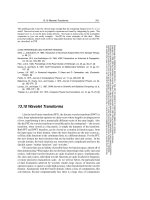
The test condition in Fig. 22 was the weak heat dissipation at the condenser. That is, the
cooling water was not circulated at the condenser in order to investigate only the normal
operating characteristic of the micro CPL by phase change of the working fluid. In the case
of the heat pipe with the mechanism of vapor-liquid phase change, the heat pipe shows
isothermal characteristics which transfer a lot of heat in small temperature difference
between the evaporator and the condenser. Therefore, the normal operating state could be
confirmed by measuring the temperature difference between the evaporator and the
condenser when small power is input to the evaporator. In Fig. 22, the micro CPL with
working fluid shows lower thermal resistance than the micro CPL without working fluid in
both cases of total length being 50 mm and 70 mm. This means that the fabricated micro
CPL in the present study operates normally through the operating mechanism of vapor-
liquid phase change. In the case of the total length of 50 mm, the micro CPL with working
fluid shows lower thermal resistance about half of that of the micro CPL without working
fluid. In the case of the total length of 70 mm, the micro CPL with working fluid shows
lower thermal resistance about a third of that of the micro CPL without working fluid.
This means that although the total length is increased from 50 mm to 70 mm, the micro
CPL with working fluid operates normally by vapor-liquid phase change. However, the
thermal resistance of the micro CPL increased when the total length was changed from 50
mm to 70 mm.
012345
0
5
10
15
20
25
Thermal Resistance (
o
C/W)
Input Power (W)
Micro CPL of 50mm length(without W/F)
Micro CPL of 50mm length(with W/F)
Micro CPL of 70mm length(without W/F)
Micro CPL of 70mm length(with W/F)
Fig. 22. Comparison of thermal resistance between the flat plate type micro CPL with
working fluid and the one without working fluid
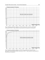
Fig. 23 shows the comparison results for the heat transfer rate between micro CPLs with
working fluid with total length of 50 mm and 70 mm. In Fig. 23, the input power was not the
maximum heat transfer rate; the heat transfer rate supplied to the evaporator was within the
wall temperature of 120 °C at the evaporator. In the figure, the heat at the condenser was
dissipated to the environment by the circulation of the cooling water. Through this
experiment test, it the amount of heat that can be transferred by the fabricated micro CPL
within the limited evaporator temperature could be investigated. The heat transfer rate of
7.5 W was obtained within the thermal resistance range of 6.8–19.9 °C/W in the case of the
total length of 50 mm. Meanwhile, the heat transfer rate of 6.1 W was obtained within the
thermal resistance range of 11.7–19.2 °C/W in the case of the total length of 70 mm. The
Heat Analysis and Thermodynamic Effects
290
thermal resistance increased and the heat transfer rate decreased when the total length was
increased from 50 mm to 70 mm. The operating mechanism of the flat plate micro CPL
developed in the present study was not known in detail. Furthermore, the amount of
working fluid and the structural design of the micro CPL were not optimized, therefore
further study is needed in the future.
012345678
4
8
12
16
20
24
Thermal Resistance (
o
C/W)
Input Power (W)
Micro CPL of 50mm length
Micro CPL of 70mm length
Fig. 23. Heat transfer rate according to increasing input power
4.4 Flow visualization of the micro CPL
Fig. 24 shows some images obtained by the visual inspection. They were captured on
arbitrary time while the micro CPL is operating. Figs. 24(b), (c), and (d) show the fluid flow
patterns in the path of the condenser. The fluid flow patterns in the micro CPL were very
active during the time the results of Fig. 24 are being obtained. Although any change in the
evaporator and the vapor line filled with vapor could not be seen with the naked eye, we
Fig. 24. Flow patterns at the condenser: (a) top view of the condenser; (b) (c) plug flow
patterns on low or middle heat flux (1–6 W), respectively; (d) annular flow pattern on high
heat flux (over 7 W)
Micro Capillary Pumped Loop for Electronic Cooling
291
could see the fluid flow phenomenon wherein the liquid and non-condensed vapor flow
together. An undesirable phenomenon wherein the vapor transported from the evaporator
was condensed on the top and bottom walls in the vapor line was observed with the naked
eye. The activity of two-phase flow patterns increases as the input power supplied to the
evaporator is increased. The fluid flow pattern was plug flow, wherein the vapor and liquid
bridge move in order, in low power (1–3 W) and middle power (4–6 W). The fluid flow
pattern changed from being plug flow to annular flow in high power (7–7.5 W). The plug
flow in the middle power range has larger velocity than that in the low power range. The
micro CPL shows the continuous circulating flow pattern over the entire power range. The
liquid drops created on the bottom and top walls at the vapor line should be removed since
they may increase the pressure drop in the vapor flow.
5. Commercialization of the MHP and micro CPL
The tubular type MHP, which was considered in chapter 3, can be used in any applications
and may also be packaged for high heat flux applications. The FPMHP, which was
fabricated by Al extrusion, was designed with consideration of capillary force. However, for
the purpose of the commercialization of the FPMHP, not only should the capillary force be
considered, but also the securing of the inner space. Furthermore, the fabrication cost and
fabrication process limit should also be considered. Fig. 24 shows a commercialized model
of the FPMHP, which is designed with consideration of the commercial viewpoint. It may be
applied to various fields like display, electronic package, automobile, and optic industry.
Flat plate micro CPL, which was considered in chapter 5, may be applied to slim mobile
electronic devices. The fabrication of a structure similar to design can be obtained. However,
for wider application, the fabrication of micro CPL using metal, instead of silicon and glass,
is needed. The cost and process of fabrication should be considered for commercialization as
well. Fig. 25 shows a micro CPL model fabricated by metal for commercialization. It is
composed of only two layers, compared to that considered in chapter 5 which has three
layers. The most important factor is reserving the inner space for fluid flow in the case of the
commercialized model shown in Fig. 25, which has thickness of less than 1 mm and is
composed of only two layers.
Fig. 25. FPMHP considering commercialization
Heat Analysis and Thermodynamic Effects
292
Fig. 26. Micro CPL considering commercialization
6. Conclusions
The characteristics, design, fabrication and thermal performance of MHPs and micro CPLs
were investigated.
Firstly, MHPs with polygonal cross section applicable to electronic units with thin structure
were manufactured and tested. The high productivity and simple manufacturing process
were also considered for future applications. The manufactured MHP showed good
isothermal property over the total length, and the temperature difference between the
evaporator and the condenser was about 4–6 °C. The inclination angle had a slight effect on
the thermal performance, and the thermal characteristic was stable from the top heating
mode to the bottom heating mode. The effect of the total pipe length on the thermal
performance of the triangular MHP was dominant. In the case of the triangular MHP, the
overall heat transfer coefficient was enhanced by about 92% when the total length was
decreased from 100 mm to 50 mm for 3 W of thermal load. The heat transfer limit of the
triangular MHP was 7 W, which is 1.6 times larger than the 4.5 W heat transfer limit of the
rectangular MHP. The heat transfer limit, which was the function of the operating
temperature, increased when the operating temperature was increased. The maximum heat
transfer limit of the triangular MHP was 10 W for the operating temperature of 90 °C. In the
present study, the heat transfer limit was 1.7–2.1 times larger than that of Moon (Moon et al.,
1999) for the operating temperature of 60–80 °C. The manufactured MHP in the present
study exhibited superior heat dissipation capacity and thus can be widely used in integrated
electronic units as a cooling module.
Secondly, the flat plate type micro CPL with thickness of 1.5 mm was designed, and its
fabrication technology was developed through the present study. The micro CPL was
designed to have an evaporator, a vapor line, two liquid lines, and a condenser in flat plate
shape, ensuring a large space for the vapor flow. In particular, the evaporator was designed
to have two-step grooves in order to secure the space for the vapor flow and prevent the
backflow of bubbles. The individual fabrication processes technologies for each plate of
Micro Capillary Pumped Loop for Electronic Cooling
293
silicon and glass were developed. Particularly, the bonding technology of the fill tube on the
glass top plate was completed by the fragment silicon on which the circular type metal
bands were deposited. The filling technology of the working fluid into the micro CPL under
vacuum condition was completed by the conventional method of filling after vacuuming.
Through the performance tests for the fabricated micro CPLs with total length of 50 mm and
70 mm, it was confirmed that micro CPLs operate normally through the phase-change heat
transfer of the vapor and liquid. The thermal resistance of the micro CPL increased and the
heat transfer rate decreased within the wall temperature of 120 °C at the evaporator when
the total length increased from 50 mm to 70 mm. Through the visual study, it was observed
that the fluid flow pattern of the micro CPL was plug flow in the low (1–3 W) and middle
(4–6 W) power, and annular flow in the high power (over 7 W). The velocity of the fluid
flow increased according to the input power. Further study on determining the operating
mechanism of the flat plate type micro CPL and optimizing the structural design is needed
in the future.
7. References
A. Faghri, "Heat Pipe Science and Technology," Talor & Francis, 1995
A. Hoelke, et al., “Analysis of the Heat Transfer Capacity of a Micromachined Loop Heat
Pipe,”
ASME 1999, Vol. 3, 1999, pp.53-60
B. R. Babin, et al., "Steady-State Modeling and Testing of a Micro Heat Pipe,"
ASME J. of Heat
Transfer
, Vol. 112, No. 3, August, pp. 595~601, 1990
D. Wu, et al., "Investigation of the Transient Characteristics of a Micro Heat Pipe,"
AIAA J.
Thermophysics Heat Transfer, 5(2), April, pp. 129~134, 1991
F. M. Gerner, "Flow Limitation in Micro Heat Pipes,"
AFSOR Final Report, No. F49620-88-6-
0053, Wright-Patterson, AFB, Dayton, OH, 1989
G. P. Peterson, “An Introduction to Heat Pipes: Modeling, Testing and Applications,”
Wiley:
New York, NY, 1994
H. Xie, et al., “The Use of Heat Pipes in the Cooling of Portables with High Power
Packages,”
Thermacore Co., Technical Note
J. Kirshberg, et al., “Cooling Effect of a MEMS Based Micro Capillary Pumped Loop for
Chip-Level Temperature Control,”
ASME 2000, MEMS Vol.2, 2000, pp.143-150
J. S. Suh, et al., “Friction in Micro-Channel Flows of a Liquid and Vapor in Trapezoidal and
Sinusoidal Grooves,”
Int. J. of Heat & Mass Transfer, Vol. 44, 2001, pp.3103-3109
K. S. Kim, S. H. Moon, C. G. Choi, “Cooling Characteristics of Miniature Heat Pipes with
Woven-Wired Wick,”
11th Int. Heat Pipe Conf., Japan, Sep. 1999
L. Meyer, et al., “A Silicon-Carbide Micro-Capillary Pumped Loop for Cooling High Power
Devices,
” 19th IEEE Semi-Therm Symp., 2003, pp.364-368
M. C. Zaghdoudi, et al., “Theoretical Investigation of Micro Heat Pipes Performance,”
10th
Int. Heat Pipe Conf.
, Germany, Sep. 21-25, F-9, 1997
R. Hopkins, et al., “Flat Miniature Heat Pipe with Micro Capillary Grooves,”
Transaction of
the ASME
, Vol. 121, pp. 102-109, 1999
S. H. Moon, G. Hwang, H. G. Yun, T. G. Choy, “Operation Performance of Miniature Heat
Pipe with Composite Wire Wick,”
IMAPS 2001, pp. 207-211, 2001
S. H. Moon, G. Hwang, H. G. Yun, “Improving Thermal Performance of Miniature Heat
Pipe for Notebook PC Cooling,”
Microelectronic Reliability, Vol.42, No.1, 2002
Heat Analysis and Thermodynamic Effects
294
S. H. Moon, et al., “An Experimental Study on The Performance Limitation of a Micro Heat
Pipe with Triangular cross-section,”
11th Int. Heat Pipe Conf., Japan, Sep. 1999
S. H. Moon, et al., “Heat Transport Performance of Micro Heat Pipe with Cross Section of
Polygon,
” IMAPAS 2002, Int. Symposium on Microelectronics, Session WP4, 2002
S. H. Moon, et al., “Manufacturing and Thermal Performance of the Flat Plate Micro Heat
Pipe,”
IMAPS ATW on Thermal Management for High Performance Computing
Telcom/Wireless
, 2002
T.P. Cotter, "Principles and Prospects for Micro Heat Pipes",
Proceedings of the 5th Int. Heat
Pipe Conference
, 1984.
14
The Investigation of Influence
Polyisobutilene Additions to Kerosene
at the Efficiency of Combustion
V.D. Gaponov
1
, V.K. Chvanov
1
, I.Y. Fatuev
1
, I.N. Borovik
2
, A.G. Vorobiev
2
,
A.A. Kozlov
2
, I.A. Lepeshinsky
2
, Istomin E.A.
2
and Reshetnikov V.A.
2
1
OAO “NPO Energomash”
2
Moscow Aviation institute (State Technical University)
Russia
1. Introduction
Liquid rocket engines reached high efficiency at presence. Next improvement of they
energetic, mass and reliabilities characteristics is labor-intensive and high expensive process.
It is famous, that addition of polymers to carbonhydogen fuels decrease substantially
hydraulic losses at the friction in pipelines and aggregates of engines. Fulfilled in “NPO
Energomash” the programme investigation influence of additions polyisobutilene to
kerosene at the hydraulic tests exploitated engines was showed, that the decrease of the
hydraulic losses may be more 20% [7]. The use of this effect lets or increase pressure in the
combustion chamber at constant heat intensivity of the turbine or to increase the resource of
the engine at the base decrease heat intensivity of turbine.
The question regarding influence addition at the combustion efficiency stated not clear. This
investigation for full-sized engines though doesn’t required fabrication new material part,
but is completed and expensive process analogically fire tests of the engine.
Most likely mechanism influence of addition at combustion efficiency may be pulverization
of liquid fuel. The program investigation of this mechanism was developed at department
202 of MAI [3]. This program included two steps. The first step was directed at obtaining
characteristics of pulverization one from mixed head liquid rocket engine of small thrust
MAI-202K, working at kerosene and gaseous oxygen. Characteristics of pulverization of the
mixing head at clean kerosene and kerosene with additions were diagnosed by dispersal of
drops, obtained at automatically measurement system. Method dispersal measurement was
based at change intensify projecting at the screen reflected from drops laser ray.
The second step consist fire tests of engine MAI-202 with seven swirl injectors mixing head
and oxygen curtain. Tests were fulfilled at the fire stand of department 202 MAI, at the same
regime of work, but at different fuels: clean kerosene and kerosene with additions 0.05-
0.01% polyisobutilen.
In the article detail materials are introduced about results as hydraulic, so and fire tests,
measured equipment, design of mixing head, characteristics of pipeline. Combustion
efficiency was obtained as ratio of experimental value mass flow complex β
exp
to
thermodynamic value mass flow complex β
t
.
Heat Analysis and Thermodynamic Effects
296
2. Composition and structure of test stand
Experimental investigation of influence 0.05% polyisobutilene additions to kerosene was
fulfilled at the test-bad № 72-2 department 202 MAI for fire tests liquid rocket engines of
small thrust (LRE STh) at ecological clean propellants [2]. Hydraulically pipe line of
kerosene is selection pipes from stainless steel of variable diameter (4-16mm) total length
8.12m. Pipe line connects kerosene tank with investigated mixing head and consists control
valve, filters (net 7 and 70 micro meters), sensors of mass flow, pressure and temperature
(Fig. 1).
Fig. 1. Kerosene feeding system.
Take into account fire danger of mixture drops of kerosene with oxygen, for the obtaining
characteristics of pulverization the special drops-trap was designed and fabricated. Scheme
of this drops-trap is showed at Fig. 2.
The Investigation of Influence Polyisobutilene
Additions to Kerosene at the Efficiency of Combustion
297
Fig. 2. Scheme of drops-trap.
Drops-trap consists from tube diameter 400mm, upper top with mounted kerosene pipe
with injector (or mixing head), two diameterally opposite orifices for registration quality of
pulverization, low lid with branch pipe drain of kerosene and system of forced extraction
mixture with fan in explosive-protected fulfillment.
Vertical position of drops-trap corresponds vertical position of tested engine and guarantees
the same influence of gravitation forces at the torch of pulverization. Photos of drops-trap
are presented at Fig. 3. Photos of working laser system during test presented at Fig. 4.
Heat Analysis and Thermodynamic Effects
298
Fig. 3. Photo of drops-trap.
Fig. 4. Laser ray goes through the spray.
The Investigation of Influence Polyisobutilene
Additions to Kerosene at the Efficiency of Combustion
299
System of distanced laser measurer guarantees registration diagram of dispersion of aerosol
cloud at the distance till 2 meters from measured volume. In result of mathematical
computing sizes and concentration parts are definite (fase-dispersia composition).Structure
scheme of measured system is presented at Fig. 5.
1 - bloc of laser radiators;
2 – control bloc of laser radiators;
3 - bloc of transfer optical system;
4 – bloc of accepted optical system;
5 –light dispersion screen;
6 –mask;
7 – filter;
8- digital camera;
9 – computer.
Fig. 5. Structure scheme of а base distanced laser measurer:
Bloc of transferred lenses 3 contains field diaphragm and, some times, collimator forming
probe-rays and sizes of measured volume. Bloc of entranced optics contains Furie-linses,
having focus-distance 50-100 cm and light diameter 10-20 cm.
Focus distance of lenses, entranced in collimator, is changed from 10mm till 20cm.Because of
small sizes of parts(2-10micron)and big distances(till 2m) diameter most information part of
spatial specter, in which about 90% energy dispersed radiation is consisted , is obtained
more 20 cm.
Therefore, in order to fix this specter directly at photo-matrix, it is necessary to fabricate it’s
specially, but it go to big expenditures. In order to fix this spatial specter by series digital
camera 8, in frequency plate bloc of entrance optics was mounted light dispersion screen 5,
which visualizes the spatial specter. In order don’t spoil matrix of camera 8 by direct laser
ray, behind screen 5 sometimes expediently to place mask 6, absorbed direct laser radiation.
Sometimes, in order to decrease light-dispersion between elements of screen 5, mask is
placed before screen. For decrease influence of background light before lenses of camera 8
may to place interference light-filter 7. For two lengths wave of laser radiation light-filter
may by changed or special to fabricate. The spatial specter, fixed by digital camera 8, goes in
computer 9, where with help of special software the sizes and concentrations parts of
Heat Analysis and Thermodynamic Effects
300
aerosol are calculated. Control of laser radiations is realized across computer 9 (for increase
of the mobility notebook is used).
Transferred bloc of measurer contains half-conductor laser 1(Fig. 6) (length wave 650 nm,
type of laser KLM-650/20) and field diaphragm 2mm,wich decrease diameter of laser ray,
tested measured volume with drops of pulwerizated.
Light, distributed in direct direction 4 and under small angles, put at Furie-linse 5, in focal
surface of which is placed screen 6.Focus distance of Furie-linse equal 500mm, light
diameter 200mm. Screen was fabricated from glass, mated with one side and thickness
3mm, sizes 300x300mm.
Fig. 6. Principle scheme of system for measurement distribution drops at sizes.
The distribution of light intensivity in focal surface of linse (part of indicatrisse,
corresponding small angle of dispersion) is fixed by digital camera 7 (Canon EOS 1000P).
Furie linse 5, screen 5 and digital camera 7 entrance in composition reception optoelectronic
bloc, intended for measurement characteristics dispersion of kerosene cloud in diapason of
measurement 1-10micron. For diapason of measurement 0.2-2micron in reception bloc are
introduced additional: digital camera8, fixed opposite dispersion, camera 9, fixed dispersed
light under straight angle, and camera10, fixed light , dispersed in direct direction, but at
angles more 100°(at angles, going out from limits of small angle dispersion).Montage of
cameras 8 and 10 under angles regarding main optical axis α and (180°- α) and lets use for
measurement aerosol sizes method asymmetric of indicatrisse of dispersion. This does more
simple the treatment of results. Registration of dispersed light by all cameras fulfilled
simultaneously. This reaches by use commutater 11 and control bench of photography 12.
Control of cameras 7-10 is realized across USB-divider13 and computer 14. It is possible and
hand regime control of cameras. Information entrances across USB- divider 13 in computer
14 fixed these cameras and is treated.
The Investigation of Influence Polyisobutilene
Additions to Kerosene at the Efficiency of Combustion
301
If diameter nozzle of model injector, used during test, equal 0.8mm, that quantity drops
with diameter less 2 micron will be not significant, therefore the use cameras 8, 9 and 10 in
test not certainly.
3. The investigation of influence polyisobutilene additions to kerosene at the
dispersion of pulverization
For the treatment obtained drops and calculation parameters of dispersion of aerosol cloud
the program is used, developed in MAI at department 201 and realized at the base packet
MATLAB (Fig. 7).
Fig. 7. Interface program calculation of parameters aerosol dispersion.
Laser device is montage at two controlled by altitude tables, placed at different sides from
drops-trap (Fig. 8). Axes of scanner ray go in orifices of drops-trap.
In order to separate factor influence of molecules polyisobutilene at the pulverization, the
cone of pulverization of single swirl injector with geometrical characteristic
()
2
3.2
nozzle in
ARr nr== and nozzle diameter 0.8 mm was analyzed. Distance from nozzle cut
off till surface of scanning consists 60 mm.
Estimation of quality of dispersion for common surface area defined by Sauter's diameter
parameter. Diameter Sauter is diameter of thermometric drop which has volume\surface area
coefficient equal middle volume\surface area coefficient calculated of whole drops in volume.
Heat Analysis and Thermodynamic Effects
302
Fig. 8. Laser device mount in the fire stand.
Results investigation pulverization of centrifugal injector are presented in Table 1.
Presence of
addition
Mass
flow
g/s
Pressure of
pressurizat
ion,аtm
Pressure
before
valve,аtm
Pressure
before
injector,
аtm
Δр
inj
аtm
Δр
pipe
line,
аtm
Diameter
Sauter’s,
micron
Without of
addition
4,45 4.5 4.8 3.83 0.97 0.7 5.199
Without of
addition
5.0 5.44 5.77 4.72 1.05 0.67 4.56
With
addition
4.2 12.0 4.6 3.55 1.05 8.4 3.48
With
addition
5.38 14.8 6.44 5.44 1.0 9.36 2.94
Table 1.
Analysis of obtained results lets to approve, that 0.05% addition in polyisobutilene in
kerosene to improve quality of pulverization ( at equal mass flow of kerosene), about this
show decrease of diameter Sauter approximately in 1.5 times. We may white better quality
of pulverization during fire tests, because by antypressure in combustion chamber quality of
pulverization will be better [5].
It is well known, that median diameter of drops during the pulverization of liquid by swirl
injector is obeying the dependence [6]:
()
0.6 0.1 0.7
47.8 Re
mc
dd A=∏
,
2
LLLc
d
ηρσ
∏=
,
The Investigation of Influence Polyisobutilene
Additions to Kerosene at the Efficiency of Combustion
303
Re
LecL
Wd
ρ
η
= ,
where
L
ρ
,
L
η
,
L
σ
- density, dynamic viscosity coefficient and surface tension of liquid, A -
geometrical characteristic of injector,
e
W - equivalent velocity of flow,
c
d - nozzle diameter
of injector. Then
0.1 0.5
mc LL
dd
ση
, so fineness of pulverization improve when viscosity and
surface tension are decrease in case if geometrical characteristic of injector and pressure
drop not change.
Therefore, there is interest of directly measurement of viscosity and surface tension of
kerosene with additions of polyisobutilene for physical interpretation of pulverization
process.
4. Investigation influence of polyisobutilene addition to kerosene at the
hydraulic resistance of pipe line
For normal kerosene the mass flow rate is 12 gr/sec for feed pressure 10 atm in filter/no
filter cases. For kerosene with polyisobutilene addition the mass flow is 4 gr/sec if filter
exist on the pipe line and 16 gr/sec if filter absent on the pipe line.
Result (Fig. 9) show that 7 micron filter increase hydraulic loss even if length of pipe line
is not big. If case using this kind of filters in LRE pipe lines the hydraulic loss will
be sizeable in the cooling jacket of combustion chamber. Without 7 micron filter the
hydraulic loss of pipe line increase. The influence of 70 micron filter on hydraulic loss not
defined.
Fig. 9. Feeding pressure/mass flow rate dependency.
Heat Analysis and Thermodynamic Effects
304
5. Design of LRE of small thrust for fire tests
Combustion efficiency of propellant in the combustion chamber depends not only from
quality pulverization of injector. It depends and from a lot of additional factors: mass flow
ratio, number of injectors and scheme its placement at mixing head, combustion chamber
pressure, system of inner cooling and others. It is clear, that for separation influence of
addition to kerosene it is necessary to fulfill two fire tests at the same engine and the same
regime parameters.
For realization fire tests with the use addition of polyisobutilene to kerosene in MAI was
developed engine MAI-200-7ОК at propellant gaseous oxygen and kerosene (see Fig. 10 -
Fig. 12) [3, 8, 9].
A small number of experiments and the difference in the initial parameters of the
experiments cannot define exact dependency of polyisobutilene additions on the quality of
the spray component.
To determine the effect of polyisobutilene additions on the quality of the spray component
is necessary to continue experimental work for a set of statistics.
Fig. 10. Drawing of mixing head. 1.top of head, 2.plate of fuel, 3.plate of oxygen,4.flange,
5.candle of ignition, 6. compression of candle, 7.connecting pipes for components, 8.bush of
candle, 9.compression of the bush.
Demountable head of engine was fulfilled at technology soldering of plates, bloc from witch
place in body-flange. Head has 6 bipropellant swirl injectors with inner stage of fuel and
outside open stage of oxidizer. Components go in any injector across two tangencies
channels. Ignition of mixture is realize by electrical discharge in the electrical candle, placed
in central part of the head. Candle is placed in open volume, in which oxidizer and fuel go
during tangential channel like for injectors. Control mass flow of kerosene in volume of
The Investigation of Influence Polyisobutilene
Additions to Kerosene at the Efficiency of Combustion
305
ignition is realized with help of bush with orifices given section. Candle works from
electrical high voltage discharger with frequency 200 Hz.
Fuel goes across connecting pipe in central collector and distributed on radial grooves to
tangential channels (Fig. 13).
Oxidizer goes in the head across connecting pipe, later goes across plate of fuel, enters in
central collector and distributed at radial grooves to tangential channels (Fig. 14).Part of
oxidizer from radial grooves at special orifices goes at inner (curtain) cooling.
Fig. 11. Model of mixing head.
Fig. 12. Photography of mixing head.
Heat Analysis and Thermodynamic Effects
306
Fig. 13. Plate of fuel. Red arrow - inlet of fluid.
Fig. 14. Plate of oxidizer. Red arrow - inlet of gas.
Mixing head connect with combustion chamber across compressed cupper ring. The
fighting of bolts at flange is fulfilled with help of dynamometer key, in order to except
unevenness compressed forces. Before fire tests the compressing of engine is fulfilled:
combustion chamber in critical area is condensed by flange with central rubber cone.
Flanges of head and condensed element are jammed by studs. During compressing the
compression of connection chamber with mixing head and placement of candle are
examined.
The Investigation of Influence Polyisobutilene
Additions to Kerosene at the Efficiency of Combustion
307
6. Investigation influence of polyisobutilene addition to kerosene at the
combustion efficiency kerosene - oxygen propellant
Fire tests were fulfilled at the combustion chamber with short nozzle part (Fig. 15). That
methodic of test lets to exam workability of own combustion chamber during long works
without the use high expenditure vacuum equipment.
In process of experiment mass flow complex
2
(,)
Smkc
f
mk pFm
β
==
(or C*) of engine
MAI-200-7ОК is defined for 2 cases:
• standard kerosene;
• kerosene with 0.05% polyisobutilene addition.
The value of
exppk theory
ϕβ β
= show the efficiency of chamber process.
Main measured values were: stable combustion chamber pressure and mass flow of oxidizer
and fuel.
Fig. 15. Engine at the working zone of test bench.
Combustion
chamber with
thermocouples
Entrance O
Entrance F
Candle of
ignition
Sensor of
pressure
Heat Analysis and Thermodynamic Effects
308
Tests of engine are fulfilled in two stage:
• tuned tests (duration < 0.5 sec);
• pass tests (duration < 5 sec) (Fig. 16);.
Results of pass tests are presented in Table 2.
Kerosene \
Parameter
о
m , gr/s
г
m , gr/s
m
k
к
p
, atm
Э
β
, sec
Т
β
, sec
p
k
ϕ
Without
addition
24,3 5,7 4,2 4,09 148 172 0,86
With
addition
26 6,8 3,8 4,14 146 169 0,86
Table 2. Base middle parameters of fire tests.
Fig. 16.
Photo of working thruster.
In Fig. 17 - Fig. 20 presented the result of tests. The calculation of theoretical value of mass
flow complex (C*) is fulfilled with help of program complex “Astra-M”. The low value of
mass flow complex (C*) because during test the combustion chamber pressure is 4.5 atm and
less then nominal value of engine (10 atm). The difference in efficiency of chamber pressure
depend on small diff of mass flow rate.
The Investigation of Influence Polyisobutilene
Additions to Kerosene at the Efficiency of Combustion
309
Fig. 17. Combustion chamber pressure.
Fig. 18.
Mass flow rate.
Heat Analysis and Thermodynamic Effects
310
Fig. 19.
Mass flow complex (C*).
Fig. 20. Efficiency of chamber pressure
p
k
ϕ
.
The Investigation of Influence Polyisobutilene
Additions to Kerosene at the Efficiency of Combustion
311
The result show that addition polyisobutilene to kerosene (0.05%) don’t influence at
combustion efficiency
p
k
ϕ
of propellant in limit mistake of measurements.
7. Conclusion
Completed the initial investigation of the effect 0.05% addition polyisobutilene to kerosene
at characteristics of pulverization and combustion efficiency of propellant kerosene +
gaseous oxygen is fulfilled. Fire tests were fulfilled at liquid rocket engine of small thrust
MAI-200-7ОК.
Estimation quality of pulverization of swirl injector at value Sauter diameter was shown ,
that addition improved on smallness of pulverization. A small number of experiments and
the difference in the initial parameters of the experiments cannot define exact dependency of
polyisobutilene additions on the quality of the spray component. To determine the effect of
polyisobutilene additions on the quality of the spray component is necessary to continue
experimental work for a set of statistics.
A significant effect of additions of polyisobutilene on hydraulic resistance of the fine-mesh
filter defined. Fine-meshed filter (mesh size 7mkm) gives a significant increase in hydraulic
losses even on a small length of line of the stand. Without the filter pressure drop line
decreased.
Effect of additions of polyisobutilene on the combustion effectively of the engine on
experimental mode not detected. Firing tests will be continued on different modes to proof
and get new results.
8. References
[1] Alemasov V.E., Dregalin A.F., Tishin A.P. Teorija raketnyh dvigatelej. – M.:
Mashinostroenie, 1989. – 464 p.
[2] Vorob'ev A. G., Borovik I. N., Hohlov A. N. i dr. Modernizacija ispytatel'nogo ognevogo
stenda dlja issledovanija rabochih processov v zhidkostnyh raketnyh dvigateljah
malyh tjag na jekologicheski chistyh komponentah topliva. Vestnik MAI, T. 14, №1,
2010.
[3] Kozlov A.A., Abashev V.M. Raschet i proektirovanie zhidkostnogoraketnogo dvigatelja
maloj tjagi. – M.: MAI.2003. – 36 p.
[4] Kozlov A.A., Borovik I.N., Vorob'ev A.G. Razrabotka programmy jeksperimental'nyh
issledovanij rabochego processa v kamere sgoranija ZhRD pri rabote na kerosine s
polimernymi prisadkami poliizobutilena i provedenie pervogo jetapa
jeksperimental'nyh issledovanij. Tehnicheskij otchet po Kontraktu № 30610 –
02020/ 980 – 09 – 187 mezhdu MAI i OAO NPO «Jenergomash» im. akademika
V.P. Glushko (2 jetap). Moskva, 2009.
[5] Kozlov A.A., Borovik I.N., Vorob'ev A.G. Tehnicheskij otchet po Kontraktu № 40440 –
02020/ 980 – 10 – 190 mezhdu MAI i OAO NPO «Jenergomash» im. akademika
V.P. Glushko (3 jetap). Moskva, 2010.
[6] Kudrjavcev V.M. Osnovy teorii i rascheta ZhRD. Moskva, «Vysshaja shkola», 1975.
Heat Analysis and Thermodynamic Effects
312
[7] Chvanov V.K., Fatuev I. Ju., Gaponov V.D., Sternin L. . Uluchshenie harakteristik raket-
nositelej pri dobavlenii k toplivu vysokomolekuljarnyh prisadok. Dvigatel', № 6
(42), 2005.
15
Synthesis of Novel Materials by
Laser Rapid Solidification
E. J. Liang, J. Zhang and M. J. Chao
Zhengzhou University
China
1. Introduction
High power lasers have been widely used in industry as well as in laboratory for materials
surface heat treatment, cladding, welding, cutting, thin film deposition by laser ablation and
so on (Bogue, 2010; Chao & Liang, 2004; Wang et al., 2008; Kruusing, 2004), but they are
seldom used in the synthesis of pure bulk materials. In recent years, we explored the
synthesis of pure bulk materials with a high power CO
2
laser (Liang et al., 2007; 2007; 2008;
2009; Zhang et al., 2010). It is shown that a variety of materials can be successfully
synthesized by laser rapid solidification (LRS). The materials synthesized by LRS exhibit
unique microstructures, superior properties which may not be realized by traditional
synthetic methods. Compared to the commonly used solid state reactions and wet chemical
routes which are usually severe time and energy wasting or require expensive precursors,
the laser synthetic technique provides a new and rapid method for the production of
materials, with which tens of grams of a sample can be produced in a few or tens of seconds.
In this paper we address the synthesis and characteristics of negative thermal expansion
materials and ionic conductive materials using LRS. Particular attention will be paid to the
unique microstructures, special or controlled phase formation and related superior
properties of the materials synthesized by LRS which may not be obtained by other
methods. The oriented crystalline growth dictated by heat transfer directions and the
particular phases formed at high temperatures in the molten pool and pressures induced
during the rapid solidification process will be discussed. Besides, many factors such as laser
power, scan speed and cooling environments are shown to affect the laser rapid
solidification rate and hence the pressures induced. With the help of experimental results,
the influence of these factors on the cooling rate, pressures induced and the phases of final
products are revealed.
2. Synthesis of negative thermal expansion materials by LRS
It is well known that the vast majority of materials expand on heating and contract on
cooling at widely different rates. This can cause a variety of problems in applications such as
delamination of layers or cracking of connections, temporary or permanent device failure
due to strains induced by expansion and contraction. Materials with opposite thermal
properties, namely contract on heating and expand on cooling are particularly desired to
facilitate the possibility to engineer materials with controllable overall negative, zero or