Heat Analysis and Thermodynamic Effects Part 12 pdf
Bạn đang xem bản rút gọn của tài liệu. Xem và tải ngay bản đầy đủ của tài liệu tại đây (1.33 MB, 30 trang )
Synthesis of Novel Materials by Laser Rapid Solidification
319
relative orderly arranged and densely packed blocks while that prepared by solid state
reactions consists of densely packed irregular shaped globose grains. The unique
microstructures of the samples produced in the laser synthetic route are attributed to the
relatively oriented crystalline growth governed by heat transfer directions.
Although both samples have similar density (98.5 % by LRS and 96.9% by SSR), the sample
prepared by LRS exhibits much superior conductivities (0.027, 0.079 and 0.134 Scm
-1
obtained at 600, 700 and 800
◦
C) to the sample prepared by solid state reactions (0.019, 0.034
and 0.041 Scm
-1
) (Zhang et al., 2010). Both XRD analysis and Raman spectroscopic study
suggest that the sample prepared by LRS crystallized in an orthorhombic and that by solid
state reactions in a monoclinic phase.
The samples La
0.8
Sr
0.2
Ga
0.83
Mg
0.17-x
Co
x
O
2.815
with high purity were also prepared by LRS. It is
shown that that Co-doped LSGMs exhibit unique spear-like or leaf-like microstructures (not
shown here) and superior oxide ion conductivity. The electrical conductivities of
La
0.8
Sr
0.2
Ga
0.83
Mg
0.085
Co
0.085
O
2.815
are measured to be 0.067, 0.124 and 0.202 Scm
−1
at 600, 700
and 800
◦
C, respectively, being much higher than those of the same composition by solid
state reactions (0.026, 0.065, 0.105 Scm
−1
).
The unique microstructures of the samples prepared by LRS should account mainly for their
superior electrical properties to those of the samples prepared by solid state reactions. The
relatively oriented and densely packed ridge-like (for LSGM) or leave-like (Co-doped
LSGM) grains with large and regular sizes in the samples by LRS greatly reduce the
scattering probabilities and thus increase the mean free path or the mean free time of charge
carriers during the drift motion.
It can be speculated from the appearances and SEM images that the starting materials
were sufficiently molten in the molten pool. Since the melting points of the raw materials
La
2
O
3
, SrCO
3
, Ga
2
O
3
and MgO are about 2315, 1497, 1740 and 2827
◦
C, respectively, the
temperature of the molten pool is expected to be above 2830
◦
C. The sufficiently high
temperature ensured sufficient melting of the raw materials and consequently rapid and
uniform reactions.
4. Conclusion
LRS has been used to the synthesis of NTE and oxide ion conductive materials for SOFCs.
Special characters of the LRS are the directed heat transfer and rapid solidification. The heat
transfer is mainly directed from the top surface to the bottom and also governed by the
moving direction of the laser beam as the laser energy is absorbed by the top layer of the
raw materials. The samples synthesized by LRS exhibits usually unique microstructures
which can be attributed to the relatively oriented crystalline growth governed by heat
transfer directions in the liquid droplet-like molten pool. It is also shown that a compressive
stress induced in the rapid solidification process can be large enough for the generation of
the γ phase ZrW
2
O
8
. Due to the rapid solidification from the molten pool, highly densely-
packed blocks of the samples can be easily achieved, in contrast to traditional solid state
reactions where sintering additives are usually required to achieve high density of samples.
The densely packed unique microstructures and perhaps also the spectial phases of the
electrolyte samples prepared by LRS make them superior in electrical properties to those of
the samples prepared by solid state reactions.
5. Acknowledgment
This work was supported by the National Science Foundation of China (No. 10974183)
Heat Analysis and Thermodynamic Effects
320
6. References
Chao, M. J. & Liang E. J. (2004). Effect of TiO
2
-doping on the microstructure and the wear
properties of laser-clad nickel-based coatings, Surf. Coat. Techn. Vol. 179, No. 2-3,
(Febrary, 2004), pp. 265-271, ISSN 0257-8972
Bogue, R. (2010). Fifty years of the laser: its role in material processing, Assembly Automation,
Vol. 30, No. 4, (April, 2010), pp. 317-322, ISSN 0144-5154
Kruusing A, Underwater and water-assisted laser processing:Part 1—general features,
steam cleaning and shock processing, Optics and Lasers in Engineering, Vol. 41, No.
2, (Febrary, 2004) pp. 307-327, ISSN: 0143-8166
Liang, E.J.; Wu, T. A.; Yuan, B.; Chao, M. J. & Zhang, W. F. Synthesis, microstructure and
phase control of zirconium tungstate with a CO2 laser, J Phys D Appl Phys.Vol. 40, No.
10, (May, 2007), pp. 3219-3223, ISSN: 0022-3727; Liang, E. J.; Wang, S. H.; Wu, T. A.;
Chao, M. J.; Yuan, B. & Zhang, W. F. Raman spectroscopic study on structure, phase
transition and restoration of zirconium tungstate blocks synthesized with a CO
2
laser,
J Raman Spectrosc,Vol. 38, No. 9, (September, 2007) , pp. 1186-1192, ISSN: 0377-0486;
Liang, E. J.; Wang, J. P.; Xu, E. M.; Du, Z. Y. & Chao, M .J. Synthesis of hafnium
tungstate by a CO
2
laser and its microstructure and Raman spectroscopic study, J
Raman Spectrosc., Vol 39, No. 7, (July, 2008), pp. 887-892.; Liang, E. J.; Huo, H. L.;
Wang, Z.; Chao, M .J. & Wang, J. P. Rapid synthesis of A
2
(MoO
4
)
3
(A=Y
3+
and La
3+
)
with a CO
2
laser, Solid State Sci., Vol. 11, No. 1, (January,2009), pp. 139-143, ISSN:
1293-2558 ; Liang, E. J.; Huo, H. L. & Wang, J. P. Effect of water species on the phonon
modes in orthorhombic Y
2
(MoO
4
)
3
revealed by Raman spectroscopy, J Phys Chem C,
Vol. 112, No. 16, (April, 2008), pp. 6577-6581, ISSN:1932-7447; Liang, E. J. Negative
Thermal Expansion Materials and Their Applications : A Survey of Recent Patents,
Recent Patents on Mat Sci.,Vol. 3, No. 2, (May, 2010), pp. 106-128, ISSN:1874-4648
Mary, T. A.; Evans, J. S. O.; Vogt, T. & Sleight, A. W. Negative thermal expansion from 0.3 to 1050
Kelvin in ZrW2O8, Science, Vol. 272, No. 5258, (April, 1996), pp. 90-92, ISSN: 0036-8075
Mittal, R.; Chaplot, S. L.; Kolesnikov, A. I.; Loong, C. K. & Mary, T. A. Inelastic neutron
scattering and lattice dynamical calculations of negative thermal expansion in
ZrW
2
O
8
, Phys. Rev. B, Vol.68 No. 5, (August, 2003), pp. 054302, ISSN: 1098-0121
Perottoni, C. A. & da Jornada J A. H.,Pressure induced amorphization and negative thermal
expansion in ZrW
2
O
8
, Science, Vol. 280, No. 5365, (May, 1998), pp. 886-889, ISSN:
0036-8075
Ravindran, T. R.; Arora. A. K. & Mary, T A. High-pressure Raman spectroscopic study of
zirconium tungstate, J. Phys: Cond. Matter, Vol 13, No. 50, (December, 2001), pp.
11573-11588, ISSN: 0953-8984
Wang, D. S.; Liang, E. J.; Chao, M. J. & Yuan, B. Investigation on the Microstructure and
Cracking Susceptibility of Laser-Clad V2O5/NiCrBSiC Coatings, Surf. Coat. Techn.
Vol. 202, No. 8. (January, 2008), pp. 1371-1378, ISSN 0257-8972
Yuan, C. ; Liang, Y. ; Wang, J. P. & Liang, E. J. Rapid Synthesis and Raman Spectra of
Negative Thermal Expansion Material Yttrium Tungstate, J Chin Ceram Soc., Vol 37,
No. 5, (May, 2009), pp. 726-732, ISSN: 0454-5648
Zhang, J.; Liang, E. J. & Zhang, X. H. Rapid synthesis of La
0.9
Sr
0.1
Ga
0.8
Mg
0.2
O
3−δ
electrolyte by
a CO2 laser and its electric properties for intermediate temperature solid state
oxide fuel cells, J. Power Sources, Vol. 195, No. 19, (October, 2010), 195: 6758-6763,
ISSN:0378-7753
16
Problem of Materials for
Electromagnetic Launchers
Gennady Shvetsov and Sergey Stankevich
Lavrentyev Institute of Hydrodynamics Novosibirsk
Russia
1. Introduction
During the last twenty years, considerable attention of researchers working in the areas of
pulsed power, plasma physics, and high-velocity acceleration of solids has been given to
electromagnetic methods of accelerating solids. These issues were the subject of more than
twenty international conferences in the U.S. and European countries. Papers on this topic
occupy an important place in the programs of international conferences on pulsed power,
plasma physics, megagauss magnetic field generation, etc. The increased interest of the
world scientific community in problems of electromagnetic acceleration of solids to high
velocities is due to the high scientific and practical importance of high-velocity impact
research. Accelerators of solids are used to study the equations of state for solids under
extreme conditions, simulate the effects of meteorite impact on spacecraft, investigate
problems related to missile defense, test various artillery systems and weapons, etc.
Information on the development and current status of research on electromagnetic methods
for high-velocity acceleration of solids in the United States, Russia, France, Germany, Greate
Britain, China and other country can be found in reviews (Fair, 2005, 2007; Shvetsov et al.,
2001, 2003, 2007; Lehmann, 2003; Haugh & Gilbert, 2003; Wang, 2003).
For high-velocity accelerators of solids, the most important are two characteristics and
answers to the following two questions: 1) what absolute velocities can be achieved in a
particular type of launcher for a body of a given mass? and 2) what is the service life of the
launcher? An analysis of existing theoretical concepts and available experimental data has
shown that the most severe limitations in attaining high velocities and providing acceptable
service life of electromagnetic launchers are thermal limitations due to the circuit current. A
number of crisis (critical) phenomena and processes have been found that disrupt the
normal mode of accelerator operation and lead to the destruction of the accelerated body or
accelerator or to the termination of the acceleration.
In electromagnetic plasma armature railguns, one of the main factors limiting the projectile
velocity is the erosion of rails and insulators, leading to an increase in the mass accelerated
in the launchers, an increase in the density of the gas moving in the channel, an increase in
viscous friction, and a decrease in the dielectric strength of the railgun channel, which can
cause a secondary breakdown in the channel with the formation of a new arc and setting an
additional mass of gas in motion, etc. The main factor responsible for the intense erosion of
materials is their heating by the radiation from the plasma armature to temperatures above
the melting and vaporization temperatures of the materials.
Heat Analysis and Thermodynamic Effects
322
In coil guns, Joule heating by the current results in a reduction in the mechanical strength of
projectiles up to its complete loss during melting. Magnetic forces can lead to deformation
and fracture of the inductor and accelerated body and other phenomena.
The main problem limiting the attainment of high velocities in metal armature railguns is
the problem of preserving the sliding metallic contact at high velocities. An increase in the
current density near the rear surface of the armature, due mainly to the velocity skin effect,
leads to rapid heating, melting, and vaporization of the armature near the contact
boundary. The development of these processes result in a rapid transition to an arc contact
mode, enhancement of erosion processes, reduction or termination of the acceleration, and
destruction of the barrel and accelerated body (Barber et al., 2003).
One of the necessary conditions for the implementation of crisis-free acceleration is the
requirement that the elements of the launcher and accelerated body be heated below the
melting point throughout the acceleration. The heating limitation condition implies
restrictions on the maximum value of the magnetic field strength and the maximum linear
current density in electromagnetic launchers and to a limitation on the velocity.
In the chapter, the velocity to which a solid of a given mass can be accelerated at a certain
distance provided that, during acceleration, the temperature of the rails and accelerated
body does not exceed certain values critical for the type of launcher and material used is
considered the ultimate velocity in terms of the heating conditions or simply the ultimate
velocity.
An analysis has shown that the ultimate velocities can be substantially increased by using
composite conductors with controllable thermal properties and by optimizing the shape of
the current pulse. Thus, the problem of materials and thermal limitations for
electromagnetic launchers of solids is central to the study of their potential.
This chapter presents the results of studies of thermal limitations in attaining high velocities
in electromagnetic launchers; analyzes the possibility of increasing the ultimate (in terms of
heating conditions) velocities of accelerated solids in subcritical modes of operation of
electromagnetic launchers of various types (plasma armature railguns, induction and rail
accelerators of conducting solids) taking into account the limitations imposed on the heating
of the launcher and accelerated body during acceleration; and investigates various ways to
increase the ultimate kinematic characteristics of launchers through the use of composite
conductors of various structures and with various electrothermal properties as current-
carrying elements.
2. Problems of materials in plasma-armature railguns
In analyzing various physical factors that limit the performance of plasma-armature
railguns, it is convenient to use the concept of the critical current density
*
/Ib(
*
I is the
current in the circuit,
b is the width of the electrodes) above which these factors begin to
manifest themselves. This was apparently first noted in (Barber, 1972). Estimates show
(Barber, 1972; Shvetsov et al., 1987) that the smallest value of
*
/Ib is obtained from the
condition that the current flowing in the circuit must not lead to melting of the electrodes
and, consequently, to high erosion.
Investigation of the ultimate capabilities of the erosion-free operation of plasma-armature
railgun requires, first of all, knowledge of the plasma armature, railgun, and power supply
characteristics necessary for this operation regime. As shown by experimental studies
(Hawke & Scudder, 1980; Shvetsov et al., 1987), plasma-armature properties (length
l
p
,
Problem of Materials for Electromagnetic Launchers
323
average density ρ
p
, impedance r
p
) differ only slightly from some typical values r
p
~ 1
mohm,
l
p
~(510)b, and ρ
p
~ 1030 kg/m
3
in both different experimental setups and in the
acceleration process. Thus, for a given accelerator channel cross section and a given
projectile mass, the only parameters that can be varied to control the development or
slowing of erosion processes are the linear current density in the accelerator
I/b and the
thermophysical properties of the electrode material.
In analysis of the possibilities of increasing
*
/Ib, the question naturally arises as to
whether composite materials can be used for this purpose. Prerequisites for increasing
*
/Ibare the well-known fact of high erosion resistance of composite materials in high-
current switches (in 1.5-3 times higher the resistance of tungsten) and the assumption that in
a railgun, the plasma armature interacts with the electrodes in the same way as in high-
current switches (Jackson et al., 1986). A number of papers have reported experiments with
electrodes coated with high-melting materials such as W-Cu, W/Re-Cu, Mo-Cu, etc.
(Harding et al., 1986; Shrader et al., 1986; Vrabel et al., 1991; Shvetsov, Anisimov et al., 1992).
It has been noted that the coated copper electrodes (W-Cu, W/Re-Cu) offer advantages over
uncoated ones for use in rail launchers under the same conditions.
Fig. 1. Schematic diagram of the plasma-armature launcher of solids.
1 – power supply, 2 –
electrodes, 3 – plasma armature, 4 –projectile, 5 – switch.
We will analyze the possibilities of increasing the critical current density by using composite
electrodes in conventional plasma-armature railguns. A schematic diagram of a plasma
armature launcher of dielectric solids is shown in Figure 1, where 1 is the current source, 2
are electrodes, 3 is the plasma armature, 4 is the projectile, 5 is the switch, l
p
is the length of
the plasma armature,
b is the electrode width, and h is the distance between the electrodes.
When the switch 5 is closed, a current starts to flow in the circuit, producing an
electromagnetic force which accelerates the plasma armature and the projectile.
We will assume that changes in the electrode temperature are only due to the effect of the
heat flux from the plasma. As shown in (Shvetsov et al. 1987), if the temperature change due
to Joule heating is neglected, the error in determining the surface temperature is usually not
more than a few percents. The problem of determining the temperature in some local
neighborhood of a point
x
0
on the electrode surface can be regarded as the problem of
heating of a half-space z > 0 which generally has inhomogeneous thermophysical properties
by a heat flux
q acting for a time
0
()tx equal to the time during which the plasma armature
passes over the point
x
0
. This problem reduces to solving the heat-conduction equation with
a given initial temperature distribution and boundary conditions:
div(
g
rad )
T
ckT
t
x
y
z
1
0
x
0
b
I
3
4
2
l
p
V
5
h
Heat Analysis and Thermodynamic Effects
324
00 0
(,,, ( ))
Txyzt t x T (1)
000 00 00
0
(), , () () ()
z
z
T
kqtTTtxttxtx
z
where in the general case density
, heat capacity с, and thermal conductivity k may be
functions of х, у, and z depending on temperature T. T
0
. is the initial temperature,
00
()tx
is
the time of arrival of plasma armature to the point x
0
.
Following (Powell, 1984; Shvetsov et al., 1987) let us consider that the armature moves as а
solid body with constant mass, length l, and electric resistance r. Neglect the variation in the
internal thermal energy of plasma armature and assume that all energy dissipating in it
uniformly releases through the surface limiting the volume occupied by plasma. In this case,
all released energy is absorbed in the channel of the railgun as if the release had happened
in а vacuum.
These assumptions make it possible to establish а simple connection between the total
current I through plasma armature and the intensity of heat flux q from its surface:
2
p
rI
q
S
, (2)
where S is the area of plasma armature surface.
The dynamics of plasma armature and the projectile is determined by integrating the
equations of motion:
2
,
2
dV dL
IV
dt m dt
(3)
where
is the inductance per unit-length of railgun channel, т is the sum of mass of plasma
and projectile, and V is projectile velocity.
The critical current density is determined under the condition that the temperature at any
point
0
,xy on the electrode surface ( 0
z ) during the acceleration does not exceed the
critical temperature
*
T of the electrode material (the melting temperature for homogeneous
materials or the melting or evaporation temperatures for one of the components of
composite material).
Dependences of
the current density on time or the distance L traveled by the plasma
armature can be obtained by simultaneously solving equations (1)–(3).
A similarity analysis for the thermal problem (1) shows that the maximum temperature
max
()TK of a homogeneous electrode and a composite electrode consisting of a mixture of
fairly small particles depends only on the magnitude of the thermal action
K
q
t . The
magnitude of the thermal action
*
K at which the electrode surface reaches the critical
temperature
**
max
()
TKT depends only on the thermophysical properties of the electrode
material and can be regarded as a characteristic of the heat resistance of the material heated
by a pulsed heat flux (Shvetsov & Stankevich, 1995).
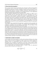
The maximum projectile velocity in plasma-armature railguns subject to the electrode
heating constraint is achieved when the shape of the current pulse provides a constant
thermal action at each point of the electrode surface and the magnitude of this action is
Problem of Materials for Electromagnetic Launchers
325
equal to the heat resistance of the electrode material. It is established that the dependences
of the critical current density and the ultimate projectile velocity on the traveled distance
*
()/, ()IL bVL for a railgun accelerator with electrodes made of an arbitrary material X are
linked to the corresponding dependences for the same accelerator with copper electrodes by
the relations
**
Cu
Cu
() ()
, ( ) ( )
X
X
IL IL
VL V L
bb
(4)
where the coefficient
23
**
Cu Cu
//
XX
KK
characterizes the relative heat resistance
of the material X with respect to the heat resistance of copper.
Fig. 2. Electrode structures. a) homogeneous electrode, b) coated electrode, c) multilayer
electrode with vertical layers, d) composite electrode consisting of a mixture of powders.
Сu Mo W Al Ta Re Cr Fe Ni
1.0 1.17 1.38 0.55 0.99 0.99 0.87 0.69 0.78
Table 1. Homogeneous metals
An analysis was made of the heat resistance and critical current density for electrodes of
various structures: a homogeneous electrode (Fig. 2, a), an electrode with a high-melting
coating (Fig. 2, b), an electrode with vertical layers of different metals (Fig. 2, c), and a
composite electrode consisting of a mixture of particles (Fig. 2, d).
Calculations of the coefficient of relative heat resistance of homogeneous electrodes of
metals such as W, Mo, Re, Ta, Cr, Ni, Fe, and Al showed that only tungsten and
molybdenum electrodes can compete with copper (
W
= 1.38,
Mo
= 1.17), and for other
metals 1
(Table 1).
An increase in the heat resistance of electrodes coated with a high-melting material
(Fig. 2, b) is possible if the thermal conductivity of the base material is higher than the
coating thermal conductivity and the heating rate of the base at a given heat flux is lower
than that of the coating. The maximum increase in heat resistance is achieved at an optimal
coating thickness at which the temperatures of the surface and the interface between the
materials simultaneously reach the values critical to the coating and base materials. The
optimum coating thickness depends on the heat flux and the duration of heat pulse;
therefore, to maintain the highest possible linear current density for a given pair of
materials, the coating thickness along the electrode should decrease according to a definite
law. The results of calculations of the relative heat resistance of copper electrodes coated
with various metals are presented in Table 2.
Heat Analysis and Thermodynamic Effects
326
W-Cu Ta-Cu Mo-Cu Re-Cu Cr-Cu Os-Cu
1
1.443 1.188 1.299 1.197 1.124 1.312
2
1.628 1.358 1.445 1.344 1.202 1.487
Table 2. Coated electrodes
The calculations were performed for two cases: in the first, it was assumed that during the
time of passage of the plasma armature, both materials remain in the solid phase (
1
), and in
the second case, melting of the base to a depth equal to the coating thickness (
2
) was
allowed. One can see that with the use of copper electrodes with an optimized thickness of
the tungsten coating, the heat resistance coefficient (and the maximum velocity) increases to
a value
W/Cu
1.45 under the maximum heating to the melting temperature, and to a
value
W/Cu
1.68 in the case where during the travel time of the thermal pulse, the copper
base is melted to a depth equal to the coating thickness and the surface tungsten layer
remains in the solid phase.
Analysis of the problem of heating of electrodes with vertical layers (Fig. 2, c) and composite
electrodes consisting of a mixture of particles (Fig. 2, d) by a heat flux pulse shows that for
electrodes of this type, the heat resistance cannot be increased if the maximum temperature
of the components does not exceed the melting temperature. However, if we assume that
during melting of one of the materials, the matrix consisting of the higher-melting material
remaining solid prevents the immediate removal of the melt from the electrode surface,
then, for such structures, the critical temperature will be the melting temperature of the
material forming the matrix or the evaporation temperature of the lower-melting material.
The heat resistance and the relative heat resistance coefficient was calculated for a number
of combinations of metals with various volume contents
and 1-
by numerically solving
the thermal problem (1) of heating of two-component composite materials with infinitely
small sizes of the components. Temperature dependences of the volumetric heat capacity
and thermal conductivity of composites and the latent heat of melting for the lower-melting
material were taken into account. The results of some calculations are given in Table 3. The
upper and lower values correspond to the maximum and minimum estimates of the thermal
conductivity of the composite.
Re-Cu Mo-Cu W-Cu Ta-Cu W-Mo W-Re
0.25
1.792
1.417
1.825
1.675
1.829
1.720
1.781
1.504
1.428
1.426
1.183
1.126
0.5
1.543
1.160
1.622
1.456
1.632
1.509
1.528
1.237
1.416
1.413
1.264
1.182
0.75
1.253
0.992
1.399
1.288
1.420
1.339
1.241
1.047
1.402
1.400
1.330
1.263
Table 3. Composite electrodes consisting of a mixture of powders
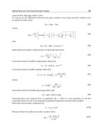
Figure 3 shows curves of
()VL (Fig. 3,a) and
*
()ILb (Fig. 3, b) for copper electrodes
obtained for a inductance per unit-length of railgun channel
= 0.3 H/m, plasma-
armature resistance r = 10
-3
ohm, a total mass of the projectile and plasma of 1 g, and a
channel cross-section of
11
cm. Curves 1-3 correspond to plasma armatures 5, 10, and 15
cm long.
Problem of Materials for Electromagnetic Launchers
327
Fig. 3. Velocity (a) and critical current density (b) vs. plasma piston position in the railgun
channel for copper electrodes. The numbers 1, 2, and 3 correspond to plasma length equal
5, 10, 15 cm.
Using electrodes with heat resistance twice the heat resistance of copper can lead to a factor of
two increase in the critical current density and velocity, which (as seen from the figure and
scale rations (4)) provides projectile velocities of 3-4 km/sec over an acceleration distance of 1
m and velocities of 5-7 km/sec over an acceleration distance of 2 m in the regime without
significant erosion of the electrodes. It can be concluded that the use of composite materials is
promising for achieving high velocities in plasma-armature railgun accelerators of solids.
3. Ultimate kinematic characteristics of conducting solids accelerated by
magnetic field
A factor limiting the attainment of high velocities during acceleration of conducting
projectiles by a magnetic field is the Joule heating of conductors to temperatures above the
melting point of the material. This can lead to loss of the mechanical strength of the
conductors, change in their shape, and, ultimately, failure. The requirement that the
conductors should not melt during acceleration imposes restrictions on the maximum
permissible amplitudes of the accelerating magnetic fields, thus limiting the maximum
velocity to which a conductor of given mass can be accelerated over a specified acceleration
distance (Shvetsov & Stankevich, 1992).
3.1 Formulation
To estimate the limits of the induction acceleration method, it is sufficient to consider the
problem of the ultimate (in terms of the heating conditions) kinematic characteristics of
infinite conducting flat sheets (Fig. 4) accelerated by magnetic pressure in the absence of
resistance. In this section, we consider the acceleration of homogeneous sheets (Fig. 4, a),
multilayer sheets (Fig. 4, b), and sheets containing a layer of composite material with
electrothermal properties varying across the layer thickness (Fig. 4, c).
At the initial time (t = 0), the velocity of the sheet V = 0, its temperature is T
0,
and a magnetic
field is absent in the sheet. In general, the electrothermal properties of the sheet (electrical
conductivity
, density
, specific heat c, and thermal conductivity k) can depend on the x
coordinate of the temperature T. For magnetic fields typical of induction accelerators, the
magnetic permeability
of materials will be equal to the magnetic permeability of vacuum
Heat Analysis and Thermodynamic Effects
328
µ
0
. Heat transfer between the sheet and the surrounding medium and the compressibility of
the sheet are neglected. We assume that the change in the internal thermal energy of the
sheet is determined by Joule heating and heat transfer.
Fig. 4. Structure of accelerated sheets.
In Cartesian coordinates attached to the sheet (the boundaries of the sheet correspond to the
planes x = 0 and x = d ), the distributions of the magnetic field
(,)Hxtand temperature
(,)Txtin the sheet depend only on the x coordinate and time t, and are described by the
equations of magnetic field diffusion and heat conduction with the initial and boundary
conditions:
11
HH
txx
(5)
2
1
TTH
ck
txx x
(6)
00
00 0
0
0, , , 0, 0
tt x xd
xxd
TT
HTTHHtH
xx
.
The time dependence of the magnetic field is assumed to be known and given by the
relation
0a0
() ()Ht Hh
, where
0
/tt (
0
t is a characteristic time).
For sheets consisting of several layers of materials with different electrothermal properties,
it is assumed that at the internal boundaries between the layers, where the properties of the
medium undergo a discontinuity, the continuity of the magnetic, electrical, and thermal
fields is preserved.
The velocity of the sheet V and the distance L traveled by it are determined by integrating
the equations of motion:
2
00
()
,
2
Ht
dV dL
M
V
dt dt
(7)
where
0
d
M
dx is the mass of the sheet per unit area of its surface (d is the sheet
thickness).
Problem of Materials for Electromagnetic Launchers
329
The heating constraint is given by the requirement that during acceleration of the sheet at a
given distance
L, the heating of any component of the sheet materials be not higher than its
melting temperature. Under this constraint and for a given function
0
()
h , the maximum
velocity of the sheet of given structure in the general case is determined by solving the
optimization problem consisting of choosing the maximum allowable (in terms of the
heating conditions) values of the magnetic field amplitude
H
a
and the acceleration time
0
t
that ensure the achievement of the maximum velocity over a given acceleration distance.
Similarity analysis for system (5) - (7) shows that for a sheet of arbitrary structure, it is
sufficient to determine the maximum velocity as a function of the sheet mass
(,)VML or
thickness
(,)VdL for any one acceleration distance L. For any other distance
L
,
these
functions can be found using the relation:
1/3
(,)(,), ,(,)(,), ,
L
VMLaVMLMaMVdLaVdLdada
L
(8)
3.2 Homogeneous sheets
For a homogeneous "thin" sheet (in this case, the acceleration time is much longer than the
time of magnetic field penetration into the sheet), direct integration of equations (5)-(7) gives
(Knoepfel, 1970)
0
0
2
2
J
VM
, (9)
where
m
0
2
0
tT
T
Jjdt cdT
is the current integral. In this case, the ultimate velocity of the
sheet does not depend on the magnetic field pulse shape
0
()Ht and the acceleration
distance and are determined only by the electrothermal properties of the sheet material and
the sheet mass per unit area or the sheet thickness.
For "thick" sheets (in this case, the time of magnetic field penetration into the sheet is much
greater than the acceleration time), the ultimate velocity in terms of the heating conditions
can be determined from the asymptotic relation (Shvetsov & Stankevich, 1994)
m
L
VQ
M
where
m
Q is the change in the thermal energy density of the sheet material under heating
to the melting temperature and
ψ is a coefficient which depends on the form of the function
0
()h
. If the magnetic field increases monotonically with time during the acceleration,
ψ = 1.1-1.2.
Figure 5 shows the results of numerical calculations of the dependence
(,)VML (curve 1) and
the asymptotic dependences
0
()VM and (,)
VML (curves 2 and 3 for the approximations of
“thin” and “thick” sheets, respectively) for a copper sheet,
L = 1 m, and a linearly increasing
magnetic field. The dependence
(,)VML is characterized by a velocity maximum which is
reached for a certain mass or thickness of the sheet. The maximum velocity and the optimum
mass depend weakly on the magnetic field pulse shape and are determined mainly by the
electrothermal properties of the material and the acceleration distance.
Heat Analysis and Thermodynamic Effects
330
Fig. 5. Dependence
V(M) (curve 1) for L = 1 m. Curve 2 and curve 3 are asymptotic
dependences obtained in the approximations of "thin" and "thick" sheets, respectively.
Figure 6,
a shows curves of the ultimate velocity versus sheet mass for Cu, W, Ti, Be, Fe, Mo,
Ag, Au, and Fig. 6,
b shows curves of the ultimate velocity versus sheet thickness for the
same materials. It is seen that from the point of view of providing the maximum velocity,
different materials can be optimal, depending on the given mass or required thickness of the
sheet.
A characteristic feature of the dependences
(,),(,)VML VdL (Fig. 6 a, b) is the presence of a
velocity maximum which is reached for a certain sheet thickness
opt
()dL or linear mass
otp
()
M
L that are optimal for each material. A decrease in the maximum velocity of the
sheets for
opt
MM is related to the localization of the region of maximum heating near the
sheet surface, where most of the current flows because of the time of field diffusion is much
greater than the time of acceleration of the sheet.
Fig. 6. Ultimate velocities vs. sheet mass (
a) and vs. sheet thickness (b), for L = 1 m
3.3 Multilayer sheets
In some papers (Karpova et al.,1990; Shvetsov & Stankevich, 1992, Zaidel’ , 1999), it was
noted that the use of heterogeneous conductors with electrical conductivity discreet or
continuously increasing with distance from the surface of the sheet can decrease their local
heating considerably.
Problem of Materials for Electromagnetic Launchers
331
In this subsection, we analyze the possibility of increasing the ultimate velocity of solids
accelerated by a magnetic field by using multilayer conducting sheets consisting of several
layers of materials with different electrothermal properties (Fig. 4,
b).
A simple analytical method for optimizing the sheet structure can be obtained if we assume
that the electrical properties of materials does not depend on temperature, neglect the
thermal conductivity of materials, and consider steady-state solutions of equations (5) - (7)
that correspond to the acceleration of sheets in an exponentially growing magnetic field
0
()he
.
An analysis has shown that for a given set of layer materials, the optimal structure (the
sequence of layer materials and thicknesses) is the one in which the melting temperature in
each layer is reached simultaneously by the time the sheet has traveled a given distance.
Solving equations (5) and (6) under the above assumptions, we obtain:
22
1
1
1
cth 1
ii
iii
ii
q
hhq
q
, (10)
1
111
cth( )
ln
cth( ) /
ii
i
ii iii
hq
hq
, (11)
where
m0 11m10
()/()
iiii
qcTT cTT
,
1
/
ii
dd
, h
i
is a dimensionless magnetic field,
and
2
0011
/tx
is an invariant parameter. In expressions (10) and (11), we set
1
1h ,
2, ,iN, where N is the specified number of layers. In this case, as can be seen from (10),
the sequence of layer materials should be chosen to reduce the values
m
/Q
in the
direction of magnetic field diffusion.
Using the heating constraint and the equation of motion (7) and taking into account the
similarity relations (8), we have:
1/3
2
01
m1
()
2()
L
Q
V
(12)
1/3
2
2
01 m1
4( ) ( )
()
()
L
d
Q
(13)
where
2
() (cth()/ )
N
h
,
N
h is the dimensionless magnetic field on the inner surface
(x = 0) of the multilayer sheet calculated by expression (10),
2
1
N
i
i
, and
is the
average density of the multilayer sheet.
Figure 7 shows curves of the ultimate velocity versus linear mass of multilayer sheets
calculated using analytical relations for an acceleration distance of 1 m (the sequence of
materials is indicated in the figure).
It can be seen that the use of multilayer sheets allows a considerable increase in the ultimate
velocity in terms of the heating conditions, compared to homogeneous sheets.
Heat Analysis and Thermodynamic Effects
332
Fig. 7. Ultimate velocity versus mass of multilayer sheets for some sequences of layer
material (indicated in the figure).
3.4 Sheets with a composite layer
Let us consider the possibility of increasing the ultimate kinematic characteristics of sheets
which contain a composite material layer with electrical conductivity continuously
increasing in the direction of magnetic field diffusion (Fig. 4, c).
Generally, we assume that the accelerated sheet of thickness d comprises two layers in
contact: a composite layer of thickness
d
c
consisting of a mixture of two materials (first and
second) with different electrothermal properties and a homogeneous layer of thickness
d
1
made of the first material (Fig. 4,
c). Below, the subscripts 1 and 2 are used to denote the
parameters of the first and second materials, respectively. Let the electrical conductivity of
the first material be higher than the conductivity of the second material
12
, and let the
electrical conductivity at different points of the composite layer be changed as a result of
change in the volume concentration
(x) of the first material (the x coordinate is reckoned
from the sheet surface in contact with the field). Furthermore, the characteristic sizes of the
particles comprising the composite are so small that it is possible to ignore the variations in
the magnetic and thermal fields due to the discrete dependence of the electrothermal
properties of the composite material on the coordinates. Thus, the averaged properties of the
composite material are assumed to depend continuously on the
x coordinate according to
the distribution of the volume concentration
()x
at
c
0 xd
and () 1x
at
c
dxd.
The density
and the heat capacity per unit volume C for an arbitrary composite material
can be obtained from the relations
12
11 22
() () (1 ()),
() () (1 ()).
xx x
Cx c x c x
(14)
At the same time, the dependence of the averaged electric conductivity
on the volume
concentration
can be determined only for a composite material of known structure or
experimentally. Below, we assume that the composite layer has a layered or fibrous
structure (the direction of the fibers coincides with the direction of the current), then, we
have
12
() () (1 ())xx x
. (15)
Problem of Materials for Electromagnetic Launchers
333
The optimum distribution of the volume concentration ()x
that ensures uniform heating
can be obtained in analytical form using the steady-state solutions of system (5)-(7)
admissible for
0
()he
. The optimum law of variation of electrical conductivity in this
layer can be found from the condition that the temperatures at each point of this layer reach
a certain critical temperature at the end of acceleration. Using the dimensionless variables
1
/CCC
,
1
/
, and
1
/xd
and the function () ()/ ()yC
, from (14) and
(15) we obtain:
2
22
2
22
()
(1 ) 1
C
y
yC
2
2
22
2
22
()
1(1)
Cy
y
Cy
(16)
From the solution (5) and (6), for the
()y
we obtain (Shvetsov & Stankevich, 2003):
2
22 1
0
1
d
() ()
d
y
y
yydy
(0)
(,(0),)
(, )
y
y
dy
yy
yy
(17)
where
2
0
() ch /sh
. The thickness of the composite layer
c
can be determined by
using
1y as the lower limit of integration in expression (17).
The average density of the sheet is determined from (14), (16) and (17):
0
12
1
0
c
1
(() (1())d
11
((0), ) d
1(,)
y
yyy
y
yy
(18)
Relations between the ultimate velocities of sheets with composite layers and the sheet mass
or thickness can be derived using equations (12) and (13) in which
1
2
1
22
22
0
2
22
(0)(1 ) 1
ln ( )
1
yC
C
C
,
average density is defined by (18) and
c
1
is defined by (17).
Figure 8 shows curves of ultimate velocity versus sheet thickness calculated using the above
analytical relations for a sheet consisting of a Cu/Fe composite layer and a homogeneous
copper layer (curves 3, 4, and 5) and curves of ultimate velocity versus thickness for
homogeneous sheets of iron and copper (curves 1 and 2). For curves 4 and 5, the electrical
conductivity of iron was decreased by a factor of 10 and 100, respectively.
The calculations were performed for the electrothermal properties of the materials averaged
over the temperature range from room temperature to the melting point of Cu.
It should be noted that for each value of the mass per sheet unit area M or sheet thickness d,
there is an optimal distribution
()x
that provides the attainment of the maximum velocity
over a given acceleration distance.
Heat Analysis and Thermodynamic Effects
334
Fig. 8. Ultimate velocity versus sheet thickness for L = 0.1 m.
As can be seen (Fig. 8), for a certain sheet thickness
inflection
d
, each of curves 3, 4, and 5 has
a point of inflection. The segments of the curves before the points of inflection correspond to
the sheet consisting only of a composite layer. The segments of the curves behind the points
of inflection were obtained for the sheet consisting of a composite layer and a homogeneous
layer. On curve 3, dark circles show the points at which the volume concentration of Cu
changes by 0.1 if
inflection
dd
or the relative thickness of the composite layer
c
/
changes by 0.1, if. For
inflection
dd
a certain thickness of the sheet in the neighborhood of
the point of inflection, up to three different structures of the sheet that ensure its uniform
heating can exist. One can see that the ultimate velocity of the sheet containing an optimized
composite layer increases by a factor of about two when the total thickness of the sheet
exceeds the thickness of the homogeneous copper layer for which its maximum ultimate
velocity is attained.
Fig. 9. Distribution of the volume concentration of Cu in a Fe/Cu composite layers
Figure 9 shows the optimum distributions of copper concentration in the composite layer
consisting of copper and iron. These distributions correspond to the points on the Cu/Fe
Problem of Materials for Electromagnetic Launchers
335
curve in Fig. 8. The curves with zero surface concentration correspond to the acceleration of
the sheet consisting of a composite layer and a homogeneous copper layer. The numbers at
these curves show the relative thickness of the composite layer. The curves with nonzero
surface concentration of copper were obtained for a sheet consisting only of a composite
layer. One can see that when the relative thicknesses of the composite layer are smaller than
0.7, the optimum profiles of copper distribution in the composite layer practically do not
differ from each other.
It can be seen from Fig. 9 that as the thickness of the sheet decreases, the composite layer
becomes similar in properties to a homogeneous sheet of the material with high electrical
conductivity (first material). For a small values of d, the curve of V(d) (Fig. 8) approaches the
asymptote to a “thin sheet” (9) determined for the sheet of the first material. But the ultimate
velocity of the composite sheet enters this asymptote for larger values of d than those for the
homogeneous sheet. Accordingly, its maximum ultimate velocity can be much higher than
the maximum ultimate velocity of the homogeneous sheet. On the other hand, with increase
in the thickness of sheets containing a composite layer of any pair of materials, the ultimate
velocity always decreases, even in the case of artificial decrease in the electrical conductivity
of the first material, as is the case for curves 4 and 5 in Fig. 8. However, for larger d, the
ultimate velocity of sheets containing a composite layer is larger than the ultimate velocity
of homogeneous sheets made of the materials constituting the compact. Furthermore, it is
evident that with decrease in
2
, the increase in ultimate velocity becomes more
considerable.
The analysis performed showed that sheets containing a composite layer with electrical
conductivity increasing in the direction of magnetic-field diffusion can be used to advantage
to improve the ultimate (under hearting conditions) kinematic characteristics of accelerators.
Thus, the ultimate velocity of a sheet containing a composite layer of Fe and Cu is about
twice that of homogeneous iron and copper sheets. As the electrical conductivity of iron
decreases by a factor of 100, the ultimate velocity can increase by a factor 3.
The analysis showed that increasing the ratio of electrical conductivities of the compact
constituents, one can achieve a considerable increase in ultimate velocity compared to a
homogeneous sheet. One would expect that use of conducting and nonconducting materials
in combination may open up fresh opportunities. However, in this case, to ensure
microuniform heating of the composite material, one would need to decrease the
characteristic particle size in the compact and/or to use a material with high thermal
conductivity as an insulator.
The analysis performed does not cover all aspects of the use of composite materials as
current-carrying projectiles accelerated by a magnetic field. In particular, the
thermomechanical and strength properties of the compact constituent materials should
apparently be chosen in a special manner to ensure the integrity (nonfailure) of the projectile
during acceleration.
4. The ultimate kinematic characteristics of railguns with a metal armature
The velocity skin effect (VSE) is a principal factor that limits the use of a metallic armature in
electromagnetic railguns in the regime with sliding metallic contact (Young & Hughes, 1982;
Thornhill et al., 1989). A sharp increase in the current density due to the VSE at the contact
boundary leads to fast heating of the armature in this region in excess of its melting
temperature. Metallic contact is lost, and transition to the acceleration regime with plasma
Heat Analysis and Thermodynamic Effects
336
contact occurs. Some undesirable consequences may be failure of the armature, a change in
its ballistic characteristics, and enhanced erosion of the rails, which reduces the life time of
the EM accelerator. Furthermore, ejection of the eroded material into the interelectrode
space behind the accelerated body can result in shunting of the current and deterioration in
acceleration. As the ultimate velocity for the regime with sliding metallic contact, Long and
Weldon (Long & Weldon, 1989) proposed to consider as an ultimate velocity for sliding
metallic contact such a value of the velocity V so that the metallic armature can be
accelerated providing that its maximum temperature does not exceed its melt point. For
traditional homogeneous materials, the ultimate velocity is usually lower than 1 km/sec
(Long & Weldon, 1989; Shvetsov & Stankevich, 1992), and this currently limits the use of
conducting solids in railguns.
A considerable number of papers deal with the search for methods of increasing the critical
(ultimate) velocity, or, in other words, decreasing the current concentration due to the VSE.
This subsection is concerned with analyzing the ultimate velocity versus projectile mass at
fixed acceleration distance for various methods of decreasing the current density at the rail-
armature interface. The analysis is performed by numerical solution of the system of
equations of unsteady magnetic-field diffusion and unsteady heat transfer in a two
dimensional formulation. Homogeneous and multilayer projectiles and homogeneous rails
and rails with a resistive coating are considered.
Fig. 10. Configuration of calculation regions. Homogeneous armature and rails (a),
homogeneous armature and rails with a resistive layer (b), multilayer armature and
homogeneous rails (c), and multilayer armature and rails with a resistive layer (d).
4.1 Formulation of the problem
We consider the acceleration of homogeneous and multilayer conducting solids in
electromagnetic launchers with homogeneous rails and rails with a high resistive layer
(Fig.10). Accelerated bodies will be called armature or projectile, as is common in the
literature. The time-dependent distributions of the magnetic field and the temperature of the
armature and rails were determined by numerical solution of the system of unsteady
equations of magnetic-field diffusion and heat transfer in a two-dimensional formulation.
Neglecting the effects associated with the system finiteness in the direction z and
displacement currents, these equations in a moving frame of reference connected with the
armature can be written in the form:
0
11HH H H
V
txxx
yy
(19)
2
2
11TT T T H H
cV k k
txxx
yy
x
y
. (20)
Problem of Materials for Electromagnetic Launchers
337
It was assumed that the electrothermal properties of materials do not depend on
temperature and there is ideal electric and thermal contact on the boundaries between the
armature and the rails and between the resistive coating and the support, the continuity
conditions for the magnetic field, temperature, the tangential component of the electric field,
and the normal components of the current density and heat flux are satisfied. The magnetic
field in the railgun channel was assumed to be known and equal to the linear current
density through the armature.
The velocity of the armature V and the distance L traveled by it are determined by
integrating the equation of motion:
2
,
2
dV I dL
M
V
dt b dt
(21)
4.2 Homogeneous armature and resistive layer
The effect of a resistive layer on the ultimate kinematic characteristics of a homogeneous
armature was studied in a series of calculations for three materials of the layer with
considerably different electrical conductivities: titanium (
= 1.810
6
(Ohmm)
-1
), Copel alloy
(Ni: 42.5 - 44%, Mn: 0.1 - 0.5%, Cu: the rest,
= 0.2110
6
(Ohmm)
-1
), and graphite
(
= 0.0410
6
(Ohmm)
-1
). The thickness of resistive layer d was 01.2 mm. Armatures made
of aluminum, copper, and tungsten were examined. The acceleration distance was 1 m.
Use of a resistive layer has an ambiguous effect on the rate of change in the maximum
armature temperature, and hence, and the ultimate velocity. The ultimate velocity can both
increase and decrease, depending on the thickness and conductivity of the layer, the
electrothermal properties and dimensions of the armature, and the specified acceleration
distance.
Two regimes are typical of heating in the armature. In the first of this, the change in the
maximum temperature in the armature is primarily determined by Joule heating of the
armature, and the second regime occurs when the armature is heated as a result of increase
in the temperature of the contact boundaries due to Joule heating of the resistive layer.
The increase in the maximum temperature in the armature due to Joule heating of the
resistive layer proceeds mainly in the initial stage of acceleration. As the armature is
accelerated, the heating of the resistive layer decreases, and so does the maximum
temperature of the armature. With a further increase in the velocity, the Joule heating of the
armature due to current concentration caused by the velocity skin effect becomes more
intense, and the maximum temperature begins to increase again.
Figure 11 a, b shows the dependences of the ultimate velocity on the thickness of the
resistive layer for a aluminum armature (Fig. 11, a), copper armature (Fig. 11, b) with various
lengths in the direction of motion and for various materials of coatings calculated for an
acceleration distance of 1 m. The figures on the curves denote the lengths of armatures in
mm. The continuous curves refer to the resistive coating of graphite, the dotted curves to
titanium and the dashed curves to Copel.
For all the armature materials studied, use of resistive coatings of titanium and Copel leads
to an increase in the ultimate velocity compared to the case where rails without coating are
used. A titanium layer ensures an only 15%20% increase in the velocity for acceleration of
an Al armature (Fig.11, a). The dependences for W and Cu armatures accelerated on rails
with a titanium coating show the same relative increment of the velocity as for an Al
Heat Analysis and Thermodynamic Effects
338
armature. Unlike a titanium coating, a Copel layer increases the ultimate velocity by a factor
of 2 or 3. As can be seen from Fig. 11, the ultimate velocity decreases with increase in the
length of the armature. This dependence of the ultimate velocity of the length of the
armature is typical of cases where Joule heating of the armature, whose intensity is
determined by the current concentration due to the VSE, plays a predominant role.
Fig. 11. The dependences of the ultimate velocity on the thickness of the resistive layer for a
plane aluminum armature (a) and copper armature(b).
Fig. 12. The dependences of the ultimate velocity on the length of an armature.
Figures 12 a, b give dependences of the ultimate velocity on the length of an armature
calculated at various acceleration distances L = 0.5 m, 1 m, and 2 m for homogeneous
armatures of Al (a) and Cu (b). The dotted curves in these figures show the dependences
obtained for the copper rails without a resistive layer. The dashed curves show the
dependences obtained using a Copel resistive layer, and the solid curves correspond to a
graphite resistive layer. The figures on the curves denote the acceleration distance (m).
It is seen that a reasonable choice of the coating material can lead to a significant
(severalfold) increase in the ultimate velocity.
4.3 Multilayer armature and homogeneous rails
Let us consider the ultimate kinematic characteristics of multilayer armatures with
orthotropic conductivity (4.3.1) and multilayer armatures with alternating layers of
materials with high and low conductivity (4.3.2) during acceleration in railgun.
Problem of Materials for Electromagnetic Launchers
339
4.3.1 Multilayer armature with insulating layers
An increase in the ultimate velocity in terms of the heating conditions can be achieved
through the use of a multilayer armature consisting of a set of alternating conducting and
insulating layers (Fig. 10, c) (Shvetsov & Stankevich, 1997). The insulating layers provide
rapid penetration of the field from the middle part of the armature to the interface, due to
the infinite rate of field diffusion in these layers. This increases the size of the region of
current flow through the interface, thus reducing the current density and armature heating
rate. This effect is the greater the smaller the thickness of the layers and the larger the
distance between the rails h.
To illustrate the potential of this type of armatures, we consider an armature with
orthotropic conductivity, assuming infinitely small sizes of the insulating and conducting
layers. Using Faraday's law and taking into account that at the center of symmetry of the
armature (for
/2yh ), the x component of the electric field 0
x
E and that the tangential
component of the electric field is continuous on the contact boundary, we obtain the
equation describing the distribution magnetic field in the armature (Shneerson et al., 1996):
2
2
armature rail
0
12
y
HH
H
thy
x
The effect of the singularities on the contact boundary due to both the relative motion of the
conductors and the passage of the current around the corner point is described by the last
term on the right side of this equation, which can be made arbitrarily small by choosing a
sufficiently large value of h.
Fig. 13. Multilayer
tungsten armature. Curves 1 to 6 correspond to numbers of layers 1, 4, 6,
10, 16, and 22, respectively.
Figure 13 shows the ultimate velocity of a tungsten armature versus its mass for various
numbers of tungsten layers with insulating layers between them. The bore cross-section is
2 cm 2 cm bh , and the acceleration distance is 1 m. The curves labeled 1 to 6
correspond to numbers of layers of 1, 4, 6, 10, 16, and 22.
One can see a shift of the maximum toward large masses and a total increase in the velocity
for large masses.
Figures 14 give dependences V(d) obtained for armatures composed of conducting layers of
aluminum (Fig. 14, a) and tungsten (Fig. 14, b). Curves 1, 2, and 3 correspond to a multilayer
armature (N=22) with h = b = 1, 2, and 4 cm, respectively; curve 4 corresponds to a
Heat Analysis and Thermodynamic Effects
340
homogeneous armature; and curve 5 to induction acceleration of the same multilayer
armature for which the equations of motion (21) are valid. Indexes a, b, c correspond to
acceleration distances 0.5 m, 1 m, and 2 m respectively. The ultimate velocity of the
multilayer armature in the railgun can be seen to be much higher than that of the
homogeneous armature; however, for the given range of h values, it remains much lower
(about two times) than the velocity achieved during induction acceleration.
Fig. 14. The dpendances of the ultimate velocity for aluminum (a) armatures and tungsten
(b) multilayer armatures.
A comparison was made of the ultimate kinematic characteristics for two projectile
configurations: a multilayer armature 2 with orthotropic electrical conductivity and a
nonconducting armature of stabilized structure 3 (Fig. 15, a, b).
2 1 1 3
2
3
a b
Fig. 15. (a) plane multilayer armature, (b) shaped multilayer armature. 1 rails; 2 armature; 3
supporting structure.
Fig. 16. Shaped aluminum armature. Curves 1 to 3 correspond to f=1, 0.5, 0.3. Curves 4 are
for homogeneous armature.
Problem of Materials for Electromagnetic Launchers
341
Let us consider some ultimate velocities of a multilayer armature of mass
a
M
which has a
nonconducting supporting structure of mass
s
M
to provide stability of its motion. Suppose
that the ratio
a
/
f
MM remains constant with a change in the total mass
as
M
MM.
Figure 16 shows dependences V(M) for an armature with conducting tungsten layers
(N=22). Curves 1, 2, and 3 correspond to values f = 1, 0.5, and 0.3, respectively; curves 4
correspond to a homogeneous flat armature; letters a, b, and c denote acceleration distances
L = 0.5, 1, and 2m, respectively. One can see that in the range of large masses, the ultimate
velocity of the shaped armature far exceeds the ultimate velocity of the flat armature.
4.3.2 Multilayer armature with high and low electroconductivity layers
Figure 17 presents dependences V(M) for an armature composed of copper and titanium
alloy layers (
61
1.8 10 ( m)
). The curves labeled 1, 2, 3, and 4, correspond to values of
N = 1, 4, 6, 10. One can see that the maximum value of the ultimate velocity of this armature
exceeds the ultimate velocity of the homogeneous copper armature, but the increase in the
velocity achieved for this armature is smaller than that for the multilayer armature with
insulating layers.
Fig. 17. Copper and titanium alloy composed armature. The curves 2 to 4 correspond to
N = 4, 6, 10.
Fig. 18. Ultimate velocity as a function of the multilayer tungsten armature length for
acceleration distances of 0.1, 0.2, 0.5, 1, and 2 m.
Heat Analysis and Thermodynamic Effects
342
4.4 Multilayer armature and rails with resistive layer
In railguns with homogeneous rails, the ultimate velocities of armatures consisting of
alternating conducting and nonconducting layers, far exceed the ultimate velocities of
homogeneous armatures (see Fig. 13 and 14). In addition, for armatures with orthotropic
conductivity, the maximum ultimate velocity is reached for greater armature lengths
compared to homogeneous armatures.
The curves of the ultimate velocities of a multilayer tungsten armature versus its length l
calculated for acceleration distances of 0.1, 0.2, 0.5, 1, and 2 m are given in Fig. 18. The
dotted curves show the calculation results for a multilayer armature and rails without a
coating (see Fig. 10, c), and the solid curves show the results for the same armature and rails
with a resistive Copel alloy coating (see Fig. 10, d). The figures on the curves indicate the
acceleration distances in meters. It is evident that, indeed, there is a shift of the maximum
ultimate velocity toward larger values of l, and this maxima is rather flat.
It is important that in this case, the ultimate velocity does not depend on the acceleration
distance for L > 0.5 m. The above is true for Al and Cu armatures with orthotropic
conductivity, and for L ≥ 0.5 m. This indicates that the dimensions of the region of the
contact boundary through which the current passes are determined mainly by the properties
and dimensions of the resistive coating (in this case, Copel alloy).
The results obtained indicate that a resistive coating can be used to advantage to decrease
the current concentration in the armature due to the velocity skin effect. This considerably
decelerates armature heating near the contact boundaries. As a result, the ultimate velocity
to which the armature can be accelerated in a channel of a specified length with retention of
solid metal contact with the rails can be increased by a factor of 2 ÷ 4 and the kinetic energy
of the armature can be increased by a factor of 4 ÷ 16 compared to the case of rails without a
coating. With a further decrease in the conductivity of the resistive layer, the current
concentration in the armature decreases, but, in this case, overheating and failure of the
resistive layer can take place.
The ultimate maximum velocity of a multilayer armature increases with an increase in the
number of layers and bore height h. For h = 2 ÷ 6 cm and an acceleration distance of 2 m, the
ultimate velocity can reach 2 ÷ 4 km/sec for multilayer copper and aluminum armatures
and 1.8 ÷ 2.8 km/sec for multilayer tungsten armature. These ultimate velocities are 2 ÷ 3.5
times higher those of a homogeneous armature having the same mass.
Thus, the analysis shows that the ultimate velocities attained for homogeneous materials can
be considerably increased by changing the structure and thermophysical properties of
projectile and rail materials.
It should be noted that the use of resistive coatings in a number of features that can
considerably lower the attainable velocities. First, the velocity of magnetic-field diffusion
along a resistive coating is higher than the diffusion velocity in the armature. As a result, the
armature current flows along the contact boundary in the opposite direction to the rail
current. Interaction of these currents gives rise to a magnetic-pressure force that repels the
contact surfaces. If special precautions are not taken, this can lead to a loss of metal contact
between the projectile and the rails. Since the repelling force decreases as the magnetic field
penetrates into the armature and the armature velocity increases, one method for
overcoming this problem is to use a resistive coating with conductivity decreasing in a
predetermined manner in the direction of motion. Second, the resistive layer fails under the
considerable thermal stresses caused by sharp temperature variations on the boundaries of
Problem of Materials for Electromagnetic Launchers
343
the resistive layer. These stresses can be reduced using a resistive material with high
thermal conductivity, melting point, and mechanical strength.
5. Comparison between 2D and 3D electromagnetic modeling of railgun
The results presented in fourth subsection have shown that the ultimate (with respect to
heating conditions) kinematic characteristics of launchers depend greatly on the
electrothermal properties and the structure of the materials used, the projectile weight, the
acceleration dynamics determined by the shape of the current pulse, and the acceleration
distances. They can be considerably increased (severalfold) by using multilayer and
composite conductors as current-carrying elements of launchers and by optimizing the
current pulse shape.
However, these results were obtained by numerical modeling of launchers in a two-
dimensional spatial formulation. Thus, it is unclear how the maximum current density on
the contact boundary, its dependent armature heating rate, and the ultimate kinematic
characteristics in a real launcher differ from the values obtained by two-dimensional
modeling. The purpose of this section is to compare results of 2-D and 3-D calculations of
armature heating for various armature shapes, matched acceleration dynamics, and total-
current distribution curves.
5.1 Formulation of the problem
Comprehensive three-dimensional modeling of a rail launcher requires considerable
computational resources; therefore, in the present work, we confine ourselves to a
consideration of the launcher region which includes the armature and part of the rails in
immediate proximity to the armature (Fig. 19). The symmetry of the problem allows the
model to be simplifies to one fourth of the armature and rails. This area is of greatest interest
because it is in the neighborhood of the armature that the distribution of the magnetic field
and current has a substantially three-dimensional form.
Fig. 19. Model of an electromagnetic railgun.