Heat Analysis and Thermodynamic Effects Part 13 ppt
Bạn đang xem bản rút gọn của tài liệu. Xem và tải ngay bản đầy đủ của tài liệu tại đây (2.32 MB, 30 trang )
Problem of Materials for Electromagnetic Launchers
349
Related Topics, Nova Science Publisher Inc., 1992, ISBN 1-56072-160-X, Albuquerque,
New Mexico, Nov. 8-11, 1992. pp. 852-857.
Shvetsov G. A. & Stankevich S. V. (1994). Ultimate Velocities of Plates Accelerated by
Magnetic Field, Journal of Applied Mechanics and Technical Physics, Vol. 35, No. 3,
(May, 1994), pp. 336-344, ISSN 0021-8944.
Shvetsov G. A. & Stankevich S. V. (1995). Critical current density in railguns with composite
electrodes, IEEE Transaction оп Magnetics, Vol. 31, No. 1, (January 1995), рр. 237-
242, ISSN 0018-9464.
Shvetsov G. A. & Stankevich S. V. (1997). Ultimate kinematic characteristics of armatures
with ortotropic and anisotropic electroconductivity, IEEE Transaction оп Magnetics,
Vol. 33, No. 1, (January 1997), рр. 266-271, ISSN 0018-9464.
Shvetsov G. A., Rutberg P. G. & Kolikov V. A. (2001). Problems, Results and Prospects of
Electric Launch in Russia, IEEE Transaction оп Magnetics, Vol. 37, No.1, part I of two
part, (January, 2001), pp. 42-45, ISSN 0018-9464.
Shvetsov G. A., Rutberg P. G. & Savvateev A. F. (2003). Results of Resent Research on
Electromagnetic Launch Technology in Russia, IEEE Transaction оп Magnetics, Vol.
39, No.1, (January, 2003), pp. 29-34, ISSN 0018-9464.
Shvetsov G. A. & Stankevich S. V. (2003). Ultimate Kinematic Characteristics of Composite
Solids, IEEE Transaction оп Magnetics, Vol. 39, No.1, (January, 2003), pp. 327-331,
ISSN 0018-9464.
Shvetsov G. A., Rutberg P. G. & Budin A. V. (2007). Overview of Some Resent Research in
Russia, IEEE Transaction оп Magnetics, Vol. 43, No.1, (January, 2007), pp. 99-106,
ISSN 0018-9464.
Shvetsov G. A. & Stankevich S. V. (2009). Effect of Shaper of Metal Solids on their Joule
Hearting in Electromagnetic Rail Launchers, Journal of Applied Mechanics and
Technical Physics, Vol. 50, No. 2, (Mach, 2009), pp. 342-351, ISSN 0021-8944.
Shvetsov G. A. & Stankevich S. V. (2011). Three-dimensional numerical modeling of the
joule hearting of various shapes of armatures in railgun, IEEE Transaction оп Plasma
Science, Vol. 39, No. 1, Part I of two parts, (January, 2011), pp. 456–460, ISSN 0093-
3813.
Thornhill L. D., Batteh J. D. & Brown J. L. (1989). Armature Options for Hypervelocity
Railguns, IEEE Transaction оп Magnetics, Vol. 25, No. 1, (January, 1989), pp. 552-557,
ISSN 0018-9464.
Wang Y., Cheng S. & Zheng P. (2003). Widely Developing Electric Launch Technology in
China, IEEE Transaction оп Magnetics, Vol. 39, No.1, (January, 2003), pp. 39-41, ISSN
0018-9464.
Vrable D. L, Rosenwasser S. N. & Korican J. А. (1991). Design and fabrication of an
advanced, lightweight, high stiffness, railgun barrel concept, IEEE Trans. оп
Magnetics, Vоl. 27, No. 1, (January, 1991), рр. 470-475, ISSN 0018-9464.
Young F. J. & Hughes W.F., (1982). Rail and armature current distribution in
electromagnetic launchers, IEEE Transaction оп Magnetics, Vol. 18, No 1,
(January,1982), pp. 33-41, ISSN 0018-9464.
Heat Analysis and Thermodynamic Effects
350
Zaidel’ R. M. (1999). Composite electrodynamic liner, Journal of Applied Mechanics
and Technical Physics, Vol. 40, No. 5, (September, 1999), pp. 777-783, ISSN 0021-
8944.
17
Selective Catalytic Reduction NO by
Ammonia Over Ceramic and Active
Carbon Based Catalysts
Marek Kułażyński
Wrocław University of Technology
Poland
1. Introduction
The need for environmental protection is an indisputable objective. This is particularly
important wherever environmental burden has become so high that the environment is no
longer capable of self-purification. Such situation exists in our country. A major problem is
the protection of the atmosphere.
The main pollutants emitted into the atmosphere include carbon monoxide (CO), sulphur
dioxide (SO
2
), nitrogen dioxides (NO
2
), hydrocarbons (CH), and particulates.
Share of individual sectors of the industry in the total emissions is not identical. It is
demonstrated by Fig. 1.
Fig. 1. Share of primary industries in emissions of toxins and particulates.
Although it is difficult to compare the harmfulness of each of the toxins to one another, it is
assumed that the relative impact of NO
x
: CO : HC on the human body is like 100 : 1 : 0.1. It
follows that nitrogen oxides are the most harmful for the human body. According to the
data presented in figure 1, nitrogen dioxides are emitted mostly by transport, followed by
the power industry and heavy and light industries. On the other hand, sulphur compounds
are particularly dangerous for the environment. Here, the ratio is different because these
compounds are emitted mainly by the power industry, followed by heavy and light
industries, and then households.
Heat Analysis and Thermodynamic Effects
352
The first method of combat is to reduce emissions by lowering energy consumption and fuel
consumption per unit of energy produced. However, it is also obvious that although the
above processes are essential, they are slow and demand constant disproportionate increase
of expenses. In such case it becomes necessary to act in other directions, i.e. active and
passive control of environmental pollutants.
Active methods include changes in the combustion process, but especially changes in the
fuel, including its desulphurisation. However, fuel desulphurisation is an extremely
expensive process and can only be used in the situations where fuel consumption is
relatively small and there are practically no other methods of solving the problem.
Fuel desulphurisation does not solve the second problem, which is emission of nitrogen
oxides. Here, the most adverse effects are produced by coal-burning devices. This is due to
high combustion temperatures occurring in the process. In this case design changes (active
methods) do not provide major results.
Much better results are obtained by the introduction of design changes in the processes of
combustion of hard and brown coal in the so-called dry processes. The obtained results are
not as good as in the case of newly built systems, but they are still significant (particularly
with respect to hard coal combustion).
Changes with active methods do not result in achievement of target values – present and
future emission standards. Therefore, passive methods must be used, particularly catalytic
methods.
Composition of exhaust gases, including their concentrations of toxic components, varies
widely. It depends on the type of fuel and the combustion process.
While emissions of sulphur oxides depend on its content in the fuel, nitrogen oxides
produced in the combustion process depend, among other, on the following factors:
combustion temperature, concentration of reagents (oxygen and nitrogen) during the
combustion, contact time of reagents, especially in the high temperature zone, type of
furnace equipment and fuel type and the quality of its mixture with air.
At present nitrogen oxide emissions can be limited by means of:
- processing and refining of fuel,
- limiting the amount of nitrogen oxides produced in the combustion process,
- removing nitrogen oxides from exhaust gases.
The first direction is feasible when it comes to crude petroleum, but in the case of coal it is
unlikely to be used in the near future, because it is ineffective and requires building of a fuel
refining industry.
The next two directions are currently being used and developed on a large scale in many
highly industrialised countries. Nitrogen oxides are reduced by 10 to 80% depending on the
type of fuel, type of boiler, and the applied method. The third direction is very effective
since it reduces the nitrogen oxide content in exhaust gases by 70 to 95%.
At present the methods of catalytic selective reduction with the use of ammonia as a
reducing factor are the most widely used. The process is described as a selective one because
ammonia has greater chemical affinity to nitrogen oxides than to oxygen.
In this method nitrogen oxides are converted to nitrogen and water, i.e. neutral components
of the atmosphere. Yield of reaction depends on: the temperature, type of catalyst, ratio of
ammonia to nitrogen oxides and gas flow rate through the catalyst layer. The effectiveness
of the process is primarily determined by the catalyst activity.
Nitrogen oxides are reduced by ammonia selectively on catalysts prepared with the use of
noble metals (Pt, Rh, Pd) and metal oxides (V
2
O
5
, TiO
2
, MoO
3
). Effective catalysts used in
Selective Catalytic Reduction NO by Ammonia
Over Ceramic and Active Carbon Based Catalysts
353
SCR reactors are catalysts deposited on honeycomb ceramic monoliths, containing
longitudinal ducts with square or round cross-section [1-4].
The main advantages of such solution are:
- low resistance of gas flow through the catalyst bed,
- small catalyst volume,
- storage of ammonia in catalysts, which ensures high flexibility of operation under
variable load conditions,
- small losses of ammonia,
- resistance to poisoning,
- possibility of using spent catalysts as a raw material in the ceramic industry.
2. Nitric oxides
Depending on the combustion process, waste gases differ in chemical composition,
concentration of toxins, dispersion of particulate matter, and temperature. The composition
of exhaust gases may differ, just as there may also exist differences in the techniques of
removal of their toxic components.
The primary toxic components of exhaust gases that must be removed are nitric oxides and
sulphur dioxide.
Removal of nitric oxides is facing two major difficulties arising from the very nature of the
process.
Nitric oxides created in the processes of industrial combustion consist almost entirely of
nitrogen oxide NO (90%). Nitrogen oxide is very poorly soluble in water. Consequently, the
methods of waste gas scrubbing face the problem of conversion of nitrogen oxide to oxides
(by oxidation), which, on the other hand, dissolve better.
The second problem is the presence of oxygen in exhaust gases. Oxygen is present in the
combustion process in excess (3-12%), ensuring optimum fuel combustion and preventing
formation of carbon monoxide, soot, and boiler corrosion. However, excess oxygen hinders
reduction of nitrogen oxides obtained with the use of chemical reducing agents because they
react more readily with free oxygen than with oxygen from nitrogen oxides. Still, that
problem can be resolved by means of catalysis.
Selective Catalytic Reduction (SCR) – enables reduction of nitrogen oxides using ammonia
in the presence of a catalyst to form nitrogen and water. At the entrance to the reactor the
exhaust gases must be mixed to the maximum possible extent with ammonia.
Nitrogen oxide (NO) is formed from water and nitrogen, present in fuel and atmospheric
air. During the combustion of pulverized coal, over 80 % of nitrogen oxides are formed from
nitrogen present in fuel. Natural gas contains approx. 0.5% nitrogen, fuel oils – approx. 0.1-
0.2% nitrogen, and carbon – up to 2 % nitrogen.
Nitrogen oxide (NO) turns into nitrogen dioxide (NO
2
) in the presence of oxygen in the air,
with the speed of reaction depending on the concentration of nitrogen oxide.
Combustion processes produce nitrogen oxide (NO) whereas nitrogen dioxide (NO
2
) is
formed by oxidation of nitrogen oxide in atmospheric air. In addition to nitrogen oxide
(NO) and nitrogen dioxide (NO
2
), boiler flue gases also contain nitrous oxide (N
2
O). The
greatest amount of nitrous oxide is formed during combustion of coal, and the least amount
– during combustion of natural gas. Nitrous oxide participates in reactions destroying the
ozone layer of the Earth, thus contributing to the formation of the greenhouse effect.
Specifically, it absorbs infrared radiation, preventing cooling of the Earth during the night.
Heat Analysis and Thermodynamic Effects
354
Some of nitrogen oxides formed during combustion are decomposed into oxygen and
nitrogen by coke formed at the same time in the process of pyrolysis. This process occurs
with high intensity during fluidal combustion and, in addition to low combustion
temperature, contributes to the generation of minimum amounts of nitrogen oxides in this
type of combustion. Boiler flue gases containing NO
x
consist of approx. 95% nitrogen oxide
(NO) and approx. 5% nitrogen dioxide (NO
2
). Concentration of nitrogen oxides in boiler flue
gases depends on the type of furnace, the temperature inside it, the method of fuel
combustion, the type of fuel, the excess air ratio,
and the boiler load.
Nitrogen oxides formed in the boiler combustion chamber can be divided into:
- thermal,
- fuel,
- fast.
Thermal nitrogen oxides are formed from nitrogen contained in atmospheric air during the
combustion of each fuel at very high temperatures. Fuel nitrogen oxides are formed from
nitrogen contained in fuel and their formation depends on the type of fuel and the method
of its combustion. Fast nitrogen oxides are formed from nitrogen contained in atmospheric
air, primarily during combustion of gaseous fuels, and their formation depends mainly on
the excess air ratio.
Fluidal combustion at a temperature of 800-l000°C is accompanied by formation of fuel
nitrogen oxides. Spatial combustion (in pulverized-fuel boilers) at a temperature of 1300°C
is also accompanied by formation of mainly fuel nitrogen oxides, but with an increase in
temperature their amount diminishes whereas thermal nitrogen oxides appear, which above
the temperature of 2100°C constitute the only oxides. In the temperature range
of 1300-2100°C fast nitrogen oxides are also produced in the amount of 7-10% of the total
amount of formed nitrogen oxides. At temperatures above 2300°C (low-temperature
plasma) thermal nitrogen oxides are formed.
In order to reduce formation of nitrogen oxides, temperature of the flame cone must be
lowered, oxide content in the combustion zone must be reduced, and the duration of fuel
staying in the high-temperature zone must be shortened.
With the above methods, the amount of formed nitrogen oxides can be reduced by no more
than 40-50% which, however, is insufficient to meet the requirements of European
standards. To comply with the standard, two methods are used: selective catalytic reduction
(SCR) and selective non-catalytic reduction (SNCR).
3. Methods of denitrification of exhaust gases
Catalytic reduction of nitrogen oxides by ammonia in the presence of a catalyst
The reduction results in the formation of nitrogen and water:
4NO + 4NH
3
+ O
2
4N
2
+ 6H
2
O
2NO
2
+ 4NH
3
+ O
2
3N
2
+ 6H
2
O
6NO
2
+ 8NH
3
7N
2
+ 12H
2
O
The catalyst load is measured according to the exhaust gas flow rate, i.e. the amount in Nm
3
passing through 1 m
3
of catalyst over 1 hour. Obviously, the lower the load, the higher the
Selective Catalytic Reduction NO by Ammonia
Over Ceramic and Active Carbon Based Catalysts
355
effectiveness of the process of exhaust gas denitrification. Catalysts can be plate type or
honeycomb type.
A plate catalyst is made of high-grade stainless steel with active mass, consisting of titanium
oxides (TiO
2
), vanadium (V
2
O
5
), tungsten (WO
3
) or molybdenum (MoO
3
).
It is highly resistant to erosion, has high mechanical and thermal strength, causes small
pressure losses, and has a low propensity for clogging. It can operate in areas with high
particulate concentrations, i.e. in front of an installation for particulate removal and
desulphurisation of exhaust gases.
Ceramic honeycomb catalyst has an identical active layer, but it works well in areas of low
particulate emissions. Consequently, it must be placed behind the installation for particulate
removal and desulphurisation of exhaust gases. However, in order to ensure proper
operating conditions for the catalyst, exhaust fumes must be additionally heated up because
they are cooled down in the desulphurisation installation. The optimum operating
temperature of the catalysts is 300-450°C if they are connected in front of an air heater, and
280-380°C if they are connected in front of the flue. A catalyst operates between 2 to 3 years
in an area with high particulate concentration, and between 4 to 5 years in a clean area. 1
MW of power plant capacity requires approx. 1 m
3
of catalyst. With up to 95% effectiveness,
it is the most effective of all the methods in use. However, this is the most expensive method
in terms of investment and operation. Sizes of commercial catalysts with honeycomb
structure and square meshes (grid cross-section) are shown in Table 1. Additionally, various
manufacturers offer catalysts in the form of corrugated plates.
Determination
Sizes (mm)
mesh wall thickness
Gas-fired boiler 3 to 6 0.5 to 1.6
Oil-fired boiler 6 to 8 1 to 1.5
Coal-fired boiler 6 to 10 1 to 2
Table 1. Dimensions of industrial catalysts with the honeycomb cross-section.
After passing through the electrostatic precipitator, the particulate content in exhaust gases
does not exceed 50 mg/m
3
Although catalyst holes practically never become clogged, fine
particulate matter deposits on the surfaces of its walls, deactivating the device. The problem
is solved by selection of a catalyst with proper resistance to abrasion, mesh sizes, and wall
thickness.
Selective non-catalytic reduction (SNCR) of nitrogen oxides by ammonia.
It is a variation of the first method but without the use of a catalyst.
It has 50% effectiveness but it is cheaper in terms of investment and operation than the
previous one. Ammonia reacts with nitrogen oxides at a temperature of 800-1000°C without
a catalyst, producing nitrogen and water. At other temperature ranges the reaction occurs
very slowly and ammonia enters the flue. When the boiler load changes, it is accompanied
by changes in the temperature of the exhaust gases and its distribution in the boiler.
If ammonia is injected at a certain point where the existing temperature is suitable for the
occurrence of the reaction, then with a change in the boiler load – and thus a change of the
temperature at that point – the reaction will not occur.
Irradiation of hot exhaust gases (at a temperature of 900
o
C) by electron beam.
Heat Analysis and Thermodynamic Effects
356
Free radicals formed during irradiation of exhaust gases by electron beam react with NO
x
and SO
2
molecules, creating ammonium nitrate and ammonium sulphate.
The DESONOX method of combined desulphurisation and denitrification of exhaust gases.
The essence of the method is catalytic oxidation of sulphur dioxide to sulphur trioxide, of
which sulphuric acid is produced, while nitrogen oxides are also catalytically reduced to
nitrogen (with the SCR method). This method offers 95% desulphurisation and 90%
denitrification of exhaust gases. It is free of sewage and waste while the produced sulphuric
acid is of commercial grade.
The Bergbau Forschung-Uhde method.
In this method sulphur dioxide is absorbed from exhaust fumes by special active coke,
obtained from hard coal. Ammonia is fed to the absorber and reacts with nitrogen oxides
without a catalyst. Active coke is regenerated at a temperature of 400°C in the desorber,
from which gas rich in sulphur dioxide outflows and is used in sulphuric acid production.
Exhaust gases that passed through the desulphurisation installation and electrostatic
precipitators for the capture of particulate matter have a temperature below 100°C. This
temperature is too low for effective operation of the catalyst. It follows that exhaust gases
must be heated up to appropriate temperature. However, in the case of old system designs
there is often not enough place to incorporate the appropriate heating devices (not to
mention the energy costs of such heating).
Therefore, there is no choice but to use catalysts that could operate efficiently at waste gas
temperatures, particularly considering the fact that the amounts of gases that must be
heated up pose a serious energy problem that puts into question the efficiency of the power
acquisition system.
Low-temperature catalysts could also be used in the removal of nitrogen oxides from
various technological processes [1-11].
4. DeNOx carriers and catalysts
4.1 The process of selective catalyst reduction (SCR) of nitric oxides with ammonia
Catalysts of denitrification of exhaust gases from power boilers must meet several
requirements relevant to users. They should be characterised by:
- Stability
a. thermal resistance:
The catalyst should maintain its activity at a temperature up to 500°C for a long period of
time under the operating conditions of an industrial boiler.
b. resistance to poisoning:
Acid centres are poisoned mostly by alkali metal ions while centres in oxidation reactions
are poisoned mainly by arsenic oxide. Therefore, catalysts should be selected that are
resistant to the above poisons. Active components, e.g. CuO, Fe
2
O
3
or carriers react with gas
components (SO
3
etc.). That problem was resolved through the use of catalysts based on
vanadium pentoxide deposited on titanium dioxide. The results of some studies have shown
that vanadium-titanium catalysts can be promoted with some alkali metal salts, e.g. sodium
sulphates and lithium sulphates, whereas potassium sulphate content had a negative impact
on their activity. On the other hand, it was determined that the negative impact of some
poisons on catalytic activity occurred only in the absence of SO
2
and disappeared in its
presence. Also of note is the observation that a catalyst can be completely regenerated by
washing it with water.
Selective Catalytic Reduction NO by Ammonia
Over Ceramic and Active Carbon Based Catalysts
357
c. resistance to abrasion:
In the case of gases containing large amounts of particulates, a catalyst is subject to abrasion.
In general, abrasion resistance is inversely proportional to catalytic activity. Therefore, it is
important for industrial catalysts to be resistant to abrasion, and when a catalyst is poisoned
especially in its surface layer, catalytic activity is maintained with gradual abrasion of the
surface (poisoned) layers.
- High activity over a wide range of temperatures of the process
The temperature of exhaust gases depends on changes in the boiler load but, despite this,
the effectiveness of denitrification must be maintained at the same level. Vanadium catalysts
deposited on TiO
2
show highest activity at lower temperatures, in the range of 300 - 400 °C,
whereas WO
3
on titanium dioxide or V
2
O
5
WO
3
on titanium dioxide show highest activity at
somewhat higher temperatures.
Low conversion of SO
2
to SO
3
Composition of the gases depends on the type of burnt fuel. Gases from the burning of coal
and heavy heating oils contain SO
2
, SO
3
, and particulates. The denitrification catalyst should
cause minimum oxidation of SO
2
to SO
3
. In the course of this reaction there is increased
corrosion of the apparatuses and deposition of acid ammonium sulphate, as a result of
reaction of SO
3
with ammonia below the crystallisation temperature at the subsequent
apparatuses of the system. For this reason, vanadium pentoxide is being partially replaced
in the catalyst by other metals, e.g. tungsten trioxide. Thanks to this, catalysts are obtained
that enable acquisition of large conversions of nitrogen oxides at minimum oxidation of
sulphur dioxide.
Small pressure drop and low particulate retention on the catalyst bed
Despite the use of different types of electrostatic precipitators to remove particulates from
exhaust gases, they contain from a few tenths of a milligram to several grams of particulates
per cubic meter of exhaust gases. This causes clogging of catalyst bed in the form of various
types of granulates, extrudates, or spheres [12].
Selection of DeNOx catalyst carrier
Over the course of more than a dozen years, many types of catalysts have been tested in a
number of laboratories and in some cases the method of their manufacture was patented.
For example, according to Japanese researchers [7] the examined denitrification catalysts can
be classified by the type of carrier used, as shown in Table 2.
Determination Type of carrier
Activity
Resistance to SO
2
Selectivity
Oxidation of SO
2
Regeneration
TiO
2
high
high
high
low
possible
Fe
2
O
3
average
low *
high
(low surface temp.450
o
C)
high
impossible
Al
2
O
3
average
low **
high
(low surface temp.450
o
C)
low
impossible
*formation of Fe
2
(SO
4
)
3
** formation of Al
2
(SO
4
)
3
* * * removal of deposited NH
4
HSO
4
Table 2. Comparison of DeNOx catalyst carriers.
The presented data suggest that the best DeNOx catalyst carrier is titanium dioxide.
Titanium carrier can be prepared with the use of several methods. A commonly used
method is precipitation of TiO
2
by TiCI
4
hydrolysis with water [13].
Heat Analysis and Thermodynamic Effects
358
Inomata and associates prepared both crystallographic forms of titanium dioxide: anatase
and rutile by hydrolysis of, respectively, titanium sulphate or titanium chloride. Mixed
anatase and rutile compositions are obtained by calcination of commercial titanium dioxide.
In general, titanium dioxide has a small specific surface area. As a result of the so-called
flame hydrolysis of TiCI
4
, a high-purity (over 99.5%) carrier is obtained, with crystallite size
of the order of 10-30 nm., specific area of approx. 55 m
2
/g, and approx. 75% anatase content
(the rest consists of rutile). This is a commercial product by Degussa [14]. Rhone-Poulencs,
on the other hand, produces TiO
2
by precipitation from titanium sulphate solutions. The
product obtained this way, with the surface area of approx. 100 m
2
/g and the crystallite size
of the order of 300 nm., consisted exclusively of contaminated anatase with approx. 2%
sulphate ions. Table 3 shows physicochemical properties of carriers formed from the two
types of titanium dioxide discussed above. As we can see, compared to the carrier obtained
by the flame method, the carrier obtained from precipitated titanium dioxide is
characterised by almost twice as big specific surface area, somewhat greater porosity, and
bimodal character of the porous structure.
TiO
2
flame precipitated
Crystalline phase 75% anatase, 25 % rutile 100% anatase
Specific surface area [m
2
/g] 48 92
Pore volume [m
2
/g] 0.34 0.40
Table 3. Comparison of the properties of carriers formed by extrusion from different types of
titanium dioxide (Shape: cylinders; Diameter: 4 mm; Length: 4 mm).
Carriers from titanium dioxide obtained by the flame method maintain their properties up
to the temperature of approx. 400°C, after which there is a gradual reduction of the specific
surface area and porosity as well as recrystallisation of anatase to rutile and an increase in
the size of pores. At a temperature of approx. 700°C the carrier contains only rutile, the
specific surface area shrinks to under 20 m
2
/g, and porosity does not exceed 0.1 ml/g.
By choosing the calcination temperature of the carrier, the ratio of anatase to rutile content
can be regulated. Also, use of calcination temperatures higher than 400-500°C may lead to
significant changes in its properties and the porous structure. The duration of calcination
also exerts some influence on the properties of the carrier, but it is less significant. Carriers
from precipitated TiO
2
are more stable, they maintain anatase structure up to approx. 900°C,
but starting from approx. 400°C there is also a gradual reduction in porosity and the specific
surface area, although this process is much slower than previously. Above the temperature
of 800°C there is a clear sintering of pores, the bimodal structure disappears – sintering
occurs in smaller pores (8 nm.) while bigger pores shrink in diameter (300 nm.).
Haber and associates [15] developed a method for obtaining very fine crystalline anatase
with the specific surface area of the order of 120 m
2
/g by hydrolysis of titanium butoxide
(IV). Aluminium and silicon carriers initially used to produce catalysts of nitrogen oxide
reduction came mainly from typical industrial production and then techniques were
developed for homogenous precipitation, i.e. carrier precipitation from solutions, when the
process takes place simultaneously in the whole mass. For example, Shikada et al. [16] used
that method to produce a silicon-titanium carrier. Urea dissolved in acidified solution of
sodium metasilicate and titanium tetrachloride decomposes during heating and the released
ammonia increases the pH of the solution in a controlled manner and causes precipitation.
Selective Catalytic Reduction NO by Ammonia
Over Ceramic and Active Carbon Based Catalysts
359
Those so-called mixed carriers are characterised by higher mechanical strength and thermal
stability as well as exhibit interesting properties due to their diversified surface acidity.
The activity of the DeNOx catalysts used in the installations can be improved by a
reduction of diffusion resistance in the catalyst pores [17]. This new type of catalyst is
based on a titanium-silicon carrier. Although other researchers also used a titanium-
silicon carrier [18], it emerged that catalyst activity can be increased thanks to the
acquisition of a bimodal structure and provision of adequate mechanical strength of the
monolith. According to Solar et al. [19] a titanium-silicon carrier combines the benefits of
both types of oxides: introduction of silica ensures acquisition of the appropriate porous
structure, while titanium oxide layered on pores makes the carrier exhibit its surface
properties. After deposition of vanadium the obtained V
2
O
5
/TiO
2
/SiO
2
catalyst maintains
its properties at a temperature much higher than its normal operating temperature, i.e. in
the range of 350 to 380°C.
There are also reports [20] of high activity of DeNOx catalysts whose carrier is silica, on
which a few percent of TiO
2
were deposited by impregnation in order to stabilise vanadium
oxide on the surface of carrier (prevention of agglomeration). A catalyst of this type shows
high activity in the reaction of reduction of nitrogen oxides by ammonia. At a temperature
below 200°C they are excellent catalysts of the DeNOx process [21, 22], may form
compositions with a titanium-vanadium catalyst, are active in a wider range of process
temperatures, and are more resistant to deactivation [23]. The method of production
described above is very similar in the case of catalysts without zeolites. An important
difference is the deposition of active metal on zeolite by means of exchange. The applied
metals are mostly copper and iron, but also other transition metals, including noble metals.
The zeolites most commonly used for this purpose are mordenite and ZSM-5, but other
zeolites are also appropriate and cited in the literature.
Ion exchange of zeolite should be made before zeolite is mixed with other components in the
first stage.
According to Boer et al. [24] the main components of the DeNOx catalyst carrier are
titanium dioxide and zeolites, which constitute a homogenous structure. Attempts were also
made to deposit the active layer on the carrier surface, the so-called “washcoat”, but this
solution did not find wider practical application [25]. Apart from TiO
2
, which is the primary
carrier component, preferably in the form of anatase, and the previously-mentioned silica
[19, 26], transition metal oxides are also added to the formed carrier. [27]. An important role
is fulfilled by various types of inorganic additives introduced together with TiO
2
, e.g.
fibreglass and glass powder, diatomaceous earth, silica gel, aluminium oxide, and titanium
dioxide in the form of sol or gel. Those additives reduce the propensity of extruded
monoliths to crack during the subsequent thermal operations and ensure its adequate
mechanical strength. Organic additives may contain polyvinyl alcohol, starch, polymers,
and waxes as binding and surface-active agents. Some of TiO
2
may be thermally pre-treated
(calcinated), which also prevents monolith cracking. During the mixing of those carrier
precursors, vanadium compound may also be introduced. Only after thorough dry
homogenisation water is added and the mixture is kneaded until a uniform mass is obtained
[25]. The next stages of the carrier production are slow drying, thermal decomposition of
organic binders, and final calcination at a temperature in the range of 400-650°C if it already
contains vanadium pentoxide to prevent its deactivation by sintering, or to more than 700°C
for maximum mechanical strength.
Heat Analysis and Thermodynamic Effects
360
Deposition of the active phase
Impregnation
Active metals can be deposited on the carrier during the process of kneading of the carrier
precursor mass by the introduction of appropriate metals to their salt solutions, followed by
formation of the mass prepared in that way. This ensures uniform distribution of the active
phase in the whole catalyst mass. The simplest way of depositing the active phase on the
finished carrier is impregnation. Impregnated carriers are most often solutions of nitrates or
metal acetates.
Much attention was devoted to the preparation of vanadium-titanium catalysts. Such
catalysts can be prepared e.g. by wet impregnation of titanium carrier with titanium meta
vanadium in oxalic acid solution, followed by calcination at a temperature in the order of
500°C [28, 29]. Vanadium pentoxide was deposited in the same way on aluminium oxide
carrier [30]. Saleh et al. prepared V
2
O
5
/TiO
2
(anatase) catalyst by dissolving vanadium
pentoxide in aqueous solution of oxalic acid and saturating titanium carrier [31].
A comprehensive review of the methods of deposition of various active metals on carriers
and preparation of DeNOx catalysts was presented by H. Bosch and F. Janssen in their work
on the catalytic reduction of nitrogen oxides [32]. In that publication the authors mention a
number of methods of applying vanadium on a monolithic carrier by means of vanadium
oxalate [11] and other vanadium salts, e.g. ammonium metavanadate from aqueous
solutions [33, 34]. On the other hand, catalysts containing tungsten, WO
3
/TiO
2
, are prepared
by impregnation of the carrier with aqueous solution of ammonium paratungstate, followed
by drying and calcination.
Vanadium catalysts on silica were prepared by its impregnation with solution of
ammonium metavanadate. In the case of commercial silica gels, titanium dioxide was first
deposited on their surface in such way that in the first stage the carrier was saturated with
titanium sulphate solution and then immersed in ammonia solution, thereby precipitating
titanium hydroxide on the surface of pores. After washing and thermal treatment vanadium
pentoxide was deposited by impregnation [35].
In some studies attempts were made to prepare vanadium-titanium catalysts using non-
aqueous solutions of VOCl
3
. In this method vanadium oxychloride reacts with surface OH
groups. Bond and Konig deposited VOCl
3
dissolved in petrol on anatase with small surface
[36]. Vanadium catalysts on titanium oxides, silicon oxides, and aluminium oxides were also
prepared by impregnating the appropriate carrier with VOCl
3
solutions in CCl
4
[10] or by
passing gaseous VOCl
3
over the carrier, TiO
2
[28].
Single-stage preparation
Catalysts can also be prepared by simultaneous precipitation of the carrier and the active
phase. Catalysts of the WO
3
/TiO
2
type or the WO
3
/ Fe
2
O
3
type were prepared by mixing
hydrogel of titanium hydroxide or ferric hydroxide with aqueous solution of ammonium
paratungstate, followed by thermal treatment [37]. Vanadium catalyst on titanium dioxide
was prepared with the sol-gel method using hydrolysis of their organic derivatives of tetra-
1-amylenes of titanium and vanadium [38]. This group of methods can also include the
previously discussed ways of preparation of vanadium-titanium and other catalysts
involving the introduction of salts of active metals to the mixture of carrier precursors
before their kneading and formation.
Types of catalysts used
It has been established that some catalysts deposited on carriers made of aluminium oxides
or iron oxides e.g. Fe
2
O
3
- SnO
2
, Fe
2
O
3
, WO
3
or Fe
2
O
3
deposited on Al
2
O
3
or V
2
O
5
deposited
Selective Catalytic Reduction NO by Ammonia
Over Ceramic and Active Carbon Based Catalysts
361
on Al
2
O
3
were characterised by high activity in reaction of denitrification of exhaust gases.
However, those catalysts were losing their activity due to formation of sulphates during
research on pilot systems for the purification of exhaust gases containing sulphur oxides. On
the other hand, catalysts on titanium oxide as the carrier demonstrated not only high
activity and selectivity, but also resistance to sulphur poisoning [39].
Indeed, TiO
2
does not react with either SO
3
or SO
2
at a temperature above 200°C and
because of this it maintains its structure for a long time in an environment of gases
containing those oxides. On carriers made of titanium oxide, the active components are
mainly V
2
O
5
, MoO
3
, and WO
3
and in some cases also Fe
2
O
3
, CoO, NiO, MnO
2
, Cr
2
O
3
, and
CuO [40]. Catalysts of this type are active in DeNOx reactions at a gas temperature of
between 200 and 500°C. For example, V
2
O
5
/TiO
2
, a typical DeNOx catalyst, ensures under
specific process conditions almost 100% reduction of nitrogen oxides with ammonia in the
temperature range of 220-425°C. After the temperature on the catalyst bed exceeds 430°C,
reduction of nitrogen oxides rapidly decreases. Under the same conditions of the reduction
process, the use of another monolithic catalyst, but with a completely different composition,
containing zeolite - TiO
2
+ SiO
2
/Fe
2
O
3
+ Fe – mordenite, a 95% reduction of oxides can be
obtained at catalyst temperature range of between 375 - 600°C. Significant differences can
also be observed in the activity of zeolite catalysts, which differ from each other only by the
type of replaced metal [25].
Copper catalyst [9.2% Cu-mordenite/6.92% CuO/+ 8% silicon binder] enabled obtainment
of over 95% conversion of nitrogen oxides in the temperature range of 225-440°C, whereas a
catalyst of the composition, but containing 4.70 % Fe
2
O
3
instead of copper, showed a similar
degree of conversion at a temperature range of 310-560°C.
In industrial installations of DeNOx there are certain operational problems. At a process
temperature of under 200°C there is a noticeable deposition of acid ammonium sulphate in
the catalyst pores. Therefore, in the case of exhaust gases containing sulphur oxides, the
process temperature must be maintained at over 230°C. On the other hand, at a temperature
over 400°C there is a noticeable increase in oxidation of SO
2
to SO
3
. Since V
2
O
5
is the main
promoter of the reaction of SO
2
oxidation, at such time mainly the TiO
2
- MoO
3
or TiO
2
-
WO
3
catalysts are used with minimum content or even elimination of V
2
O
5
from the
catalyst. In such arrangement, a catalyst operating mostly in the gas temperature range of
the order of 300 - 400°C can be operated for a long time without disturbances caused by
deposition of acid ammonium sulphate on its surface and pores.
It should be noted that catalysts containing only vanadium show the highest activity,
approx. 95 % conversion of nitrogen oxides at a temperature of 300-350°C. The maximum
activity of DeNOx catalysts containing small amounts of V
2
O
5
, of the order of 1%, and
approx. 10% WO
3
occurs in the temperature range of 380 - 450°C [7]. Catalysts containing
only 3% of vanadium pentoxide on titanium dioxide offer 95% conversion of nitrogen
oxides at a temperature of approx. 380°C. Further increasing of the active phase content no
longer increases conversion of nitrogen oxides, but causes a few percent increase in SO
2
oxidation to SO
3
. In the case of catalysts containing tungsten (e.g. 10% WO
3
) a 95%
conversion at a temperature of 380°C can already be achieved at less than 1% content of
vanadium pentoxide (in such case conversion of SO
2
to SO
3
does not exceed 1%). Tungsten
catalyst deposited on titanium dioxide oxidises SO
2
only to a small degree. With continued
operation the scope of oxidation increases. According to Morikawa, this is caused by
deposition of vanadium on the catalyst by exhaust gases together with ash [41].
Heat Analysis and Thermodynamic Effects
362
The relationships presented above concern only catalysts on a titanium carrier. According to
Shikad et al. [35], over 95% reduction of nitrogen oxides on the V
2
O
5
/TiO
2
-SiO
2
or
V
2
O
5
/SiO
2
catalysts requires more than 10% content of the active phase (at a temperature of
200°C). The use of the first of those catalysts at a 20% content of V
2
O
5
enables almost
complete reduction of nitrogen oxides at a temperature below 200°C. Much smaller activity
was exhibited by vanadium catalysts on aluminium oxides or silicon oxides [32]. Similarly
to titanium carriers, the optimum calcination temperature for mixed titanium and silicon
carriers falls in the range of 350-400°C. A higher processing temperature gradually reduces
catalyst activity, which is presumably due to a reduction of its specific surface area [16].
Table 4 shows the dynamics of development of the SCR systems, specifying the installations
at power stations for hard coal and only for boilers with dry slag, situated in Germany.
No
Name of the power station Power unit
capacity
System Provider
1 Reinhafen, 550 MW High dust Steinmüller (STM)
2 Reuter – West, Units D + E, 2 x 300 MW High dust Balcke - Diirr (B-D)
3 Reuter, Units 1 + 2 ; 2 x 50 MW Tail End Lentjes
4 Hannover – Stocken, Units l +2; 2 x 375 MW Tail End Uhde - Lentjes
5 GKM Mennheim –Neekarau, Unit 7, 475 MW High dust EVT
6 Heyden, 800 MW High dust Uhde - Lentjes
7 Farge, 325 MW High dust Uhde - Lentjes
8 Mehrurn / Hannover, 642 MW High dust Uhde - Lentjes
9 Weiher, 707 MW High dust Steinmüller
10 Volklingen, 210 MW High dust KWU
Table 4. SCR installations at selected hard coal-fired power stations (Germany)
In some cases non-selective catalytic methods are also used. Here, the reducer can be
hydrogen or methane. Those methods, referred to briefly as NSCR, are associated with
considerable consumption of the reducer, because it also reacts with oxygen present in
exhaust gases. This leads to disproportionately large consumption of the reducer, which is
not economically viable.
In general, SCR are optional equipment – an addition to the primary methods. Such solution
allows for a significant reduction of the amount of ammonia fed to exhaust gases, it reduces
contamination of the catalyst, air heater, etc.; it also reduces the speed of catalyst poisoning.
In the SCR method the evaporated ammonia at a temp. of approx. 200°C is blown into boiler
exhaust gases by air. Reduction of NO
x
in catalysts proceeds according to the following
major reactions:
4 NO + 4 NH
3
+O2 4 N
2
+ 6 H
2
O
6 NO
2
+ 8 NH
3
7 N
2
+12 H
2
O
In the case of large boilers, problems may arise in connection with introduction of sprayed
ammonia to the exhaust stream in order to obtain uniform concentration and direct the
exhaust stream so that the catalyst is uniformly loaded. Apart from the main reactions, there
are also adverse associated reactions:
Selective Catalytic Reduction NO by Ammonia
Over Ceramic and Active Carbon Based Catalysts
363
4 NH
3
+ 3 O
2
→ 2 N
2
+ 6 H
2
O
4 NH
3
+ 5 O
2
4 NO + 6 H
2
O
NH
3
+ SO
3
+ H
2
O NH
4
HSO
4
The first two reactions occur after the temperature of the exhaust gases goes above 400°C
and result in increased demand for ammonia. At temperatures below 330°C and in the
presence of SO
3
, a third reaction takes place in the exhaust gases, where acid ammonium
sulphate is formed that deposits in pores of the catalyst surfaces, causing a reduction of the
catalyst activity. Acid ammonium sulphate has the dew point at a temperature of 150°C
and deposits in liquid state on the rotating elements of air heaters at a temperature range
of 150°C to 250°C, which may primarily lead to the clogging of LUVO, but also to its
corrosion. To mitigate the negative effects, special solutions are used in revolving heaters
(specially shaped plates) as well as effective cleaning devices.
4.2 Preparation of ceramic carriers and catalysts
Preparation of the carrier
Fig. 2 shows schematic diagram of production of a monolithic catalyst carrier
Fig. 2. Schematic diagram of production of monolithic carriers. 1-Raw material dispensers, 2-
Grinder, 3-Sieve, 4-Tank with agitator, 5-Press, 6-Crusher, 7-Agitator, 8-Belt press, 9-Dryer.
Manufacturing of a carrier involves preparation of aluminosilicate mass, fragmentation, and
selection of appropriate sieve fraction (aluminosilicate desludged and fragmented under
0.05 mm.). Degree of fragmentation of raw material affects the forming properties of the
mass. It will also affect the quality of the final product – monolithic carrier. The next stage is
mixing of aluminosilicate with additives such as lubricants and plasticizers, followed by
forming of the obtained mass.
Forming of the carrier after mixing of the mass in a z-shaped mixer. Such method of
preparation of the mass ensured uniform saturation with plasticizers of grain agglomerates
Heat Analysis and Thermodynamic Effects
364
and de-aeration of the mass. Kneaded mass was directed to the forming operation. Fig 2
shows a diagram of the extruder die for forming a monolithic carrier.
Fig. 2. A diagram of the extruder die for forming a monolithic carrier
Fig. 3. A view of the extruder die for forming a monolithic carrier [42]
Fig. 4. A view of the exit of a monolithic carrier profile from the press.
The extrudate coming out of the extruder die was cut off after it achieved the appropriate
length, giving the formed material its final shape. After pre-conditioning at room
temperature, but no later than after 1 hour, honeycomb-structured profiles, the so-called
“green monoliths”, were subjected to the appropriate process of drying in a microwave
dryer. Microwave action enables taking of water molecules to the carrier surface while
blowing hot air carries the emitted water away from the monolith surfaces.
Fig. 5. Drying of creaming carrier in a microwave dryer.
The obtained dried profiles are then subjected to the process of calcination. In the conducted
experiments monolithic carrier was put into a furnace and subjected to calcination at a
temperature of 800
o
C with the temperature increase of 50 deg/h. After the final temperature
was achieved, they were kept in it for 4 hours. The obtained monolithic carrier was
characterised by good mechanical properties.
Selective Catalytic Reduction NO by Ammonia
Over Ceramic and Active Carbon Based Catalysts
365
Preparation of the catalysts
The method o preparing catalysts:
- Determination of carrier absorptiveness.
- Preparation of the appropriate amount of solution of salts of a given metal for
saturation.
- Deposition of the salt solution of a given metal on the carrier.
- Drying at room temperature in the open air for 24h.
- Drying at a temperature of 110
o
C for 12h.
- Calcination of the catalyst to a temperature of 500
o
C and maintaining it at that
temperature for 4h.
4.3 Testing of catalysts
The basic characteristics examined by manufacturers and users of catalysts are the activity
and/or the so-called flashpoint, pressure drop, resistance to abrasion and crushing, lifetime,
chemical composition, resistance to poisoning, grain shape and size, bulk density, porosity,
specific surface area, and thermal stability. Some of those properties, e.g. grain shape and size
or pressure drop on the bed are of secondary importance in the case of use of catalysts on a
honeycomb-shaped carrier, while other concern all types of heterogonous catalysts, and
description of the methods of their determination is available in the standardisation literature.
From the user’s perspective, of greatest importance is the activity of the catalyst.
Determination of that property is relatively challenging because this is a speedy and strongly
exothermic reaction, which causes huge temperature changes in the catalyst sample. Therefore,
it is difficult to determine the reaction speed (or activity) as a function of temperature.
Additionally, the catalyst exhibits changes in activity characteristic of hysteresis, i.e.
differences in reaction speed depend on the direction from which we arrive at selected
parameters of the process. This phenomenon is particularly evident at a temperature of the
order of 450°C and sometimes several days of tests are required to determine the actual
balance. The activity is generally determined as conversion under certain conditions and with
a fixed catalyst volume or as an activity relative to a standard catalyst.
A measurement connected with the activity is the flashpoint or the threshold temperature of
the catalyst reaction. This is a very important property of the catalyst because it shows the
minimum gas temperature at the inlet to the reaction, below which the reaction slows down
or stops. At working installations this property is also a function of gas speed, reactor
geometry, characteristics of heat exchange, catalyst operation stage, and accuracy of
temperature measurement.
Under laboratory conditions the activity of catalysts is usually determined by using model
mixtures. Composition of gas, i.e. SO
2
, NO, O
2
, and N
2
content is determined at the inlet and
outlet from the reactor, e.g. with the chromatographic method etc.
Based on this method (Preparation of the catalysts) 3 manufactured units of a monolithic
catalyst have been produced in industrial conditions (approx. 1m
3
each), based on an
aluminosilicate carrier: Cupric catalyst - Cu/natural aluminosilicate, Manganic catalyst –
Mn/natural aluminosilicate, Mixed cupric manganic catalyst-CuMn/natural
aluminosilicate.
Active metals were placed on the carrier by impregnation of water solutions of cupric
nitrate and manganic acetate. Chemical composition of natural clay used for carrier
prepared is presented in Table 5.
Heat Analysis and Thermodynamic Effects
366
Chemical composition Parameters
SiO
2
54 – 56 wt.%
Al
2
O
3
37 – 39 wt.%
TiO
2
max. 1,0 wt.%
Fe
2
O
3
2,2 – 2,7 wt.%
CaO max. 0,4 wt.%
MgO max. 0,6 wt.%
Na
2
O + K
2
O 1,5 – 2,1 wt.%
Table 5. Chemical composition of natural clay from deposit of Lower Silesia Poland
Mineralogical composition: Kaolinite-min. 72 wt.%; Ilite- max. 23 wt.%: Quartz- max. 3,0
wt.%; Colour -Light beige
The laboratory apparatus for testing the activity prepared catalysts is presented on Fig 6.
The research was conducted on the laboratory flow equipment using the model gas of
determined chemical composition corresponding to that of a waste gas from power plant.
Tests of activity were performed with the apparatus shown in figure 6 (apparatus for
denitriding tests).
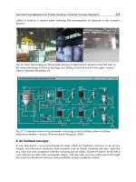
Fig. 6. Schematic diagram of laboratory apparatus for testing catalyst
The apparatus consisted of model gas feeding system and dosage system, catalytic reactor
and analyzer for determining the content of nitric oxide in the gas. The reactor was supplied
with the mixture of nitrogen and air enriched with water steam. The mixture contained,
depending on the type of test, a specific amount of nitric oxide. The concentration of NO
was measured at the entrance and exit of the reactor.
10 cm
3
of the tested catalyst (grain fraction 0,6 – 1 mm) was put in the electrically heated
reactor (Fig. 6). The mixture of gases from the mixer was directed into the SCR reactor. The
reactor was equipped with an electrical heating jacket powered by auto transformers. The
temperature of the reactor at the entrance and at the exit of the catalyst bed was measured
by means of thermocouples connected with the temperature regulator. Additionally, the
reactor was equipped with an isolation mantle in order to provide isothermal conditions
inside it. Gases coming out of the reactor went into an analyzer through the filters. Nitric
oxide contents at the entrance and at the exit of the catalyst bed was determined with using
of MSI 2500 analyzer.
Selective Catalytic Reduction NO by Ammonia
Over Ceramic and Active Carbon Based Catalysts
367
Activity of catalyst – reaction of denitriding the combustion gases – is determined according
to the following formula:
= 100( c
o
– c
k
)/c
o
[%]
c
o
concentration of NO
x
before reactor
c
k
concentration of NO
x
after reactor
The conditions of the process were: temperature range from 150
o
C to 500
o
C, volume speed
of the gas flow was GHSV=3000 m
3
/m
3
•h
-1
, oxygen content in the model gas = 6 %, NO
content within the range ~ 500 ppm, ratio NH
3
/NO equal to 1, water vapor content in the
model gas ~ 1 %, Model gas and gas leaving the reactor was analyzed using the MSI 2500
analyzer.
The results of investigation of catalyst activity of 8,78 wt% CuO; 3,63 wt% MnO; and 8,78
wt% CuO with 3,63 wt% MnO catalysts are presented in Fig.7.
Fig. 7. Catalyst activity
As we see ( Fig. 7- left) in range of temperatures above 400
o
C take places ammonia combustion
reactions and take place decreasing of NO conversion.
4.4 Catalyst deactivation
The aging of the catalyst is caused by several mechanisms acting simultaneously, which can
be divided into three groups:
- thermal deactivation,
- mechanical deactivation,
- chemical deactivation.
Thermal deactivation is caused by raising the catalyst temperature to about 600-650°C,
which causes irreversible degradation of the carrier. Presumably this is connected with a
change of the porous structure of the catalyst as well as blocking of some of the pores by
molten components of the active phase. There is no doubt that the porous structure of the
catalyst changes, and its specific surface area diminishes while the average pore radius
increases. There are also crystallographic changes: amorphous silica crystallises to form a-
cristobalite.
Mechanical deactivation is caused by blockade of the gaps between catalyst granulates
(or channels in the monolith) by particulates carried by gas. This type of deactivation
depends mainly on the purity of the gas fed to the reactor. Chemical deactivation or catalyst
poisoning are usually regarded as rapid loss of activity caused by reaction of trace
impurities with the catalyst. However, there are many substances that react with its
Heat Analysis and Thermodynamic Effects
368
components resulting in a reduction of the activity or deterioration of its mechanical
strength. Most known catalyst poisons, such as arsenic oxides, nitrogen oxides, carbon
monoxide, lead, and mercury are harmless in small quantities. Hydrogen chloride and
chloride acting for a longer time can cause a loss of catalyst activity [23].
4.5 Methods of installing catalysts
The level of the required catalyst temperatures determines where catalysts are incorporated.
Generally speaking, catalytic systems can be installed on boiler exhaust gas lines
irrespective of other installations, e.g. desulphurisation of exhaust gases (DESOX). However,
in practically all exhaust gas purification solutions, the DENOX and DESOX systems are
designed in a comprehensive manner. This creates various possibilities for locating SCR
installation in the exhaust gas line downstream the boiler.
Fig. 7-12 shows installation options for the SCR systems. Fig. 7 shows the most common
version of SCR installation, the so-called high dust (with high ash content in exhaust gases).
Fig. 7. “High dust” system with desulphurisation and denitrification.
Fig. 8 presents a “Low dust” only for organisation purposes. It is used exclusively in the
USA, in boilers with hot electrostatic precipitator.
The systems presented in Fig. 9 and 10 also constitute “low dust” solutions but due to their
incorporation at the end of the exhaust gas line they are commonly referred to as “Tail End”.
Fig. 9 shows a very interesting “High dust” concept with the so-called DENOX - LUVO, in
which heating elements in special execution have catalytic properties.
The use of RAH (LUVO) as a two-function device by extending its heat-exchanging function
to include a catalyst function, would result in a considerable reduction in the cost of
implementing the SCR method.
The proposed [43-45] way of using the regenerative air heater (RAH-SCR) as a catalyst
would eliminate the necessity of building a SCR reactor, as the existing RAH could then be
used. The trials will enable to compare the activity levels of industrial-scale manufactured
catalysts in reduction of NO
x
using ammonia. A series of trials is also anticipated, during
which fly-ash from boilers will be added to flue gas. It will enable researchers to assess
durability and time-based changes of reduction efficiency of the catalysts at variable ash
loads (fly-ash which may ‘pollute’ the catalyst).
Figures 12 show detailed diagrams of the most interesting SCR systems. Ammonia injection
is placed at least 3 m upstream of the catalyst.
Fig. 13 shows balance of ammonia at the individual devices of the HD system. It is very
important that sulphur oxides are removed from exhaust gases prior to the process of
Selective Catalytic Reduction NO by Ammonia
Over Ceramic and Active Carbon Based Catalysts
369
selective catalytic reduction, because it prevents the formation of ammonium sulphates that
can form in the following reactions:
Fig. 8. “High dust” system with DENOX LUVO.
Fig. 9. Classic “Low dust” system of SCR with desulphurisation.
System downstream of desulphurisation System upstream of desulphurisation
Fig. 10. “Tail end” system
2 SO
2
+ O
2
2 SO
3
2 NH
3
+ SO
3
+ H
2
O (NH
4
)
2
SO
4
NH
3
+ SO
3
+ H
2
O NH
4
HSO
4
Heat Analysis and Thermodynamic Effects
370
Fig. 11. “Tail end” system downstream of desulphurisation with DENOX GAVO.
Fig. 12. DENOX installation
Fig. 13. NH
3
balance at SCR – “HD”
The forming ammonium sulphate causes clogging of catalyst beds and corrosion of the SCR
installation. This is an especially serious problem at power stations fuelled by bastard coal.
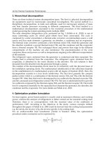
The effects of particulate matter, which may cover the catalyst surface, is very clearly visible
on the following photographs (Fig. 14)
Initially, catalytically-active components of catalysts were pure noble metals, such as:
platinum, rhodium, and palladium. The benefits of application of those metals were:
- high activity,
- resistance to deactivation.
However, the high price of noble metals lead to the development of cheaper and equally
effective catalysts, such as:
Selective Catalytic Reduction NO by Ammonia
Over Ceramic and Active Carbon Based Catalysts
371
- catalysts based on transition metal oxides (V
2
O
5
, NiO) deposited on carriers (TiO
2
,
Al
2
O
3
, SiO
2
, ZrO
2
),
- zeolites containing Cu,
- metals such as Fe, Mn, or Cu deposited on carbon and mineral-carbon carriers.
Fig. 14. View of a catalyst SCR.
Currently, more and more attention is devoted to carbon materials and their use in catalytic
processes. Especially strong interest is generated by active carbon as a carrier of the active
phase of catalysts. It has several important benefits thanks to which it has been widely used
is different fields of chemistry. Active carbon is characterised by a very well-developed
surface (from 1000 to 1500 m
2
/g), diverse pore diameters, and high adsorption capacity.
For these reasons, it is used as a component of water purification filters or as the main
component of canisters in gas masks, capturing such hazardous substances as: some organic
compounds, sulphur oxides, hydrogen chloride, ammonia, hydrogen cyanide, or nitrogen
oxides. Active carbon is also used in medicine, administered by the oral route in some
cases of poisoning. As a carrier of the active phase of catalysts, it is used e.g. in organic
chemistry. In industrial processes, such as SCR, active carbon can be connected with
mineral compounds, which significantly increases its mechanical strength as an active phase
carrier.
The catalytic method with the use of ammonia was developed by Englehard Corporation in
the United Stated in 1957. The first SCR installations used platinum catalyst for nitrogen
oxide reduction. However, its use was abandoned due the fact that the reduction reactions
took place at temperatures similar to the flashpoint of the ammonia and air mixture.
Currently, most catalysts in use are made of a carrier – titanium oxide (TiO
2
) and the active
phase – tungsten oxide (WO
3
) and/or vanadium oxide (V
2
O
5
).
In the process of selective catalytic reduction of nitrogen oxides, in addition to the active
phase the temperature of the process is also important. It is recommended to use
temperatures in the range from 300
o
C to 400
o
C, so optimum conversion of nitrogen oxides
can be obtained. At temperatures above 450
o
C ammonia is burnt to NO.
4NH
3
+ 5O
2
4NO + 6H
2
O
On the other hand, too low process temperature (under 200
o
C) may lead to the formation of
ammonium nitrites and nitrates. When exhaust gases contain a lot of particulates (approx.
20 g particulate per 1 m
3
) a reactor is used, in which the fuel jet is directed vertically
downwards to the catalyst bed. Typically, three or four catalyst layers are used, placed over
each other (Fig.16). Each layer consists of certain number of buckets containing catalysts,
which facilitates ongoing replacement of spent catalysts starting from the top of the reactor.
This way each bed is periodically subjected to the process of cleaning of deposits by means
of overheated water vapour.
Heat Analysis and Thermodynamic Effects
372
The technique of manufacture of catalytic monoliths was first perfected in Japan. For dusty
exhaust gases two types of flow profiles were developed: plate and honeycomb.
Fig. 16. Diagram of the SCR reactor (right - the element and package of ceramic catalysts)
Fig. 17. Types of industrial catalysts in use.
In Japanese metal catalysts the primary material is titanium oxide TiO
2
mixed with glass
fibre, covered on the outside with tungsten and vanadium pentoxide.
Besides high investment cots, catalysts containing those heavy metals also create serious
problems connected with their storage after they are spent. Catalysts have a lifetime of 2 to 7
years. In their search for cheaper solutions, German companies developed their own iron-
chrome (Didier) and ceramic (Mannesman) catalysts. Spent ceramic catalysts are powdered
and used as a raw material for the production of new catalysts.
Plate catalysts are made in the form of blocks similar to the so-called baskets of heating
elements of rotating air heaters. Plate catalyst blocks are assembled as packages (modules),
as shown in Fig. 17.
Honeycomb catalysts are made in the form of small-scale elements, which are then
assembled into modules.
Catalysts are installed in the exhaust duct in 3 or 4 layers, with a gap between them to
incorporate cleaning devices (blowers).
Table 5 shows SCR device suppliers to illustrate the dynamics of development of the
catalyst manufacturing industry in Germany supplying the power industry. Table 6 shows
types of catalysts used in the Japanese power industry. In table 5 of note are unmentioned
catalysts based on carbon chemistry (active carbon, active coke). This technology will be
presented later in the text.
Catalytic methods, included among non-waste methods, due to lack of waste are an
alternative to the waste methods. They are characterised by a high degree of exhaust gas
purification (simultaneous removal of NO
x
and SO
2
) and achievement of a commercial
product in the form of concentrated sulphuric acid, sulphur, or other products. They involve
catalytic oxidation of SO
2
to SO
3
and three-stage condensation of exhaust gases: at the first
Selective Catalytic Reduction NO by Ammonia
Over Ceramic and Active Carbon Based Catalysts
373
stage - with condensation of concentrated sulphuric acid, at the second stage – after
moistening of sulphuric acid of a lower concentration, at the third stage – after moistening
of hydrogen chloride and hydrogen fluoride.
Supplier Licence Type of catalyst
Deutsche Babcooc Kawasaki (Jap.) Honeycomb-type based on titanium oxide (TiO
2
)
Deutsche Rauchgas
Babcoc- Hitachi
(Jap.)
Plate-type based on titanium oxide
Dider own (Germany) Iron-chrome
EVT Mitsubishi (Jap.) Honeycomb-type based on titanium oxide (TiO
2
)
Flakt Hitachi - Zosen (Jap.) Plate-type based on titanium oxide
GEA Engelhard Honeycomb-type based on titanium oxide (TiO
2
)
Linde Norton (USA) Powder catalyst
Knauf Research
Cottrel
USA
Plate-type or honeycomb-type based on titanium oxide
(TiO
2
)
Steinmuller Ishikawajima Honeycomb-type based on titanium oxide (TiO
2
)
Mannesmann own Molecular sieve, ceramic
Holter- Lurgi Hitachi - Zosen (Jap.) Plate-type based on titanium oxide
Thyssen MHI Honeycomb-type based on titanium oxide (TiO
2
)
Uhde Bergbau-Forschung Active coke
Uhde- Lentjes
Babcoc - Hitachi
(Jap.)
Plate-type based on titanium oxide
Table 5. Companies offering SCR devices
Name of the
power station
Power unit
capacity Mw
Type of
catalyst
Concentration of
NO,[mg/Nm
3
]
SCR
effectiveness,
%
input output
Takehara
2x250; 700;
2x250;
plate 700-500 134-96 81
Shimono Seki 175 honeycomb 840 360 57
Shin Ube 156 honeycomb 800 280 65
Mizushima 156 plate 700 240 65
Saijo 156; 250; honeycomb 760-660 260-180 65-70
Table 6. SCR systems in larger carbon units in Japan
It should be emphasized that those are the methods of the future and they already have
their applications in the world, e.g. Münster in Germany and Vendsyssel power station in
Denmark. However, they are characterised by an extensive centre of catalytic oxidation and
reduction of gas contaminants as well as centres of condensation of separated contaminants
with complex devices. They do not require the use of sorbents and they provide end-
products with specific commercial properties.