Human Musculoskeletal Biomechanics Part 4 pptx
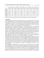
Bạn đang xem bản rút gọn của tài liệu. Xem và tải ngay bản đầy đủ của tài liệu tại đây (3.34 MB, 20 trang )
Motion Preservation and Shock Absorbing in Cervical and Lumbar Spine:
A New Device for Anterior Cervical Arthroplasty, for Anterior or Posterior Lumbar Arthroplasty
51
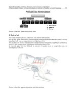
Picture 2. Cervical spine study group, 2004
2. State of art
The surgical approach used, until now, was anterior arthroplasty.
For cervical spine, the anterior extrapharingal-presternocleidomastoideo approach is a very
tested and safe way, in reoperation as well (pictures 3, 4).
The incidence of cervical intraoperative complications (Haematoma, dysphagia, dysphonia),
are 6.2%
; late complications (ossification, dislocation) about 5.2%.
In cervical spine it is not difficult to convert, if needed, even in long follow-ups, an
arthrtoplasty to fusion.
Picture 3. Cervical approach, position and skin incisions
Human Musculoskeletal Biomechanics
52
Picture 4. Cervical approach, surgical way
For lumbar spine, the anterior trans-peritoneal and retroperitoneal approach (most used )
are less safe (more in reoperations), because of gross vesselles and and nervous plexis,
attached to the spine: even slight dislocation, sometime, may causes neurological damages
or important vascular bleeding.
This needs a long learning curve, doing the operations with the collaboration of general or
vascular surgeons.
The conversion arthroplasty-fusion may be very hard in lumbar spine.
The heterotopic ossification, with consequent block of the prosthesis and intervertebral
fusion, increases from 12% to 17.8%:
perioperative non steroid anti-inflammatory therapy
(FANS) and intraoperative “wash-out”, works out to be the best prevention.
The titanium alloys and the ceramics guarantee a better MRI compatibility than cobalt-
chromium alloys or steel.
The biocompatibility is very important for post-operative controls, better if MR fast spin
echo imaging (than T2 imaging)
These indications in disc herniation, after surgical disc removal, in alternative to anterior
intervertebral fusion, preferring one single level, no more than two levels, from C4 to C6,
from L4 to S1, not responding to conservative treatments, if there is a good pre-operative
range of motion (ROM) to ward after the operation, for a long time and articular joints
preservation (testing by MRI, bone CT scan and dynamic RX film), to avoid adjacent-
segment degeneration in a long post-operative follow-up, without pre-operative bone
fractures, bone tumours, bone deformities or bone infections.
Degenerative discopathy, about ten years ago, in USA, was estimated $50 billion of annual
health costs.
Arthroplasty, as alternative to fusion, was said before (pictures 5, 6).
Motion Preservation and Shock Absorbing in Cervical and Lumbar Spine:
A New Device for Anterior Cervical Arthroplasty, for Anterior or Posterior Lumbar Arthroplasty
53
Picture 5. Cervical fusion
Picture 6. Cervical arthroplasty
Fusion after discectomy is a consolidate surgical treatment for disc herniation.
A lot of papers, in literature, confirm long term follow-up, its effectiveness and safeness.
In last few years, some authors have reported it the other way.
Motion preservation and adjacent –segment degeneation’s prevention are the Key words of
arthroplasty.
The first argument is intuitive: arthroplasty, through non fusion, preserves the motion in the
operated segment .
For the second question, biomechanics and kinematics, teach that in a series of mobile
segments, when one of them is blocked or unable to shock absorb or cushioning functions,
the caudal and the cranial segments suffer a mechanical stress, expressing in a motion
alteration.
Human Musculoskeletal Biomechanics
54
These alteration may cause structural and anatomical alterations, as well to produce clinical
failures.
From a review of literature, these are the most important elements “pro” arthroplasty vs
fusion:
1. motion maintenance at treated segment (stability of range of motion data: 7.4° one year
post-operation and 7.9° five years post operation)
2. reduction of adjacent-discal-segment degeneration
3. reduction of intradiscal-pressure in cranial and caudal intervertebral disc
4. no aggravations of pathologies in cranial and caudal disc, if presents before the
operation
5. more patient’s satisfaction, for both non post-operative orthosis dressing and early
return to work.
Recently, only one paper about the not unequivocal significant utility of arthroplasty vs
fusion has been reported.
In my personal surgical experience, consists of 60 patients treated with cervical
microsurgical discectomy (MD group) vs 60 patients treated with cervical microsurgical
discectomy and fusion (using titanium or peek devices) (MDF group) vs 60 patients treated
with microsurgical discectomy and arthoplasty (MDA group), using “Discover” device
®
(picture 7).
Picture 7. “Discover” device
®
.
The clinical and radiological follow-up was for a maximum period of 48 months.
The preliminary extrapolated data seems to confirm what had been reported before, from 1
to 5 points, encouraging and authorizing cervical arthroplasty vs cervical fusion, in discal
pathology: rigorous and careful indication for patient selection, more long, shareable and
verifiable follow-ups are imperative.
11.6%of clinical failures in MD group.
3. The new device
(patented, all rights reserved)
One of the most important limitations of discal prosthesis (cervical and lumbar) is the axial
compression.
Motion Preservation and Shock Absorbing in Cervical and Lumbar Spine:
A New Device for Anterior Cervical Arthroplasty, for Anterior or Posterior Lumbar Arthroplasty
55
In a non pathological lumbar disc, for example, it ranges from 0.5 to 1.5 mm: this is a very
important element for shock absorbing and cushioning.
Standing to the literature data, until now, no disc prosthesis has these characteristic.
Another significant limitation, only for lumbar prosthesis is, until now, the impossibility to
place it by a posterior surgical approach, more handy, and safer than anterior approach.
These new devices (picture 8) try to satisfy the two conditions just described.
For the second question, was designed a particular way, standard sized, not more bulky
(thanks to particular material used) so to introduce the device, after a bilateral posterior
discectomy, after a bilateral laminar reduction, by a monolateral way into the intervertebral
emptied and gently distracted space.
Picture 8. The new device
The device is introduced perpendicular to the intervertebral space, by a dedicated
instrument and, at the anterior third of the space (verified by intraoperative RX film), by the
same instruments, rotated in 180° according to the intervertebre space’s axis (picture 9).
Picture 9. The device and its instruments . During the introduction (on right), after the 180°
rotation (on left)
Human Musculoskeletal Biomechanics
56
Then, unhooked the dedicated instruments, the devices remain anchored in situ after a
gentle intervertebral space compression, even through its superior and the inferior tops,
rough and teeth fitted, that favour a fusion, with the corresponding vertebral end plates
(picture 10).
Picture 10. The device and its instruments during the introduction and rotation (on left) the
device after its definitive collocation (on right)
To the second purpose, particular attention was given to the structural design, to the
materials and to the sequence of the components in their assembly, in order to give to the
device features similar to the non pathological intervertebral disc: bone and
biocompatibility, MRI compatibility, strength to static load for maximum 330 kg , 4°-5° of
maximum inclination on all side and, mostly (picture 11), features not held by other devices
until now, shock absorbing, load sharing and chushioning .
Picture 11. The device’s inclination in a front view.
The use of two rough teeth fitted titanium tops (superior and inferior) , opposite to the
corresponding vertebral and plates (“A” in picture 12), guarantee bone and
biocompatibility, MRI compatibility, strength to static loads for maximum 330 kg.
Their mutual articulation, by a titanium spherical node (fitted of a security self-stoppage
system), behaving like a “spring –cup” (“B” in picture 12), create a metal/metal antifriction
interface securing strength, motion preservation and shock absorbing.
Motion Preservation and Shock Absorbing in Cervical and Lumbar Spine:
A New Device for Anterior Cervical Arthroplasty, for Anterior or Posterior Lumbar Arthroplasty
57
Finally, the use of an organic polymer thermoplastic (Polyether-Ether-Ketone, “PEEK”) to
shape a “bed” in which is collocated the titanium spherical node (“C” in picture 12)
complete the shock absorbing function, giving load sharing and cushioning features, elastic
response to the loads.
Picture 12. Structural devices view, frontal (left) and lateral (right)
4. Conclusions
The literature data, until now, had cautiously encouraged the non fusion versus the fusion,
in the surgical treatment of degenerative discal pathology (in cervical and lumbar spine).
However, the elements that prefer arthroplasty over fusion were, in my opinion, mainly
three:
1. a more long follow-up for fusion cases
2. the impossibility of a posterior surgical approach in lumbar spine
3. the impossibility to have a really shock absorbing, load sharing and chushioning
function, but only motion preservation and strength to static load (both in cervical and
in lumbar spine).
These studies, that led to the design and the creation of these device, aim to fill the gaps just
emphasized above, giving a new prosthesis both in cervical spine (in order to really shock
absorb, load share and cushioning functions) and in lumbar spine (in order both in these
same features and in the really possibility to perform a posterior surgical approach, certainly
more safe for the patients and experienced for the spine surgeons.
Only a long follow-up may validate or not these work.
5. Acknowledgment
Andrea Bedeschi, engineer in Ferrara (Italy)
6. References
Bartles, R.H.M.A et al., 2010. No justification for cervical disk prostheses in clinical practice:a
meta-analysis of randomized controlled trials. Neurosurgery, Vol.66, No.6, (June
2010), pp.1-8
Human Musculoskeletal Biomechanics
58
Brunner, H.J. et al., 2010. Biomechanics of polyaryletherketone rod composites and titanium
rods for posterior lumbosacral instrumentation.J Neurosurg Spine, Vol.13,
(December 2010), pp.766-772
Coric , D.et al., 2010.Prospective study of cervical arthroplasty in 98 patients involved in 1 of
3 separate investigational site with a minimum 2-year follow-up.J Neurosurg Spine,
Vol 13, (December 2010), pp. 715-721
Fehlings, M.G. et al., 2010.Motion preservation following anterior cervical discectomy.J
Neurosurg Spine, Vol 13, (December 2010), pp.297-298
Logroscino, C.A.et al., 2007. Artroplastica vertebrale: stato dell’arte della chirurgia protesica
cervicale e lombare G.I.O.T., Vol 33 (suppl.1), pp.155-161
Maida, G.et al., 2008. Artroplastica cervicale: la nostra esperienza.Rivista Medica, Vol 14,
No.3, (September 2008), pp.53-56, ISSN 1127-6339, ISBN 978-88-8041-012-6
Maida, G.et al., 2009.60 patients follow-up, from 6 months to 2 years, in patients treated with
discover arthroplasty after discectomy and preliminary comparison with
discectomy and fusion and discectomy alone. Eur.Spine.J, Vol 18, (May 2009),
pp757
Ryu, K.S. et al., 2010.Radiological changes of operated and adjacent segments following
cervical arthroplasty after a minimum 24-month follow-up: comparison between
the bryan and Prodisc-C-devices. J Neurosurg Spine, Vol 13, (September 2010),
pp.299-307
Part 2
Musculoskeletal Biomechanics
4
Biomechanical Characteristics of the Bone
Antonia Dalla Pria Bankoff
University Of Campinas
Brazil
1. Introduction
The bone tissue is strong and one of the most rigid structures of the body due to its
combination of inorganic and organic elements. The minerals calcium and phosphate,
together with collagen, constitute the organic element of the bone being responsible for
approximately 60 to 70% of the bone tissue. Water constitutes approximately 25 to 30% of
the bone tissue weight. (Alberts et al., 1994; Junqueira & Carneiro, 1997, 1999).
The bone tissue is a viscous-elastic material whose mechanical properties are affected by its
deformation grade. The flexibility properties of the bone are provided by the collagen
material of the bone. The collagen content gives the bone the ability to support tense loads.
The bone is also a fragile material and its force depends on the load mechanism. The
fragility grade of the bone depends on the mineral constituents that give it the ability to
support compressive loads. (Alberts. et al., 1994; Junqueira & Carneiro, 1997, 1999).
Re-absorption and Bone Deposit - Bone is a highly adaptive material and very sensitive to
disuse, immobilization or vigorous activity and high load levels. The bone tissue can be
separated and may change its properties and setting in response to the mechanical demand.
It was determined at first by the German anatomist, Julius Wolff, that gave us the theory on
the bone development named Wolff Law, that says: "Each change in the form and function
of a bone or only its function is followed by certain definitive changes in its internal
architecture, and secondary changes equally definitive in its external compliance, in
accordance to the mathematics law". (Alberts et al., 1994; Junqueira & Carneiro, 1997, 1999).
2. Bone strength and hardness
The behavior of any material under different load conditions is determined by its strength
and hardness. When an external force is applied in a bone or in any other material, there is
an internal reaction. The strength may be assessed by checking the relation between the load
imposed (external force) and the quantity of deformation (internal reaction) that takes place
in the material, known as load-deformation curve. (Holtrop, 1975).
Anisotropic Characteristics Bone tissue -Is an anisotropic material, indicating that the bone
behavior will change depending on the direction of the load application. In general, the
bone tissue may lead to higher loads in the longitudinal direction and a lesser quantity of
load when applied over the bone surface. The bone is strong to support loads in the
longitudinal direction because it is used to receive loads in this direction. (Holtrop, 1975).
Viscoelastic Characteristics - The bone is also viscoelastic, which means that it responds
differently depending on the speed to which the load is applied and the length of the load.
Human Musculoskeletal Biomechanics
62
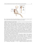
Fig. 1.1. This mean section of the proximal tip of the femur shows both the compact bone
and the sponge bone. The dense compact bone covers the external part of the bone, going
downside in order to form the bone body. The sponge bone is found in the tips and is
identified by its truss appearance. Watch for the curvature in the trabeculae, which is
formed to support the stresses. Bankoff (2007, p. 122).
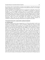
Fig. 1.2. The bone is considered anisotropic because it responds differently when the forces
are applied in different directions. (A) The bone can lead to great forces applied in the
longitudinal direction. (B) The bone is strong when it leads with forces applied transversally
crossing its surface. Bankoff (2007, p. 123).
Trabeculae spongy bone
Compact bone
A
B
A
B
Spongy bone
Biomechanical Characteristics of the Bone
63
In very fast speeds of load placement, the bone can lead to higher loads before it fails or
breaks. As showed in FIGURE 1.3, the bone that receives the load slowly breaks with a load
that is approximately half of that it could support if the load was more quickly applied.
Elastic Response - When the load is firstly applied, a bone is deformed by a change in the
extent or angular format. The bone is deformed up to 3%. This is considered the elastic
amplitude of the load-deformation curve because, when the load is removed, the bone is
recovered and goes back to the original format or extent. The stress-distension or load-
deformation curve is presented in FIGURE 1.4. An exam of this curve may be used in order
to determine if a material is hard, flexible, fragile, strong or weak. The curve showed could
represent a material that is strong and flexible. (Hay, 1982; Holtrop, 1975).
Plastic Response - With the continuous placement of load on the bone tissue, its
deformation point is reached, after which the external fibers of the bone tissue will start to
cede, experiencing micro-breaks and disconnection of the material within the bone. (Hay,
1982; Holtrop, 1975).
Fig. 1.3. The bone is considered viscoelastic because it responds differently when it receives
loads in different speeds. (A) When it receives the load quickly, the bone responds more
rigidly, and may handle a higher load before it breaks. (B) When it receives the load slowly,
the bone is not so rigid or strong, breaking under lesser loads. Bankoff (2007, p.123 ).
To which we name plastic or non-elastic phase in the load-deformation curve. The bone
tissue starts to deform permanently and eventually breaks if the load continues in the non-
elastic phase. Thus, when the load is removed, the bone tissue does not retake the original
extent and is permanently elongated. (Hay, 1982; Holtrop, 1975; Bankoff, 2007).
Strength - The strength of the bone or any other material is defined by the point of failure or
by the load sustained before the failure. The strength may also be analyzed in terms of
storage of energy, the area under the load-deformation or stress-distension curve. (Hay,
1982; Holtrop, 1975; Bankoff, 2007).
Load
A
B
Deformatio
n
Fracture
Fracture
Human Musculoskeletal Biomechanics
64
Hardness - The hardness, or elasticity module of a material, is determined by the decrease of
the load-deformation curve (FIGURE 1.4) during the amplitude of the elastic response and is
represented by the resistance of the material to the load as the structure is deformed. This
response occurs in many materials, including bones, tendons and ligaments. The stress-
distension curve for flexible, fragile materials and for the bone is represented in FIGURE 1.5.
(Choi & Goldstein, 1992).
Fig. 1.4. The stress-distension curve and the load-deformation curve illustrate the
performance strength characteristic of a material when subjected to the load. When the load
is applied, there is an (A) initial elastic response that eventually reaches a (B) deformation
point, getting into the (C) plastic response when the material is deformed permanently or is
broken. The strength of the material is determined by the (D) energy or area under the
curve. The hardness of a material, called elasticity module is determined by the (E)
inclination of the curve during the elastic response phase. Bankoff (2007, p. 123).
A hard material will respond with a minimum deformation to the load increase. When the
material fails in the end of the elastic phase, it is considered a fragile material. The glass is an
example of fragile material. The bone is not so hard as the glass or metal, and, differently of
those materials, it does not respond linearly, because it cedes and deforms not uniformly
during the load placement phase. The higher the load imposed to the bone, the higher the
deformation. In addition, if the load exceeds the elastic limits of the material, there will be a
permanent deformation and failure of the material. If a material continues to over-elongate
and over-deform in the plastic phase, it is known as flexible material. (Choi & Goldstein, 1992).
The skin is an example of material that is deformed considerably before the failure. The
bone is a material that has properties that respond in both the fragile and the flexible mode.
(Choi & Goldstein, 1992).
A- Elastic re
g
io
n
D- Elastic energy
Stress (Load)
B- Deformatio
n
Fracture/ Failure C- Plastic re
g
io
n
E- Modulus elasticit
y
Stress
Distensio
n
Distension (deformation)
Stress
Distensio
n
Biomechanical Characteristics of the Bone
65
Fig. 1.5. Such stress-distension curves illustrate the differences of behavior among (A)
flexible material, (B) fragile material and (C) bone, that has both fragile and flexible
properties. When the load is applied, a fragile material responds linearly and fails or breaks
before experiences any permanent deformation. The flexible material will get into the plastic
area and will be considerably deformed before the failure or break. The bone is slightly
deformed before the failure. Bankoff (2007, p. 124).
A plurality of materials was signaled in a graph of FIGURE 1.6 in accordance to its strength
and hardness. Examples of materials considered hard and weak are glass and copper, hard
and strong materials are steel, iron and gold. Flexible and strong materials are fiberglass and
silk, and flexible and weak materials are oak-wood, lead and a spider web. The bone is
considered a flexible and weak material. (Choi & Goldstein, 1992; Cook et al., 1987).
Stress and Distension — Another way to assess the behavior of the bone or any other
material when subjected to the load is to measure the stress, or the load by area of
transversal section and the distension, or deformation, regarding the original extent of the
material. A stress-distension curve may be produced on such a way that, as the load-
deformation curve, illustrates the mechanical behavior of the material and may be used in
order to check the strength and hardness of the material (FIGURE 1.4). (Choi & Goldstein,
1992; Cook et al., 1987).
The load-deformation curve of a material in particular seems exactly to the stress-distension
curve for the same material and is interpreted on the same way described previously using
the load-deformation curve. The only difference among the curves is in the units used to
represent each one of them. The load-deformation curve is represented by absolute values of
load and deformation, while the stress-distension by relative values regarding the material
extent and transversal section. The benefit of producing a stress-distension curve is that the
standardization regarding the unit of the area and extent allows for the comparison of
different materials. (Cook et al., 1987; Choi & Goldstein, 1992).
Stress or Normal Distension and Shear — The stress and distension may occur
perpendicularly to the transversal section plan of the object that receives the load, known as
normal stress and distension, or parallel to the transversal section plan, known as shear
stress and distension. For example, a normal distension involves a change in the extent of an
object, while distension with shear is characterized by a change in the original angle of the
object. (Cook. et al., 1987; Schaffler & Burr, 1988; Choi & Goldstein, 1992).
A - Flexible material
B - Fragile material
C-Bone
Stress
Distension
Human Musculoskeletal Biomechanics
66
Fig. 1.6. The strength and stiffness of a variety of different materials are represented by four
quadrants representing flexible and weak materials which is (A); flexible and weak; (B) hard
and weak (C) hard and strong; and (D) flexible and strong. Watch that the bone is classified
as flexible and weak together with other materials such as spider web and oak wood.
(Adapted from Hamil and Knutzen, 1999 p.44) Bankoff (2007, p. 124).
3. Load types
The skeletal system is subjected to a variety of different types of forces on such a way that
the bone receives loads in different directions. There are loads produced by the weight
sustentation, by the gravity, by muscle forces and by external forces. The loads are applied
in different directions producing forces that may vary from five different types:
compression, tension, shear, curvature or torsion (Shipman, Walker & Bichell, 1985).
The skeletal system injury can be produced by applying a high-magnitude single strength of
one these types of load or by repeated application of low-magnitude loads over a long
period. The second type of injury in the bone is called stress fracture; fatigue fracture or
bone distension. FIGURE 1.8 shows the X-ray photo of a stress fracture on the metatarsus.
These fractures occur because of cumulative microtrauma imposed on the skeletal system,
when the placement of loads on the system is so frequent that the process of bone repair
cannot be equal to the breakdown of the bone tissue. (Shipman, Walker & Bichell, 1985;
Egan, 1987).
Strength
Hardness
Fiber
g
lass
Flexible stron
g
Hard Stron
g
Steel
Iro
n
Gold
Copper
Glass
Bone
Oak-wood
Lead
Sil
k
Spider web
Flexible wea
k
Hard weak
Biomechanical Characteristics of the Bone
67
Fig. 1.7. The stress, that is the force by area unit, may occur perpendicularly to the plan
(normal stress) as represented in (A), or in parallel to the plan (stress with shear)
represented in (B). The distension, that is the deformation of the material, is represented in
(C) normal distension, in which the extent varies and (D) distension with shear, in which the
angle is changed. Bankoff (2007, p. 125).
Stress=stren
g
th/ area
Tensile stren
g
th
Stren
g
th
A - Normal stress
B - Stress with
shear
Stren
g
th
Com
p
ressive stren
g
th
Com
p
ressive stren
g
th
C - Normal distension
D - Distension with shear
Distensio
n
= Chan
g
in
g
the len
g
th or an
g
le
Human Musculoskeletal Biomechanics
68
Compressive Strengths — A compressive strength presses the edges of the same bone at the
same time; and is produced by muscles, weight support, gravity or some external load that
come down the length of the bone. Compressive stress and distension within the bone
causes bone shortening and extension and bone absorbs maximum stress in a plane
perpendicular to the compressive strength (Figure 1.9 -A and B). Compressive strengths are
necessary for the development and growth of the bone. The stresses and distensions
produced by the compressive strengths and other strengths are responsible for facilitating
the deposition of the bone material. (Egan, 1987).
If a large compressive strength is applied and if the loads exceed the structure stress limits,
fracture occurs. There are numerous places in the body prone to fracture or compressive
injuries. A compressive strength is responsible for patellar pain by softening and destruction
of cartilage under the patella, known as chondromalacia patellar chondromalacia. As knee
articulation moves in amplitude of movement, the patella moves up and down in its sulcus.
The load between the patella and femur increases and decreases until a point where the
patellofemoral compressive strength is greater than about 50 degrees of flexion and lower in
full extension or hyperextension of knee articulation. High compressive strength in flexion,
primarily on the lateral patellofemoral surface, is the source of the destructive process that
breaks down cartilage and underlying surface of the patella. (Egan, 1987; Schaffler & Burr,
1988; Hoffman & Grigg, 1989).
Fig. 1.8. Stress fractures occur in response to the excessive loads on the skeletal system so
that cumulative microtrauma occurring in the bone. A stress fracture in the second
metatarsal, as shown above, is caused by running on hard surfaces or using hard shoes. It is
also associated with people with high arches and can be created by fatigue of neighbors
muscles. Bankoff (2007, p. 126).
Biomechanical Characteristics of the Bone
69
Compression is also a source of fractures in the vertebrae. Fractures have been reported in
the cervical area in activities like water sports, gymnastics, wrestling, rugby, ice hockey and
American football. Normally, the cervical spine is slightly extended with a convex curvature
previously, if the head is lowered, the cervical spine is rectified to approximately 30 degrees
of flexion. If strength is applied against the top of the head when you are in this position, the
cervical vertebrae get a load to down in its extension caused by a compressive strength,
creating a dislocation or fracture-dislocation of the vertebral facets. When spearing or
butting (throw of the player by other of the team) with the head in flexion was banned in
American football, the number of cervical spine injuries has been drastically reduced. (Cook
et al., 1987; Fine et al., 1991; Halpbern & Smith, 1991).
There are also reports of compression fractures in lumbar vertebrae of weightlifters,
defenders of American football or gymnasts who had overwhelmed the vertebrae in the
spine being with hyperlordotic or lordotic position. Finally, compression fractures are
common in subjects with osteoporosis. (Matheson et al., 1987; Fine et al., 1991; Halpbern &
Smith, 1991).
Fig. 1.9. A The skeletal system is subject to a variety of loads that alternate within the bone.
The solid layout in the femur above indicates the original state of the bone tissue. The
colored area shows the effect of the applied strength on the bone. (A) A compressive
strength causes shortening and extension, (B) a tensile strength causes narrowing and
elongation (C) shear strength and (D) torsional strength creates an angular distortion, and
(E) the bending strength includes all changes seen in compression, tension and shear.
Bankoff (2007, p. 126).
a - Com
p
ressio
n
b-Tensio
n
c-Shear
d-Torsio
n
e-Bendin
g
Human Musculoskeletal Biomechanics
70
Spondylolysis may occur and a stress fracture of the vertebrae interarticular part. Specific
weight lifting that have high incidence of this fracture are the clean and jerk (direct weight
lifting from the ground up above the head). It also occurs in gymnasts and is associated with
positions of extreme extension of the lumbar vertebrae region. (Matheson et al., 1987).
A compressive strength on the hip joint can increase or decrease the potential of femoral
neck injury. The hip joint needs to absorb compressive strengths of approximately 3-7 times
the body weight during walking. Compressive strengths are over 15 to 20 times the body
weight in the jump. In a normal standing posture, the hip joint takes about one third of body
weight if the two members are on the ground. This creates large compressive strengths on
the lower portion of the femoral neck and a large traction strength or tension on the upper
portion of femur neck. FIGURE 1.12 shows how this happens as the body pushes down the
femoral head, pushing at the base of the femoral neck and tractioning the top of the femoral
neck out while creating a bending (Matheson et al., 1987, Jackson, 1990).
Fig. 1.9. B. Types of loads that can be applied in a tissue such as the bone. Bankoff (2007, p.
126).
The abductors of the hip, specifically the medial gluteus, constrict to interpose the weight of
the body during support. They also produce a compressive load on the upper femoral neck
that reduces the tensile strength and the potential of injury in the femoral neck, since the
bone will breaks generally earlier with a tensive strength (FIGURE 1.12). It was reported that
runners have developed femoral neck fractures because the medial gluteus fatigue, failing to
act in reduction of high tensive strength that is on the upper neck, producing fracture. A
fracture of femoral neck can also be produced by a strong co-contraction of the hip muscles,
specifically the abductors and adductors, creating excessive compressive strengths on the
upper femur neck. (Matheson et al., 1987; Marks & Popoff, 1988).
Unload
Com
p
ressio
n
Bendin
g
Frictio
n
Torsio
n
Com
p
ressio
n
-Torsio
n
Tensio
n