báo cáo hóa học: " Behaviour of motor unit action potential rate, estimated from surface EMG, as a measure of muscle activation level" potx
Bạn đang xem bản rút gọn của tài liệu. Xem và tải ngay bản đầy đủ của tài liệu tại đây (479.32 KB, 13 trang )
BioMed Central
Page 1 of 13
(page number not for citation purposes)
Journal of NeuroEngineering and
Rehabilitation
Open Access
Research
Behaviour of motor unit action potential rate, estimated from
surface EMG, as a measure of muscle activation level
LauraACKallenberg*
1
and Hermie J Hermens
1,2
Address:
1
Roessingh Research and Development, Enschede, The Netherlands and
2
Faculty of Electrical Engineering, Mathematics and Computer
Science, University of Twente, Enschede, The Netherlands
Email: Laura AC Kallenberg* - ; Hermie J Hermens -
* Corresponding author
Abstract
Background: Surface electromyography (EMG) parameters such as root-mean-square value
(RMS) are commonly used to assess the muscle activation level that is imposed by the central
nervous system (CNS). However, RMS is influenced not only by motor control aspects, but also
by peripheral properties of the muscle and recording setup. To assess motor control separately,
the number of motor unit action potentials (MUAPs) per second, or MUAP Rate (MR) is a
potentially useful measure. MR is the sum of the firing rates of the contributing MUs and as such
reflects the two parameters that the CNS uses for motor control: number of MUs and firing rate.
MR can be estimated from multi-channel surface EMG recordings. The objective of this study was
to explore the behaviour of estimated MR (eMR) in relation to number of active MUs and firing
rate. Furthermore, the influence of parameters related to peripheral muscle properties and
recording setup (number of fibers per MU, fiber diameter, thickness of the subcutaneous layer,
signal-to-noise-ratio) on eMR was compared with their influence on RMS.
Methods: Physiological parameters were varied in a simulation model that generated multi-
channel EMG signals. The behaviour of eMR in simulated conditions was compared with its
behaviour in experimental conditions. Experimental data was obtained from the upper trapezius
muscle during a shoulder elevation task (20–100 N).
Results: The simulations showed strong, monotonously increasing relations between eMR and
number of active MUs and firing rate (r
2
> 0.95). Because of unrecognized superimpositions of
MUAPs, eMR was substantially lower than the actual MUAP Rate (aMR). The percentage of
detected MUAPs decreased with aMR, but the relation between eMR and aMR was rather stable
in all simulated conditions. In contrast to RMS, eMR was not affected by number of fibers per MU,
fiber diameter and thickness of the subcutaneous layer. Experimental data showed a strong relation
between eMR and force (individual second order polynomial regression: 0.96 < r
2
< 0.99).
Conclusion: Although the actual number of MUAPs in the signal cannot be accurately extracted
with the present method, the stability of the relation between eMR and aMR and its independence
of muscle properties make eMR a suitable parameter to assess the input from the CNS to the
muscle at low contraction levels non-invasively.
Published: 17 July 2006
Journal of NeuroEngineering and Rehabilitation 2006, 3:15 doi:10.1186/1743-0003-3-15
Received: 07 February 2006
Accepted: 17 July 2006
This article is available from: />© 2006 Kallenberg and Hermens; licensee BioMed Central Ltd.
This is an Open Access article distributed under the terms of the Creative Commons Attribution License ( />),
which permits unrestricted use, distribution, and reproduction in any medium, provided the original work is properly cited.
Journal of NeuroEngineering and Rehabilitation 2006, 3:15 />Page 2 of 13
(page number not for citation purposes)
Background
By means of surface electrodes placed at the skin above a
muscle the electrical activity accompanying muscle con-
tractions can be measured non-invasively (surface electro-
myography, EMG). Parameters based on the amplitude of
the signal such as root-mean-square value (RMS) are com-
monly used in e.g. movement analysis to assess the mus-
cle activation level that is imposed by the central nervous
system (CNS) [1-4]. However, RMS is influenced not only
by motor control aspects but also by peripheral properties
of the muscle such as motor unit (MU) size, as well as by
recording setup parameters.
At the single muscle level, motor control is performed by
the CNS by regulating the number of active MUs and their
firing rate. The number of motor unit action potentials
(MUAPs) per second, or MUAP Rate (MR), is the sum of
the firing rates of all active MUs and it would therefore
directly reflect motor control. In contrast to RMS, MR
would not be affected by peripheral muscle fibre proper-
ties.
From signals measured with conventional EMG elec-
trodes, arranged in a traditional bipolar configuration,
MUAPs can hardly be extracted because of the large
number of MUs that contribute to the signal, which con-
sequently results in a high degree of overlap of the MUAPs
in the signal. During the past years, several groups have
explored the use of array electrodes, consisting of multiple
contact points in different configurations (e.g. [5-11].).
With such arrays spatial filters can be applied to increase
the selectivity of the recording system, thereby decreasing
the number of MUs that contribute to the EMG signal. In
combination with advanced signal processing techniques,
this creates the possibility to examine individual MUAPs
in a non-invasive way.
Recently, Gazzoni et al. [12] proposed a method for detec-
tion of MUAPs and their classification to the correspond-
ing MUs, that was shown to be able to classify a small but
representative sample of MUs. The detection part of this
algorithm (based on the Continuous Wavelet Transform;
CWT) can be used to obtain an estimate of MR (eMR). A
previous study showed significantly higher eMR values in
EMG recordings from the upper trapezius during compu-
ter tasks in cases with chronic neck-shoulder pain than in
healthy controls, while RMS did not show differences
[13]. This was attributed to the sensitivity of RMS for
peripheral properties and properties of the recording
setup, which may have masked differences in motor con-
trol.
The objective of this work was to explore to what extent
eMR, estimated from the surface EMG by using an elec-
trode array combined with an algorithm based on the
CWT, is suitable as a measure of the input of the CNS to a
muscle. For this purpose, we investigated 1) the relation
between eMR and the two parameters with which the CNS
controls muscle activity (number of MUs and firing rate)
and 2) to what extent eMR is affected by parameters
related to muscle properties and to the recording setup in
comparison to RMS.
As information about the actual number of MUAPs in
experimental signals is not directly available and physio-
logical variables cannot be controlled experimentally,
multi-channel EMG signals were generated with a simula-
tion package. To compare the behaviour of eMR in simu-
lation conditions with its behaviour in experimental
conditions, eMR was extracted from experimental multi-
channel EMG signals recorded from the upper trapezius
muscle during a shoulder elevation task at different force
levels.
Methods
Simulations
Simulation model
To generate EMG signals, a simulation package developed
for evaluation of signal processing algorithms for extract-
ing EMG features was used [14]. The model includes the
complete transformation from the intracellular action
potential to the signal recorded at the surface. First, the
extracellular action potential of one muscle fibre is calcu-
lated by convoluting an analytical description of the intra-
cellular action potential with a weighting function
depending on distance between fibre and detection site,
the position along the fibre of the detection site and vol-
ume conduction properties. The muscle is modelled as a
one-layer cylindrical shape with a high axial and lower
radial conductivity. Fat and skin tissue is modelled as a
peripheral layer (referred to as subcutaneous layer) where
no muscle fibers can be located. Muscle fibers are defined
as finite length line sources, located parallel to the skin
surface. The muscle fiber conduction velocity is assumed
to be linearly related to fiber diameter [15]. Next, a MUAP
is obtained by combining the extracellular action poten-
tials of all fibres belonging to one MU. This MUAP is con-
voluted with a pulse train, resulting in the MUAP train for
that MU. Finally, the generated signal consists of the com-
bination of MUAP trains of all contributing MUs. For
more details see [14].
Five categories of model parameters can be varied: 1)
experimental parameters (describing the detection sys-
tem), 2) morphological parameters (describing the mus-
cle anatomy), 3) physiological parameters (number of
MUs, number of fibres per MU, fibre characteristics), 4)
electrical parameters (tissue conductivities) and 5) statis-
tical parameters that define the variability in firing behav-
iour and in anatomical properties of the MUs.
Journal of NeuroEngineering and Rehabilitation 2006, 3:15 />Page 3 of 13
(page number not for citation purposes)
The algorithm for detection of MUAPs must be applied to
a set of signals from adjacent locations in the direction of
the muscle fibers, so that propagating MUAPs are identifi-
able. The configuration of the simulated recording setup
was chosen to resemble one row of a two-dimensional
electrode array (Helmholtz Institute for Biomedical Engi-
neering, Technical University Aachen, Germany) that was
used in the experimental part of the study. It consists of a
linear electrode array with 5 contact points (point elec-
trodes) with an inter-electrode distance of 10 mm. The
detection area was assumed to be circular. The radius of
the detection area (10 mm) was estimated based on [16]
and [17]. The simulated location of the electrode array
was between the innervation zone and tendon, aligned
with the muscle fibre direction.
Morphological, electrical and physiological parameter
values were based on data of the biceps brachii (default
values of the software package). For a full list of parameter
settings, see Table 1.
Simulation protocol
Two sets of simulations were performed: in the first set,
the influence of the determinants of MR (number of MUs,
firing rate and a combination of both) was investigated
while the second set was directed at the influence of
parameters, related to peripheral muscle properties and to
the recording setup that should affect RMS but not MR
(number of fibers per MU, fiber diameter, thickness of the
subcutaneous layer, signal to noise ratio).
The simulation protocols are summarised in Table 2. In
simulation 1, the number of MUs was varied. To obtain a
good estimate of the number of MUAPs in the simulated
signals, all MUs had to be located within the detection
area of the electrode; else, the number of MUs that con-
tributed to the signal could not be tracked exactly.
An estimate of the generated number of MUAPs per sec-
ond in the simulated signal (actual MR, aMR) was esti-
mated by multiplying the number of MUs with the mean
firing rate:
aMR ≈ FR* nrMUs (1)
Where FR = mean firing rate of all active MUs and nrMUs =
number of MUs
Because the location of the MUs was constrained to the
detection area, in the first simulation, the number of MUs
was varied over a limited range (from 1 to 30, simulation
1a). To judge the effect of this constraint, in simulation 1b
the location of the MUs was not restricted to the detection
area, and the number of MUs was varied from 12 to 300.
In this case, the ratio between the detection area and the
muscle cross-section area was included in the estimation
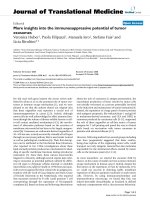
of aMR (see Figure 1):
aMR ≈ FR * nrMUs * RatioAreas (2)
Where RatioAreas = ratio between part of the muscle within
the electrode detection area and total muscle cross-section area
The detection area contains both skin and muscle tissue.
The skin part of the detection area (shaded in Figure 1) is
approximately 10%. Because MUs can only be located in
the muscle tissue, which is 90% of the detection area,
equation (2) becomes:
aMR ≈ FR * nrMUs * * 0.9
≈ FR * nrMUs * * 0.9
Where r
m
= muscle radius and r
e
= detection area radius
≈ FR * nrMUs * * 0.9
θ can be calculated with the law of cosine for the triangle
indicated in Figure 1 with dotted lines:
aMR ≈ FR * nrMUs * arccos *
0.9
Where d = thickness of the subcutaneous layer
With r
e
= 10 mm, r
m
= 20 mm and d = 2 mm this becomes:
DetectionArea
MuscleCrossSection
2
2
2
2
θ
π
π
π
∗ r
r
e
m
θ
π
r
r
e
m
2
2
rr rd
rd
r
r
me m
m
e
m
22 2 2
2
2
−− +
−+
∗
()
π
Table 1: Settings of parameters used in the simulation package
Sample frequency 2000 Hz
Signal duration 10 seconds
Muscle length 100 mm
Muscle radius 20 mm
Motor point location 60 mm
Maximal detection distance 10 mm
Electrode diameter 1.8 mm
Intracellular action potential duration 5 ms
Mean muscle fibre conduction velocity 4 m/s
Intracellular conductivity 1.010 S/m
Radial conductivity 0.063 S/m
Longitudinal conductivity 0.330 S/m
Motor unit radius Mean 4 mm, SD 0.2 mm
Journal of NeuroEngineering and Rehabilitation 2006, 3:15 />Page 4 of 13
(page number not for citation purposes)
aMR ≈ FR * nrMUs * 0.069 * 0.9
≈ 0.062 * FR * nrMUs
In summary, in simulation 1a, aMR is estimated by
FR*nrMUs and in simulation 1b by 0.062*FR*nrMUs.
In simulation 2, firing rate was varied in two conditions:
with 5 active MUs (simulation 2a) and with 10 active MUs
(simulation 2b). Each MU was assigned an individual fir-
ing rate; see Section 2.1.3. Mean firing rate was varied
from 8 to 20 pulses per second (pps). In these simula-
tions, all other variables were held constant so that varia-
tion in eMR could exclusively be related to variation in
one input variable.
In physiological circumstances, the number of MUs and
firing rate are not independent of each other. Therefore, in
simulation 3 these two variables were varied simultane-
ously to simulate an increasing force production. Differ-
ent authors have shown that rate coding mainly
contributes to force production at higher force levels
(above 30% of the maximal voluntary contraction force,
MVC), especially for large muscles [18,19]. Therefore, in
the first simulation steps only the number of MUs was
increased while in the later steps, both the number of MUs
and the mean firing rate were increased simultaneously
(see Table 2). The firing rate values were based on experi-
mental research by Conwit et al. [19], who investigated
average firing rate in relation to percentage of MVC.
The second set of simulations was directed at the influ-
ence of parameters related to peripheral muscle properties
and to the recording setup. These parameters do not affect
aMR, but they do affect the amplitude and frequency con-
tent of the signal. One of the most important peripheral
muscle properties is MU size, which is a combination of
the number of fibres per MU and their diameter. In simu-
lation 4, the influence of the number of fibers per MU
(range 5 – 1000) was investigated while in simulation 5
fiber diameter (40 – 100 μm) was addressed. According to
the Henneman principle [20], in physiological circum-
stances small MUs are always recruited first, and when
more force is required, larger MUs are recruited addition-
Table 2: Simulation protocols. Each row represents a simulation. The simulation number is shown in the left column; the settings of all
variables are shown in the other columns. In the third simulation, the number of MUs and firing rate are increased simultaneously in
steps; each row in the first two columns represents a step.
Simulation settings
Simulation
number
Number of MUs Firing rate (pps) Number of
fibers per MU
Fibre diameter
(μm)
Thickness
subcutaneou
s layer (mm)
SNR (dB)
1 a: 1–10 in steps of 1, 15–30 in
steps of 5
b: 12–120 in steps of 12, 120–
300 in steps of 60
Mean: 12, SD: 1 750 55 2 1000
2 a: 5
b: 10
Mean: 8 to 20 in
steps of 2, SD: 1
750 55 2 1000
3 1 10 750 55 2 1000
210
410
511
612
712.75
813.5
10 14
11 15
12 16
4 5 Mean: 12, SD: 1 5, 50, 100, 250,
400, 600, 750, 800,
900, 1000
55 2 1000
5 5 Mean: 12, SD: 1 750 Mean: 40 to 100 in
steps of 10, SD: 5
to 35 in steps of 5
21000
6 a: 5
b: 10
Mean: 12, SD: 1 750 55 0.5, 1, 2, 3, 4, 5 1000
7 a: 5
b: 10
c: 15
Mean: 12, SD: 1 750 55 2 3, 6, 10, 15,
20, 50, 100,
1000
Journal of NeuroEngineering and Rehabilitation 2006, 3:15 />Page 5 of 13
(page number not for citation purposes)
ally. To simulate this behaviour, the mean and the stand-
ard deviation of the distribution from which the mean
fibre diameter was drawn were increased simultaneously
(see Table 2).
Furthermore, in simulation 6 the influence of thickness of
the subcutaneous layer (range 0.1 – 5 mm) was evaluated
when 5 MUs (6a) and 10 MUs (6b) were active. Due to fil-
tering effects of the subcutaneous layer, the EMG signal is
attenuated [21] and the duration of the MUAPs may
become longer, which could lead to an increase in MUAP
superimposition. These effects may affect the performance
of the algorithm to detect MUAP shapes.
Finally, since the performance of the algorithm was
expected to depend on the signal to noise ratio (SNR) as
well, this variable was varied from 3 dB to 1000 dB in sim-
ulation 7. This simulation was performed with 5, 10 and
15 MUs (simulations 7a – c).
Simulation settings
See Table 2. In case the number of MUs was not varied
(simulations 2, 4–7), it was set to 5, 10 or 15. The default
value of SNR was set to 1000 dB, resembling a signal with-
out noise. The default number of fibres per MU was set to
750, which corresponds to the average MU size in the
biceps brachii [22]. Fiber diameter was set to 55 μm and
thickness of the subcutaneous layer to 2 mm.
When firing rate was kept constant (simulations 1, 4–7),
for each MU, its mean inter-pulse interval (IPI) was drawn
from a Gaussian distribution with a mean of 83.3 ms and
a standard deviation (SD) of 7 ms (corresponding to a
mean firing rate of 12 pps with an SD of 1 pps). The vari-
ation within a pulse train (belonging to one MU) was set
to ten percent.
The influence of fiber diameter was investigated in simu-
lation 5. For each MU, a mean fibre diameter was drawn
from a normal distribution (bounded at ± 3 SDs) with a
user-defined mean and SD. Next, the individual fibre
diameters within the MU were drawn from a normal dis-
tribution (bounded at ± 2 SDs) with the drawn fibre
diameter as mean and a SD of 1 μm (default setting of the
simulation package).
SNR could not be varied in the simulation package. There-
fore, Gaussian noise was added to the simulated signals
by using custom-made software written in Matlab (The
MathWorks, Inc., Natick, MA, USA).
Each step in the simulations was repeated three times and
outcome values were averaged to decrease the variability
introduced in the input parameters.
Experimental set-up
Subjects
The study was approved by the local medical ethics com-
mittee. Five subjects (three female, two male, mean (SD)
age 26.6 (2.70) years, weight 68.4 (10.9) kg, height 175.8
(11.3) cm, body-mass index (BMI) 22.1 (1.9) kg/m
2
)
without known disorders took part in this study. All sub-
jects gave their written informed consent.
General procedures
Subjects performed a stepwise increasing contraction con-
sisting of five force levels of 20 to 100 N in steps of 20 N.
The force levels were shown on a laptop screen and sub-
jects were instructed to keep the force level as constant as
Schematic representation of the muscle and the electrode detection areaFigure 1
Schematic representation of the muscle and the electrode
detection area. Upper circle indicates the electrode detec-
tion area, lower circle indicates the muscle and the subcuta-
neous layer. r
e
: radius of electrode detection area (10 mm),
r
m
: muscle radius (20 mm), d: thickness of the subcutaneous
layer (2 mm). The ratio between the part of the muscle
within the electrode detection area and total muscle cross-
section area was calculated for estimation of the number of
MUs that contribute to the EMG signal in relation to the
total number of MUs, located throughout the muscle. Dotted
lines indicate the triangle used for calculation of θ. Shaded
area indicates the part of the electrode detection area that
lies within the subcutaneous layer and does not contain MUs.
Journal of NeuroEngineering and Rehabilitation 2006, 3:15 />Page 6 of 13
(page number not for citation purposes)
possible for each step. Each level was maintained for ten
seconds. Between the levels, one second was allowed for
transition to the next level.
Subjects were seated on a chair that was adjusted in height
to prevent them from touching the floor with their feet.
The chair was attached to a frame that was fixed to the
wall. Two force transducers (Thermonobel, Karlskoga,
Sweden) were attached to the frame for measuring the
force from the trapezius muscle. The position of the force
sensors was adjusted to body size, such that the sensor
centre was located slightly above the acromion. In rest, the
force sensors were just not touching the subject. The force
signals were sampled with 1 kHz and digitised with a 16-
bits A/D converter, and stored on a laptop.
Subjects were instructed not to speak or move the head
during the recordings, to sit straight, and to keep their
hands rested in the lap. Subjects were not allowed to cross
their feet.
EMG recordings
EMG of the dominant upper trapezius was recorded using
a two-dimensional 16-channel electrode array (Helm-
holtz Institute for Biomedical Engineering, Technical Uni-
versity Aachen, Aachen, Germany). The array consisted of
four rows, the first and fourth containing three contact
points and the middle two containing five contact points.
The distance between the rows was 10 mm, as was the dis-
tance between the adjacent electrodes within a row. The
inter-electrode distance is relatively small in comparison
with conventional surface EMG measurements, which
increases the spatial selectivity.
Before electrode placement, the skin was cleaned using
abrasive paste. Electrodes were placed with the rows par-
allel to the line from the spinous process of the seventh
cervical vertebra (C7) to the acromion with the centre of
the electrode 2 cm lateral from the midpoint, in accord-
ance with the SENIAM recommendations [23]. A ground
electrode was placed on the wrist of the dominant side.
The monopolar signals were amplified 1000 times, sam-
pled at 4000 Hz and band-pass filtered (10–500 Hz) with
a custom made EMG amplifier (Helmholtz Institute for
Biomedical Engineering, Technical University Aachen,
Aachen, Germany). The signals were digitised using a 16
bit A/D-converter and stored on a laptop. Before the meas-
urement started, the signal quality was inspected visually.
Criteria for correct electrode placement were presence of
propagating MUAPs across the channels, similarity of the
MUAP shapes in all channels and absence of excessive
noise. Adjustments were made when necessary until sig-
nals with good quality could be obtained.
Data analysis
Monopolar signals with an inter-electrode distance of 10
mm from adjacent electrodes from the middle two rows
of the array were subtracted, resulting in two sets of four
single differential signals. For both sets, cross-correlation
between adjacent signals was calculated, resulting in three
values from each set. Adjacent signals are expected to
show a high degree of similarity when there are no arte-
facts present. The set with the highest average correlation
coefficient was therefore selected for further processing.
For the simulated signals, analogous to the experimental
signals, a set of four single differential signals was con-
structed by subtracting signals from adjacent electrodes.
For detection of MUAPs, a wavelet-based algorithm that
uses multi-channel information was applied ([12,24]).
The algorithm uses the continuous wavelet transform
(CWT) to identify shapes that are similar to a mother
wavelet. As mother wavelet, the first Hermite-Rodriguez
function was used. The CWT uses two parameters, being a
time shift (related to the location in time where a similar
shape occurred) and a scale factor that is related to the
amplitude and width of the wavelet. The CWT of each sin-
gle signal is calculated for a range of different values for
both parameters. The squared output of the CWT (ranging
from 0 to 1) is a measure for the similarity between the
mother wavelet and the signal at a certain time instant.
This output can be plotted in a three-dimensional graph
against the time instant and the scale factor, resulting in a
so-called scalogram.
The algorithm started with calculating the CWT for the
first channel. When the scalogram reached a maximum
that was higher than a user-defined threshold (set to 0.1
in this study), a candidate MUAP was found at the time
instant and scale factor corresponding to the maximum.
The algorithm then searched for candidate MUAPs that
were located in the surrounding channels within a time
delay corresponding to a conduction velocity between 2
and 8 m/s. When the candidate was present in a minimal
number of channels (set to 3 in this study), the candidate
was considered a MUAP. Then, the CWT was calculated
for the next channel. The algorithm cycled through the
channels in this way. Outputs of the algorithm were the
firing times and the corresponding MUAP shapes on each
channel. For more details, see [12,24].
From the firing instances, the number of MUAPs (result-
ing from all MUs together) was extracted for time win-
dows of one second. The mean value (across time) was
calculated and is reported as eMR. aMR is estimated by
multiplying the average firing rate with the number of
MUs.
Journal of NeuroEngineering and Rehabilitation 2006, 3:15 />Page 7 of 13
(page number not for citation purposes)
Root-mean-square values (RMS) were calculated from
each signal for time windows of one second. Values were
calculated for each channel and averaged both across
channels and across time.
The algorithms were implemented in Matlab software
(The MathWorks, Inc., Natick, MA, USA).
Results
Throughout the results section, eMR, aMR and RMS are
compared.
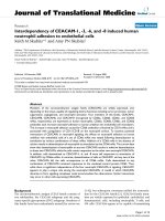
In Figure 2, an example of a simulated signal is shown for
10 active MUs, together with an example of an experimen-
tally recorded signal from the upper trapezius muscle at
100 N for comparison. The appearance of the simulated
signal is similar to the experimentally recorded signal. The
median frequency of the power spectrum of the simulated
signals (first channel) is 64.7 Hz, while that of the experi-
mental signal (first channel) is 63.5 Hz. When less active
MUs are simulated, individual MUAPs can easily be recog-
nised.
Determinants of MR
In Figure 3 (upper graphs), the relation between the
number of active MUs and both eMR and RMS when the
MUs are located within the detection area of the elec-
trodes is shown (simulation 1a). eMR increases with the
number of active MUs, but the percentage of detected
MUAPs decreases. Visual inspection of the signals under-
lines that this is related to the increasing occurrence of
superimpositions that are detected as single MUAPs. The
best fit of a second order polynomial trend line resulted in
an explained variance (squared Pearson's correlation coef-
ficient, r
2
) of 0.99 (p < 0.001).
RMS also increases with number of active MUs. The best
trend line was a square root relation which resulted in an
explained variance of 0.86 (p < 0.001).
Figure 3 also shows the relation between number of MUs
and both eMR and RMS when the location of the MUs was
not restricted to the detection area (simulation 1b, lower
graphs). The shape of the curve is similar as for simulation
1a, but the variability of the measurements is larger, as is
reflected in the somewhat lower explained variance: the
best fit was a second order polynomial trend line with an
explained variance of 0.91 (p < 0.001). RMS was best
approximated by a square root relation, with an explained
variance of 0.92 (p < 0.001).
In simulation 2 firing rate was simulated in two condi-
tions: 1) while 5 MUs are active, 2) while 10 MUs are
active. aMR increases linearly with firing rate in both situ-
ations, with a steeper slope when 10 MUs are active. eMR
increases linearly as well, but the slope of the curve is less
steep than for aMR. Fitting of a linear regression line
through the eMR curves resulted in a line with a slope of
2.18 and an intercept of 41.7 pps (r
2
= 0.96, p < 0.001) for
5 active MUs and a slope of 1.72 and an intercept of 16.6
pps (r
2
= 0.95, p < 0.0001) for 10 active MUs. The curve
for 10 active MUs is shifted to higher values than the curve
for 5 active MUs.
Figure 4 shows the behaviour of MR when increasing force
production is simulated as a combined increase of firing
rate and number of MUs. Both aMR and eMR increase
with simulated force. The increase is less for eMR than for
aMR, similar to the results of simulation 1 and 2.
Simulated signals with ten active MUs (upper graph) and experimentally recorded signal at a force level of 100 N (lower graph)Figure 2
Simulated signals with ten active MUs (upper graph) and
experimentally recorded signal at a force level of 100 N
(lower graph). Four single differential signals with 10 mm
inter-electrode distance, recorded parallel to the muscle fib-
ers are shown. Fibre direction is from innervation zone
(upper signal) to tendon (lower signal). Triangles indicate
detected MUAPs. A.u.: arbitrary units.
Journal of NeuroEngineering and Rehabilitation 2006, 3:15 />Page 8 of 13
(page number not for citation purposes)
In Figure 5, the influence of the determinants (number of
MUs and firing rate) on eMR in different conditions is
summarized. This figure provides an impression of the
stability of the relation between eMR and aMR in different
conditions. It shows that this relation is very similar for
the different simulations. The results from simulation 1b
(number of MUs with MUs distributed across the whole
muscle) deviate somewhat from the curve with slightly
lower eMR values, but the shape of the relation is similar.
For the pooled data, a logarithmic trend line resulted in an
explained variance of 0.94 while a second order polyno-
mial trend line resulted in r
2
= 0.92.
Parameters related to muscle properties and recording
setup
Except from the relation between RMS and thickness of
the subcutaneous layer, the relations between aMR, eMR
and RMS on one hand and number of fibers, fiber diame-
ter and thickness of the subcutaneous layer on the other
hand were best approximated with a linear fit. Linear
regression analysis was applied to estimate the coefficients
of the relations, and the explained variance. In contrast,
the relation between RMS and thickness of the subcutane-
ous layer was obviously non-linear. This relation could
best be approximated by a logarithmic relation. Explained
variance and coefficients were in this case estimated with
non-linear regression. Table 3 shows that number of fib-
ers, fiber diameter and thickness of the subcutaneous layer
explain a high percentage of variance of RMS values (r
2
>
0.94) but not of eMR and aMR (r
2
< 0.13). There is no sig-
nificant in- or decrease in aMR and eMR with these param-
eters, while RMS increases strongly with number of fibers
and fiber diameter. RMS decreases logarithmically with
thickness of the subcutaneous layer.
Relation between number of active MUs and both estimated MR and RMS in simulated conditionsFigure 3
Relation between number of active MUs and both estimated MR and RMS in simulated conditions. Upper graphs show the rela-
tions when MUs were restricted to be located within detection area of electrode. Lower graphs show the relations when MUs
were located throughout the whole muscle. Scales of the y-axis are the same in both RMS graphs.
0
10
20
30
40
50
60
70
80
0 5 10 15
Number of MUs
Estimated MR
(pps)
0 100 200 300
Number of MUs
RMS
(a.u.)
0 5 10 15
Number of MUs
RMS
(a.u.)
0
10
20
30
40
50
60
70
80
0 100 200 300
Number of MUs
Estimated MR
(pps)
Journal of NeuroEngineering and Rehabilitation 2006, 3:15 />Page 9 of 13
(page number not for citation purposes)
The aMR and corresponding eMR intercept values (β0)
that were found in simulations 4 tot 7 are consistent with
the relation between eMR and aMR as was found in simu-
lations 1 to 3 (Figure 5).
The influence of signal-to-noise ratio is shown in Figure 6
for 5, 10 and 15 active MUs. Obviously, aMR does not
change with SNR. For values lower than 15 dB, eMR
increases. In case of 5 active MUs, eMR is even higher than
aMR. RMS shows a similar behaviour.
Experimental results
The experimental results are reported in Figure 7. The rela-
tion between eMR and force is approximately linear,
although the increase in eMR flattens for the force levels
of 80 and 100 N. Individual second order polynomial
trend lines resulted in an average explained variance of
0.98 (range 0.97–0.99, p < 0.001). Linear trend lines
explained slightly less variance (mean r
2
= 0.94, range
0.88–0.97).
Discussion
The objective of this work was to explore to what extent
eMR, estimated from the surface EMG by using an elec-
trode array combined with an algorithm based on the
continuous wavelet transform, is suitable as a measure of
the input of the CNS to a muscle. For this purpose, we
investigated 1) the relation between eMR and the two
parameters with which the CNS controls muscle activity
(number of MUs and firing rate) and 2) the influence of
parameters related to muscle properties and to the record-
ing setup on eMR in comparison to RMS.
Determinants of MR
In simulations 1 to 3, the influence of the number of MUs
and firing rate on eMR were investigated. The high per-
centages of explained variance show that although eMR
diverges widely from aMR, eMR is strongly related to
number of active MUs (simulation 1) and firing rate (sim-
ulation 2), as well as to a combination of both (simula-
tion 3). The results from the different simulations are
consistent (Figure 5), which gives an indication of the sta-
bility of the relation between aMR and eMR. Increases in
the number of MUs and firing rate seem to be inter-
changeable; eMR only depends on the total number of
MUAPs per second.
The increase of eMR with number of MUs could well be
approximated (r
2
= 0.99) by a second order polynomial fit
with a negative coefficient for the quadratic term. This
indicates that the percentage of detected MUAPs decreases
when the number of MUs increases. Visual inspection of
the signals reveals that this is related to the occurrence of
superimpositions that are either not recognized, or
detected as single MUAPs. Assuming that the number of
superimpositions increases linearly, the percentage of
detected MUAPs decreases linearly as well, which would
indeed result in a second order polynomial relation. Sev-
eral algorithms aiming at full EMG decomposition con-
tain a method for resolving superimpositions [25-28]
These algorithms are developed for invasive needle or
wire recordings and are based on the shape differences
between MUAPs from different MUs. However, for surface
Relation between actual and estimated MR in different condi-tionsFigure 5
Relation between actual and estimated MR in different condi-
tions. Results of simulations with varying number of active
MUs, firing rate, and a combination of both. The relations
with number of MUs were simulated in two conditions: when
MUs were restricted to be located within the detection area
of the electrode and when MUs were located throughout the
whole muscle (indicated as "number of MUs (not limited)" in
the legend). The relations with firing rate were investigated
in case of 5 and 10 active MUs.
0
10
20
30
40
50
60
70
80
0 50 100 150 200 250 300 350 400
Actual MR (pps)
Estimated MR
(pps)
Number of MUs
Number of MUs (not limited)
Firing Rate 5 MUs
Firing Rate 10 MUs
Number of MUs and Firing rate
Actual and estimated MR in relation to simulated force pro-ductionFigure 4
Actual and estimated MR in relation to simulated force pro-
duction. To simulate an increasing force, the number of MUs
and their firing rate were increased simultaneously. See Table
2 for the parameter values at each step.
0
20
40
60
80
100
120
140
160
180
200
12345678910
simulation step
MUAP Rate
(pps)
actual MR
estimated MR
Journal of NeuroEngineering and Rehabilitation 2006, 3:15 />Page 10 of 13
(page number not for citation purposes)
EMG recordings, the MUAP shapes from different MUs
are rather similar. Other approaches to resolve superim-
positions such as algorithms based on independent com-
ponent analysis [29,30], that do not necessarily rely on
the occurrence of temporally isolated MUAPs in the signal
may prove to be more successful.
In order to make a reliable estimate of aMR, MUs were
restricted to be located within the detection area. When
the location of the MUs was not restricted, the variability
of both RMS and eMR was higher. Probably, part of this
variability is related to errors in the estimate of the
number of MUs that contribute to the signal. MUs may
partly lie within the detection area and it depends on the
location of the center of the MU whether it is included in
the estimate of the number of MUs or not. Furthermore,
contribution of parts of MUs is likely to increase back-
ground activity. However, despite the increased variabil-
ity, the shape of the relation between eMR and number of
MUs was the same for simulations 1a and 1b. Thus, the
restriction of the location of MUs to the detection area of
the electrode had a rather limited effect.
In conclusion, the simulation results show that eMR con-
siderably diverges from aMR. This implies that eMR can-
not directly be used to estimate the true number of
MUAPs in the EMG signal. However, the relation between
eMR and aMR is rather stable in different conditions and
eMR is strongly related to the number of MUs and firing
rate.
Parameters related to muscle properties and recording
setup
In contrast to RMS, eMR was not affected by number of
fibers per MU, fiber diameter and thickness of the subcu-
taneous layer. This underlines that eMR specifically
reflects parameters related to the input of the CNS to the
muscle, whereas RMS also depends on peripheral muscle
Influence of signal to noise ratio on estimated MRFigure 6
Influence of signal to noise ratio on estimated MR. Simulations were performed in case of 5, 10 and 15 active MUs.
40
60
80
100
120
140
160
180
200
0 1020304050
signal to noise ratio (dB)
MUAP
Rate (pps)
actual MR 5 MUs
estimated MR 5 MUs
actual MR 10 MUs
estimated MR 10 MUs
actual MR 15 MUs
estimated MR 15 MUs
0
5
10
15
20
25
-10 10 30 50
signal to noise ratio (dB)
RMS (uV)
RMS 5 MUs
RMS 10 MUs
RMS 15 MUs
Table 3: Influence of peripheral properties on aMR, eMR and RMS. Linear regression was applied for estimation of the percentage of
explained variance (r
2
) and of the intercept β0 and slope β1. The relation between RMS and thickness of the subcutaneous layer could
best be approximated with a logarithmic relation. Nonlinear regression was performed to estimate the coefficients of this relation.
aMR (pps) eMR (pps) RMS (a.u.)
β0 β1r
2
p β0 β1r
2
p β0 β1r
2
p
Number of fibers 62.2 -0.0011 0.11 0.35 41.4 0.0027 0.13 0.31 1.15 0.14 0.96 0.001
Fiber diameter 57.2 0.018 0.046 0.65 37.0 0.048 0.11 0.47 118 4.5 0.97 0.001
Thickness of subcutaneous layer 5 MUs 59.9 0.072 0.038 0.57 42.5 0.24 0.062 0.46 132 -37 0.94 0.001
Thickness of subcutaneous layer 10 MUs 122 -0.36 0.073 0.42 61.3 0.31 0.027 0.63 195 -63 0.98 0.001
Journal of NeuroEngineering and Rehabilitation 2006, 3:15 />Page 11 of 13
(page number not for citation purposes)
and subcutaneous layer properties. In a previous study
differences between cases with chronic neck-shoulder
pain and healthy controls were found in eMR, while RMS
did not show any differences [13]. The sensitivity of RMS
for peripheral properties, that the present findings con-
firm, was suggested to be a cause of this. The influence of
peripheral properties may have masked subtle differences
in motor control. The sensitivity of RMS for peripheral
properties may be decreased by normalising the RMS val-
ues to an individual's RMS value during MVC, as is often
done in experimental studies. However, especially in sub-
jects with pain or fear of pain, it may be difficult to assess
an individual's maximal capacity reliably.
Two aspects of MU size were investigated: the number of
fibers per MU and fiber diameter. Both parameters did not
affect eMR, while they showed a linear relation with RMS.
Because in physiological circumstances, additionally
recruited MUs in general will be larger [20], MU size also
affects the relation between RMS and force. The sensitivity
of RMS for peripheral properties in general may lead to a
higher inter-subject variability for RMS than for eMR.
The percentage of detected MUAPs remained constant
when fiber diameter was varied. By increasing the mean
muscle fibre diameter within a MU as well as the width of
the distribution of mean fibre diameter across MUs simul-
taneously, the recruitment of larger MUs was simulated
while the smaller MUs remained present in the signal. In
this way it was shown that small MUAPs are still detected
in the presence of large MUAPs. This is in agreement with
simulation results of Gazzoni et al. [12], who also
reported that both small and large MUs were simultane-
ously detected.
It was shown that estimation of MR is hampered when the
SNR becomes lower than 15 dB, independent of the
number of active MUs. In this case, apparently noise is
generating false positives. RMS was also over-estimated
for lower SNRs. This implies that the SNR in experimental
conditions should be higher than 15 dB. In the experi-
mental part of this study SNR (estimated from the signal
variance during contraction divided by the signal variance
during rest) typically ranged from 40 to 100 dB for the
applied force range, indicating that noise did not hamper
the estimation of MR.
Experimental results
The experimental results showed strong, second order
polynomial individual relations between eMR and con-
traction force (0.97 < r
2
< 0.99). In comparison, individual
linear relations between RMS and shoulder elevation
torque with explained variances of 88–97% have been
reported [31].
The maximal force that was measured was 100 N, which
corresponded to an eMR of approximately 40 pps. From
Figure 5 can be seen that in the range from 0 to 40 pps, the
increase of eMR is approximately linear. A force of 100 N
corresponds to 25–30% of MVC, that was 357 N for
healthy subjects in the same experimental setup [32]. For
higher force levels, the eMR-force curve will probably flat-
ten, due to the increased occurrence of superimpositions.
Absolute rather than relative force levels were used in this
study, since in daily life conditions, experienced loads are
also not scaled to an individual's capacity. Relative force
levels are often used to decrease inter-subject variability.
When the force levels would have been normalised, the
relation between eMR and force might have been even
stronger.
The number of MUs that contribute to the signal is
strongly dependent on the spatial selectivity of the record-
ing system [5]. Selection of the recording system involves
a trade-off between representation of all MUs and optimal
MR estimation. The single differential configuration with
the relatively small inter-electrode distance (10 mm) that
was applied for this study appeared to be suitable for the
range of investigated force levels. For higher force levels,
MR estimation might improve by applying a more spa-
tially selective filter, which can be reached with a more
selective electrode configuration or with a smaller inter-
electrode distance. When recordings are made with a two-
dimensional array, as was done in this study, the spatial
selectivity can be increased by using the Laplacian config-
Relation between estimated MR and force in experimental conditions during a step contraction of the trapezius muscle (force levels from 20 to 100 N)Figure 7
Relation between estimated MR and force in experimental
conditions during a step contraction of the trapezius muscle
(force levels from 20 to 100 N). Mean values of 5 subjects
are shown. Bars show inter-subject standard errors of the
mean both in force and estimated MR.
0
5
10
15
20
25
30
35
40
45
50
0 20 40 60 80 100 120
Force (N)
Estimated MR
(pps)
Journal of NeuroEngineering and Rehabilitation 2006, 3:15 />Page 12 of 13
(page number not for citation purposes)
uration [7]. With linear electrode arrays [8], the inter-elec-
trode distance could be shortened.
Methodological aspects
MR is a combination of the number of active MUs and
their firing rates and does not give information about each
of these variables separately. Many research groups are
working on algorithms for complete EMG decomposition
(e.g. [12,33-35]). In most algorithms, the first step of
decomposition is the detection of MUAPs in the signal.
The second step consists of the assignment of the detected
MUAPs to the MU that generated them (classification).
Other algorithms are based on higher-order statistical fea-
tures of the EMG signals [29].
Complete decomposition would result in clinically rele-
vant information that can easily be interpreted. However,
most methods are only able to decompose very few MUs
(about 5) completely from surface EMG signals. Further-
more, decomposition of MUs with small MUAP ampli-
tude is difficult, whereas the results of simulation 5 show
that detection of small MUAPs is possible even in the pres-
ence of big MUAPs.
Zhou et al. also developed a method for MUAP counting
based on template matching [10]. They obtained MUAP
templates of each MU from spike-triggered averaging of
the surface EMG signal by using decomposed intramuscu-
lar EMG signals as trigger. These templates were then used
to generate a simulated EMG signal. Their MUAP counting
algorithm was able to estimate MR reliably up to 100 pps
from these signals, which seems a better performance
than that of the algorithm we applied. For higher values,
the performance of the algorithm also decreased. It
should be taken into account that the templates used for
generation of simulated signals were used for detection as
well in the algorithm of Zhou et al. Since such templates
are not a priori known in an experimental setting without
intramuscular recordings, the performance of the algo-
rithm in such conditions remains to be investigated.
Conclusion
The simulations showed rather stable, monotonously
increasing relations between eMR and both number of
active MUs and firing rate. In contrast to RMS, eMR is
hardly influenced by the number of fibers per MU, fiber
diameter and thickness of the subcutaneous layer. eMR
therefore seems to specifically reflect input from the cen-
tral nervous system to the muscle while it is not affected
by peripheral aspects. Experimental data showed a strong,
approximately linear relation between eMR and force.
Although the actual number of MUAPs in the signal can-
not be accurately extracted with the present method, eMR
seems to be a suitable non-invasive tool to study the input
of the central nervous system to the muscle at low contrac-
tion levels.
Competing interests
The author(s) declare that they have no competing inter-
ests.
Authors' contributions
LK participated in the conception and design of the study,
carried out the experimental part of the study, analysed
and interpreted the data and drafted the manuscript. HH
participated in the conception and design of the study,
helped in interpreting the data and revised the manu-
script. All authors read and approved the final manu-
script.
Acknowledgements
The authors would like to thank Ms. J.C. van den Noort for her contribu-
tion to the simulations and Dr. J.Y. Hogrel for generously providing us with
a new version of the SiMyo software. This work has been supported by the
European Shared Cost project NEW (QLRT-2000-00139).
References
1. Winter DA, Yack HJ: EMG profiles during normal human walk-
ing: stride-to-stride and inter-subject variability. Electroen-
cephalogr Clin Neurophysiol 1987, 67:402-11.
2. Mathiassen SE, Aminoff T: Motor control and cardiovascular
responses during isoelectric contractions of the upper trape-
zius muscle: evidence for individual adaptation strategies.
Eur J Appl Physiol Occup Physiol 1997, 76:434-44.
3. Bilodeau M, Schindler-Ivens S, Williams DM, Chandran R, Sharma SS:
EMG frequency content changes with increasing force and
during fatigue in the quadriceps femoris muscle of men and
women. J Electromyogr Kinesiol 2003, 13:83-92.
4. Farina D, Madeleine P, Graven-Nielsen T, Merletti R, Arendt-Nielsen
L: Standardising surface electromyogram recordings for
assessment of activity and fatigue in the human upper trape-
zius muscle. Eur J Appl Physiol 2002, 86:469-78.
5. Disselhorst-Klug C, Silny J, Rau G: Improvement of spatial reso-
lution in surface-EMG: a theoretical and experimental com-
parison of different spatial filters. IEEE Trans Biomed Eng 1997,
44:567-74.
6. Zwarts MJ, Stegeman DF: Multichannel surface EMG: basic
aspects and clinical utility. Muscle Nerve 2003, 28:1-17.
7. Farina D, Schulte E, Merletti R, Rau G, Disselhorst-Klug C: Single
motor unit analysis from spatially filtered surface electromy-
ogram signals. Part I: spatial selectivity. Med Biol Eng Comput
2003, 41:330-7.
8. Merletti R, Farina D, Gazzoni M: The linear electrode array: a
useful tool with many applications. J Electromyogr Kinesiol 2003,
13:37-47.
9. Blok JH, van Dijk JP, Drost G, Zwarts MJ, Stegeman DF: A high-den-
sity multichannel surface electromyography system for the
characterization of single motor units. Rev Sci Instrum 2002,
73:1887-1897.
10. Zhou P, Rymer WZ: MUAP number estimates in surface EMG:
template-matching methods and their performance bound-
aries. Ann Biomed Eng 2004, 32:1007-15.
11. Roeleveld K, Stegeman DF, Vingerhoets HM, Van Oosterom A: The
motor unit potential distribution over the skin surface and
its use in estimating the motor unit location.
Acta Physiol Scand
1997, 161:465-72.
12. Gazzoni M, Farina D, Merletti R: A new method for the extrac-
tion and classification of single motor unit action potentials
from surface EMG signals. J Neurosci Methods 2004, 136:165-77.
13. Kallenberg LA, Hermens HJ: Motor unit action potential rate
and motor unit action potential shape properties in subjects
with work-related chronic pain. Eur J Appl Physiol 2006, 96:203-8.
Publish with BioMed Central and every
scientist can read your work free of charge
"BioMed Central will be the most significant development for
disseminating the results of biomedical research in our lifetime."
Sir Paul Nurse, Cancer Research UK
Your research papers will be:
available free of charge to the entire biomedical community
peer reviewed and published immediately upon acceptance
cited in PubMed and archived on PubMed Central
yours — you keep the copyright
Submit your manuscript here:
/>BioMedcentral
Journal of NeuroEngineering and Rehabilitation 2006, 3:15 />Page 13 of 13
(page number not for citation purposes)
14. Duchene J, Hogrel JY: A model of EMG generation. IEEE Trans
Biomed Eng 2000, 47:192-201.
15. Nandedkar SD, Stalberg E: Simulation of single muscle fibre
action potentials. Med Biol Eng Comput 1983, 21:158-65.
16. Roeleveld K, Stegeman DF, Vingerhoets HM, Van Oosterom A:
Motor unit potential contribution to surface electromyogra-
phy. Acta Physiol Scand 1997, 160:175-83.
17. Barkhaus PE, Nandedkar SD: Recording characteristics of the
surface EMG electrodes. Muscle Nerve 1994, 17:1317-23.
18. Kukulka CG, Clamann HP: Comparison of the recruitment and
discharge properties of motor units in human brachial biceps
and adductor pollicis during isometric contractions. Brain Res
1981, 219:45-55.
19. Conwit RA, Stashuk D, Tracy B, McHugh M, Brown WF, Metter EJ:
The relationship of motor unit size, firing rate and force. Clin
Neurophysiol 1999, 110:1270-5.
20. Henneman E, Somjen G, Carpenter DO: Functional significance of
cell size in spinal motoneurons. J Neurophysiol 1965, 28:560-80.
21. Nordander C, Willner J, Hansson GA, Larsson B, Unge J, Granquist
L, Skerfving S: Influence of the subcutaneous fat layer, as meas-
ured by ultrasound, skinfold calipers and BMI, on the EMG
amplitude. Eur J Appl Physiol 2003, 89:514-9.
22. Buchthal F: The general concept of the motor unit. Neu-
romuscular disorders. Res Publ Assoc Res Nerv Ment Dis 1961,
38:3-30.
23. Hermens HJ, Freriks B, Disselhorst-Klug C, Rau G: Development of
recommendations for SEMG sensors and sensor placement
procedures. J Electromyogr Kinesiol 2000, 10:361-74.
24. Farina D, Fortunato E, Merletti R: Noninvasive estimation of
motor unit conduction velocity distribution using linear elec-
trode arrays. IEEE Trans Biomed Eng 2000, 47:380-8.
25. Stashuk D: EMG signal decomposition: how can it be accom-
plished and used? J Electromyogr Kinesiol 2001, 11:151-73.
26. McGill KC, Lateva ZC, Marateb HR: EMGLAB: An interactive
EMG decomposition program. J Neurosci Methods 2005,
149:121-33.
27. Loudon GH, Jones NB, Sehmi AS: New signal processing tech-
niques for the decomposition of EMG signals. Med Biol Eng
Comput 1992, 30:591-9.
28. Zennaro D, Wellig P, Koch VM, Moschytz GS, Laubli T: A software
package for the decomposition of long-term multichannel
EMG signals using wavelet coefficients. IEEE Trans Biomed Eng
2003, 50:58-69.
29. Nakamura H, Yoshida M, Kotani M, Akazawa K, Moritani T: The
application of independent component analysis to the multi-
channel surface electromyographic signals for separation of
motor unit action potential trains: part I-measuring tech-
niques. J Electromyogr Kinesiol 2004, 14:423-32.
30. Nakamura H, Yoshida M, Kotani M, Akazawa K, Moritani T: The
application of independent component analysis to the multi-
channel surface electromyographic signals for separation of
motor unit action potential trains: part II-modelling inter-
pretation. J Electromyogr Kinesiol 2004, 14:433-41.
31. Louhevaara V, Long A, Owen P, Aickin C, McPhee B: Local muscle
and circulatory strain in load lifting, carrying and holding
tasks. Int J Ind Ergon 1990, 6:151-162.
32. Schulte E, Kallenberg LA, Christensen H, Disselhorst-Klug C, Her-
mens HJ, Rau G, Sogaard K: Comparison of the electromyo-
graphic activity in the upper trapezius and biceps brachii
muscle in subjects with muscular disorders: a pilot study. Eur
J Appl Physiol 2006, 96:185-93.
33. Kleine BU, Blok JH, Oostenveld R, Praamstra P, Stegeman DF: Mag-
netic stimulation-induced modulations of motor unit firings
extracted from multi-channel surface EMG. Muscle Nerve
2000, 23:1005-15.
34. Chauvet E, Fokapu O, Hogrel JY, Gamet D, Duchene J: Automatic
identification of motor unit action potential trains from elec-
tromyographic signals using fuzzy techniques. Med Biol Eng
Comput 2003, 41:646-53.
35. Holobar A, Zazula D: Correlation-based decomposition of sur-
face electromyograms at low contraction forces. Med Biol Eng
Comput 2004, 42:487-95.