Nuclear Power Control, Reliability and Human Factors Part 3 pdf
Bạn đang xem bản rút gọn của tài liệu. Xem và tải ngay bản đầy đủ của tài liệu tại đây (513.83 KB, 30 trang )
3
Nuclear Power Plant
Instrumentation and Control
H.M. Hashemian
Analysis and Measurement Services Corp.
United States
1. Introduction
Installed throughout a nuclear power plant, instrumentation and control (I&C) is an
essential element in the normal, abnormal and emergency operation of nuclear power plants
(International Atomic Energy Agency [IAEA], n.d.). Through their equipment, modules,
sensors, and transmitters, I&C systems measure thousands of variables and processes the
data to activate pumps, valves, motors, and other electromechanical equipment that control
the plant. The I&C system senses basic physical parameters, monitors performance,
integrates information, and makes automatic adjustments to plant operations to keep
process variables within the plant design limits. By reacting appropriately to failures and
abnormal events, I&C ensures the plant’s safety and efficient production of power (U.S.
Nuclear Regulatory Commission [U.S. NRC], 2011).
All of these roles can be reduced to three basic functions (IAEA, 1999). First, as the plant’s
nervous system, I&C provides plant operators with accurate and relevant information so
they can make the appropriate actions during normal as well as abnormal operation.
Second, I&C provides plant operators with the capacity to exercise automatic control over
the plant and its associated systems so they can take whatever actions are needed to
maintain efficient and safe operation. Finally, I&C serves the critical function of protecting
the plant from faults in the system or errors made by the operator as well as abnormal or
extreme external events that threaten the plant’s operation. More specifically, I&C should
enable the plant to operate safely for an extended period without operator intervention
following an accident (IAEA, 1999).
Nuclear plant I&C systems must be accurate to properly sense and communicate the process
variables and reasonably fast to provide timely display, adjustment, and protection against
upsets in both the main plant and its ancillary systems. For example, temperature sensors
such as resistance temperature detectors (RTDs), which are key elements in the safety
system instrumentation of nuclear power plants, may be expected to provide 0.1 percent
accuracy and respond to a step change in temperature in less than 4 seconds.
Nuclear plant I&C is more complex and varied than the control instrumentation in other
industrial applications because of the special nature of nuclear power. A nuclear plant’s
production must remain continuous because of its high capital costs, direct access to and
control over the nuclear plant’s reactor is impossible, and the potential risks of nuclear energy
production require greater redundancy and reliability in plants’ control infrastructure (IAEA,
1999). Although I&C is a relatively small component in a typical plant’s maintenance and
Nuclear Power – Control, Reliability and Human Factors
50
capital upgrade budget, its impact on the plant’s safety, reliability, and performance is
preeminent (Hurst 2007). For example, assuming that a 1000 MWe plant has a daily operating
revenue of about $2 million per day, a loss in power production level of even 1 percent can
quickly amount to millions of dollars in lost revenue.
Some 10,000 sensors and detectors and 5,000 kilometers of I&C cables—representing a total
mass of 1,000 tons—comprise the I&C system of a typical nuclear plant unit, including up to
20 neutron detectors, 60 RTDs, as many as 100 thermocouples, and 500 to 2,500 pressure
transmitters (IAEA, n.d.; Hashemian, forthcoming). Categorized by function, I&C
components consist of:
Sensors that interact with the plant’s physical processes to measure process variables
such as temperature, pressure and flow as well as control, regulation, and safety
components that process the sensors’ data.
Communication infrastructure—wires and cables, fiber-optic and wireless networks,
digital data protocols—that move sensor and control data through the I&C system.
Human-system interfaces such as displays that enable human plant operators to
monitor and respond to the continual flow of I&C data.
Surveillance and diagnostic systems that monitor sensor signals for abnormalities.
Actuators such as valves and motors that physically operate the plant’s control and
safety components to adjust physical processes so the plant’s performance is optimized
for efficiency and safety or, if needed, shut down.
Actuator status indicators that visually reflect automatic or manual control actions, such
as the switching on or off of a motor or the opening or closing of a valve (IAEA, n.d.).
2. Important I&C components
Nuclear plant instrumentation can generally be classified into the following four categories:
Nuclear: instruments that measure nuclear processes or reactor power, such as neutron
flux density.
Process: instruments that measure non-nuclear processes such as reactor pressure, coolant
or pressurizer level, steam flow, coolant temperature and flow, containment pressure, etc.
Radiation monitoring: instruments that measure radiation, for example, in monitoring
radiation in steam lines, gas effluents, and radiation at the plant site.
Special: Instruments encompassing all other applications, such as for measuring
vibration, hydrogen concentration, water conductivity and boric acid concentration or
meteorological, seismic, or failed fuel detection applications (IAEA, 1999).
The variety of I&C components and applications notwithstanding, temperature, pressure,
level, flow, and neutron flux remain the most important and safety-critical measurements
for the control and safety protection of nuclear reactors. The heart of each of these
measurements is the sensor itself the most important component in an instrument channel
and the one that usually resides in the harsh environment of the field (Hashemian, 2007).
Despite the accelerating advances in I&C technology (to be discussed in the next section),
the basic mechanism of measurement used by these sensors has not changed significantly
since the earliest nuclear plants. Today, temperature, pressure, level, flow, and neutron flux
are still primarily measured using conventional sensors such as resistance temperature
detectors (RTDs), thermocouples, capacitance cells, bellows, force-balance sensors, and
conventional neutron detectors although some advances have been made in developing new
neutron detectors for nuclear power plants (Hashemian, 2009a).
Nuclear Power Plant Instrumentation and Control
51
The control and safety of nuclear power plants depend above all on temperature and
pressure (including differential pressure to measure level and flow) instrumentation—the
two most ubiquitous instrument types in a typical nuclear power plant process. In
pressurized water reactor (PWR) plants, RTDs are the main sensors for primary system
temperature measurement. RTDs are thermal devices that contain a resistance element
referred to as the sensing element. Two groups of RTDs are typically used in nuclear power
plants: direct immersion (or wet-type) and thermowell mounted (or well-type). The
resistance of the sensing element changes with temperature, and therefore by measuring the
resistance, one can indirectly determine the temperature. The number of RTDs in a nuclear
power plant depends on the plant design and its thermal hydraulic requirements. For
example, PWR plants have up to 60 safety-related RTDs while heavy water reactors such as
Candu plants have several hundred RTDs.
Pressure transmitters are the next most common I&C component. A pressure transmitter
may be viewed as a combination of two systems: a mechanical system and an electronic
system. The pressure transmitter’s mechanical system contains an elastic sensing element
(diaphragm, bellows, Bourdon tube, etc.) that flexes in response to pressure applied. The
movement of this sensing element is detected using a displacement sensor and converted
into an electrical signal that is proportional to the pressure. Typically, two types of pressure
transmitters are used in most nuclear power plants for safety-related pressure
measurements. These are referred to as motion-balance and force-balance, depending on
how the movement of the sensing element is converted into an electrical signal.
A nuclear power plant generally contains about 400 to 1200 pressure and differential
pressure transmitters to measure the process pressure, level, and flow in its primary and
secondary cooling systems. The specific number of transmitters used in a plant usually
depends on the type and design of the plant. For example, the number of transmitters used
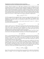
in PWRs depends on the number of reactor coolant loops. Figure 1 illustrates a typical
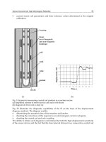
process instrumentation channel in a nuclear power plant.
Fig. 1. Typical Instrumentation Channel in Nuclear Power Plant (R = resistance; V = voltage;
I = current).
Nuclear Power – Control, Reliability and Human Factors
52
3. Evolution of I&C
The evolution of I&C has been marked by three generational shifts. In the first, analog
technology was used for instrumentation, and mechanical relay-based equipment was used
for control of discrete processes. The second generation of I&C was marked by the use of
discrete or integrated solid-state equipment for both instrumentation and control. The
emergence of the microprocessor in the late 1970s made possible the replacement of
mechanical relays by programmable logic controllers (PLCs). PLCs were initially used in
non-nuclear applications in nuclear plants, but their evolving ability to handle large
volumes of data, perform mathematical calculations, execute continuous process control,
and communicate with computers brought them into plants’ nuclear applications. The third
generation of I&C is digital, to be discussed in the next section.
One of the key forces driving the evolution of I&C has been the obsolescence of analog
equipment. A second driver has been technological: new information, electronic, display,
and digital technologies seem tailor made for the NPP I&C environment, where complexity
rules, automation is essential, and high initial infrastructure cost can be rationalized (IAEA,
1999).
Though sensor technology itself has not changed significantly, other I&C systems
have—perhaps more so than any other area of nuclear power plant science, offering
quantum functionality and performance improvements.
A third driver has been accidents, like Three Mile Island, Chernobyl, and Fukushima, which
force I&C system designers to reevaluate operating principles, system robustness and safety
margins, and accident probability assumptions. For example, both Three Mile Island and
Fukushima underscored the critical role of I&C signals in enabling operators to understand
the nature of the accident they are facing. On a general level, Three Mile Island helped
stimulate new research and development into signal validation, ultimately spawning the
discipline of on-line monitoring (to be discussed later in this chapter). Specifically, Three
Mile Island led directly to the adoption of safety parameter display systems. Both Chernobyl
and Fukushima forced I&C designers to focus more on analyzing the potential occurrence of
very rare events that would once have been considered non-‘design basis events’ so their
consequences might be mitigated.
A fourth driver of changes in I&C has been economic. Enhanced I&C means greater
knowledge of and control over plant conditions and therefore greater leeway in pushing
plant operating limits and extending uptime. More in-core instrumentation, redundant and
diverse instrumentation providing deeper comparative operational databases, and
enhanced qualification, calibration and maintenance have enabled plants to uprate their
power profiles without sacrificing safety margins (IAEA, 1999).
Because the cost of building new plants is so high, regulatory hurdles are so substantial, and
political resistance to nuclear power so significant, few new plants have been built. Instead,
existing plants are relicensed for extended lives far beyond their original design
assumptions. Nuclear power plants that operate for 60 years, for example, live through three
generations of I&C evolution (the qualified life of most nuclear plant pressure transmitters
and RTDs is typically about 20 years, although most properly maintained pressure
transmitters last longer than 20 years) (IAEA, n.d.).
In the mid-1980s, the nuclear industry
began to talk about aging and obsolescence in analog I&C equipment (Hashemian, 2009a).
In
this plant-life extension climate, enhanced, digital I&C became a way to offset the plant’s
age by giving operators new eyes and ears for staying on top of the continuing aging-
Nuclear Power Plant Instrumentation and Control
53
induced degradation of the plant. New fatigue monitoring and ‘condition limitation’
systems have made it possible to minimize disturbances and smooth out transients (IAEA,
1999).
Typically, plants will replace I&C in steps or modularly, swapping out a discrete
analog control system with a digital one, but retaining the existing field cabling, sensors,
and actuators (IAEA, 1999).
I&C system advances as a result of these drivers have produced a significant improvement
in plant capacity factor, outage time duration, personnel radiation exposure, power uprates,
and operational efficiency (Hashemian 2009b). However, it remains the case today that the
bulk of I&C systems used to monitor and control existing NPPs use analog process
technology developed in the 1950s and 1960s (IAEA, 1999).
4. Emergence of digital I&C
Digital I&C evolved from microprocessor-based PLCs and plant process-monitoring
computers (IAEA, 1999). Because they can be programmed to perform complex tasks,
microprocessors quickly replaced analog relays and spawned new applications in plant
monitoring and control systems, including graphical display interfaces so human operators
could observe and interact with the I&C system (IAEA, 1999).
The first protection systems
using digital technology, known as “core protection calculators,” were implemented on
combustion engineering designed reactors in the late 1970s (Bickel, 2009). In the 1980s,
digital technology was integrated into control systems for NPPs’ auxiliary subsystems.
Digital relays and recorders, smart transmitters, and distributed control systems (DCSs)
were implemented primarily in non-safety systems such as feedwater control, main turbine
control, and recirculation control (U.S. NRC, 2011; IAEA, 1999).
By the 1990s, microprocessors were being used for data logging, control, and display for
many nonsafety-related functions (U.S. NRC, 2011).
In 1996, the first fully digitalized I&C
system was integrated into Japan’s Kashiwazaki-Kariwa Unit 6 advanced boiling-water
reactor (ABWR), followed by Kashiwazaki-Kariwa Unit 7 in Japan (U.S. NRC, 2011;
Hashemian 2009a).
In the 2000s, all-digital I&C systems for both safety-related systems and
safety-critical systems were implemented worldwide (IAEA, 1999). For example, France, the
United Kingdom, Korea, and Sweden, among other countries, implemented digital I&C
systems in their nuclear power plants (U.S. NRC, 2011; Hashemian 2009a).
Today, about 40%
of the world’s operating power reactors in almost all of the thirty nations with operating
NPPs have been upgraded to some level of digital I&C. Ten percent of such installations
have occurred at new reactors, with the rest involving upgrades at existing reactors (IAEA,
n.d.).
Since 1990, all of the reactors under construction worldwide have some digital I&C
components in their control and safety systems (IAEA, n.d.).
Today, control panel instruments such as controllers, display meters, and recorders
are mostly digital. Most diagnostic and measuring equipment is digital, and increasingly
common digital transducer transmitters now offer so-called smart features like automatic
zeroing and calibration (IAEA, 1999).
Similarly, digital I&C systems like Westinghouse’s
Eagle 21, Common Q, and Ovation systems, Areva Nuclear Power’s Teleperm XS,
the Triconix Company’s TRICON system and Rolls Royce's Spinline are available for
retrofitting implementation on existing plants’ safety-related applications or in new
all-digital plants (U.S. NRC, 2011; Hashemian 2009a; IAEA, 2008).
The advanced boiling
water reactor (ABWR) plants built in Japan for more than a decade all use fully integrated
digital I&C systems for both safety-related and nonsafety-related plant control
Nuclear Power – Control, Reliability and Human Factors
54
and protection (Hurst 2007). Finally, the new reactor designs that have already
won certification (including the AP1000, System 80+, and ABWR) will make extensive use
of digital I&C (Oak Ridge National Laboratory [ORNL], 2007). To satisfy the demanding
operational environments of new designs, ranging from high temperatures to
high neutron flux (not to mention the post-Fukushima demands for I&C that can
survive “beyond design basis” conditions), advanced and in many cases digital sensors,
detectors, transmitters, and data transmission lines will continue to be needed (IAEA,
n.d.).
4.1 Benefits of digital
The attractions of digital I&C are many. First, by minimizing the number of analog circuits
required to perform an I&C measurement, digital processing reduces the potential
interference (noise) and drift that result from using multiple analog circuits. This makes
possible more accurate or precise measurements, which can be further refined through
digital data processing programs (IAEA, 1999; ORNL, 2007; Lipták, 2006).
Second,
measurement parameters can be much more easily modified with digital systems than with
analog systems. In contrast to the physical reconfiguration of an analog device, modifying
digital I&C merely requires loading a different program, which greatly enhances versatility.
Shifting functionality from hardware to software in this way means quicker installation of
I&C components (IAEA, 1999; ORNL, 2007; Lipták, 2006). Third, the increasingly
miniaturized integrated circuits in digital I&C offer substantial processing power relative to
device size, greatly reducing the space required for I&C equipment. Fewer and smaller
devices capable of transmitting higher concentrations of data using multiplexing also
translates into minimized cabling needs. Both the number and quality of I&C links in a plant
can be increased (IAEA, 1999; ORNL, 2007).
Fourth, digital technology’s processing power
means more complex functional capabilities for I&C, from on-line power density limit
computation and dead-time and temperature measurement correction to highly specifiable
and versatile signal filtering (IAEA, 1999).
Fifth, by offering greater automation possibilities,
digital I&C minimizes the need for human intervention, thus minimizing the possibility of
human error. Sixth, because digital I&C systems can perform automatic self-testing much
more easily than analog systems, they reduce maintenance costs and improve reliability
through continuous monitoring capability. Such self-testing functionality greatly aids in
analyzing system faults (IAEA, 1999).
4.2 Emerging sensors for digital I&C
Although the core technology of nuclear plant sensors has remained largely unchanged
since the inception of the industry, since the 1990s several new sensor technologies have
been conceived, and some prototyped, that may find adoption in the next-generation
nuclear power plants. The extreme high temperatures of next-generation reactors are
probably the most significant driver of and technical challenge facing new sensor
development today. While the current generation of industrial RTDs can accurately measure
processes up to about 400ºC, some Gen IV reactors are expected to operate at coolant
temperatures three or four times higher than light water reactors—that is, up to about
1,000ºC (Hashemian, forthcoming).
Emerging sensors fall into three main categories: (1) so-called next-generation sensors, (2)
fiberoptic sensors; and (3) wireless sensors (Hashemian 2009a; Hashemian 1999).
Nuclear Power Plant Instrumentation and Control
55
4.3 Next-generation sensors
Next-generation sensors encompass advanced sensor designs that will only find
application in the longer term, 20-30 years from the present (Hashemian, forthcoming).
Solid-state and Silicon Carbide (SiC) neutron flux monitors, magnetic flow meters,
hydrogen sensors, virtual sensors, Nanotriodes, gamma ray tomographic spectrometers,
fuel mimic power monitors, and Quantum Cascade Laser infrared sensors that sniff
emissions and detect overheating, odor, burning, and fumes are among the designs
currently in the R&D stage at Oak Ridge National Laboratory (ORNL), Ohio State
University, Idaho National Laboratory (INL) and other facilities (Hashemian 2008). One
advanced sensor that is closer to actual implementation in nuclear power plants is the
Johnson noise thermometer, which consists of an RTD whose open-circuit voltage is
measured and related to temperature. This essentially drift-free sensor measures absolute
temperature, and its reading is independent of RTD characteristics (Hashemian 2009a).
The sensor was developed at ORNL and is ready for commercialization.
Because flow is an inherently difficult parameter to measure and most industrial flow
measurement techniques have large uncertainties, flow measurement is another area where
advanced sensor types may find application in the longer term (Hashemian 1999). For
example, one conventional method, measuring differential pressure across venturi flow
elements, is susceptible to fouling, which causes erroneous flow indication. Ultrasonic flow
meters address this because they do not depend on venturi elements or other constrictions
in the pipes. Rather, they measure flow by sending an ultrasonic signal through the fluid
and measuring the time that it takes for the signal to travel through the fluid from the signal
source to a downstream signal receiver and back again. Referred to as “transit time,” the
signal travel time depends on the fluid flow rate (Hashemian 1999).
Despite the long-term promise of advanced sensor types, in the short term the next 10-15
years advances in sensors and transmitters are expected to center primarily on fiber-optic
and wireless sensors (Hashemian, forthcoming).
4.4 Fiber optic sensors
Fiber optic technologies are emerging as a potential near-term sensor class for future nuclear
power plants (Hashemian 1999). Fiber-optic sensors offer driftless accuracy and high
sensitivity, light weight and small size, ease of installation, low power requirements,
immunity to electromagnetic interference (EMI), potential for multiplexing (several sensors
can be used with a single transmission cable), large bandwidth, and reliability and
environmental ruggedness. Moreover, since some fiber-optic sensing modulation techniques
are digital in nature, fiber-optic sensing can easily be made compatible with digital control
systems (Hashemian, forthcoming).
Fiber-optic sensors operate on the principle that environmental effects or displacements can
be converted into measureable optical signals. Fiber-optic sensors can be divided into two
broad categories based on the way in which the process measurement is applied to the fiber:
extrinsic (or hybrid) and intrinsic (or all-fiber). In extrinsic or hybrid sensors, the sensing
element itself is often similar to those in conventional sensors, but fiber optics are used to
sense the movement of the sensing element (as with a strain gage) and then convert it into
an electrical signal.
In contrast, in intrinsic or all-fiber sensors, the fiber itself senses the environmental effect
and itself transmits the affected light beam to a device that converts it into a measurement.
The three most advanced fiber-optic sensor technologies—those most likely to replace the
Nuclear Power – Control, Reliability and Human Factors
56
functionality of conventional non-fiber-optic sensors now installed in nuclear power
plants—are single-point interferometry, distributed fiber Bragg grating, and optical counter
and encoder techniques.
Fiber-optic temperature sensors are the most mature fiber-optic sensor types, with some
commercially available types able to withstand operational temperatures of up to about
450°C (Hashemian, forthcoming). Longer term, new sensor principles based on the
transmission modes of fiber optic devices may also emerge (IAEA, 1999).
4.5 Wireless sensors
While sensor technologies change slowly, rapid advances have been made in networking
technology to wirelessly transmit sensor data to a monitoring system (IAEA, 2008).
So-called
wireless sensors usually consist of a conventional sensing device such as a thermocouple,
resistance temperature detector (RTD), or strain gauge as well as circuitry to convert the sensor
output into an electrical signal (voltage or current), filter the signal, digitize it, and transmit it
to a receiver. If fast data acquisition is required, the data is sometimes processed at the sensor,
and the results are then transmitted. For example, averaging and fast Fourier transform (FFT)
can be performed at the sensor. Faster data rates consume more battery power, and data
processing at the sensor places additional demands on any battery (Hashemian 2008).
In nuclear plants, equipment is typically spread over a large footprint, and data is gathered
through wires that are drawn through conduits buried in trenches. Moreover, much of the
cost of adding new instrumentation to existing equipment in a nuclear plant lies in the
cabling. Wireline networks usually impose high cabling and installation costs, which can
exceed $1000 per linear foot in typical nuclear power plants. A recent project funded in part
by the Electric Power Research Institute (EPRI) concluded that adding cabling in existing
nuclear plants costs approximately $2000 per foot (Hashemian 2009b). In addition to cost,
over time rust, corrosion, steam, dirt, dust, and water degrade the wires and cause
maintenance issues (IAEA, 2008).
The extension of older plants’ licenses necessitates more
instrumentation to monitor age, but installing wired sensors on all the equipment of an
aging plant that needs monitoring would be prohibitively expensive (AMS, 2010b).
Fortunately, the cost of wireless systems can be less than 1% of the cost of wired systems in a
nuclear plant environment. These cabling costs alone represent a substantial incentive for
plants to explore wireless systems. Moreover, the wireless industry is aiming to reduce
wireless costs from $20/foot to $2/foot over the next few years (AMS, 2010b).
Wireless sensors facilitate difficult measurements in processes where wiring is a weak link,
in hazardous environments, and in applications where space for wiring installation is
limited. Wireless sensors can also be added as needed, without laying more cabling, and
they can be moved from one location to another without having to move wires. Wireless
sensors can usually be installed and operational very quickly and offers immediate off/on
availability, minimizing communication complexity, promoting system modularity, and
facilitating the interconnection of devices within an I&C system. Wirelessly networked
devices can be monitored for anomalies and quickly reconfigured (via software) much more
easily than wirelined or cabled devices (IAEA, 2008).
Furthermore, with wireless sensors, data can be collected from anywhere and routed on to
the Internet where it can be easily accessed and analyzed (Hashemian 2008).
The return on
investment of wireless systems is often only several months, versus the years that
wired/cabled systems require (IAEA, 2008).
Wireless technologies do not suffer from a
number of critical weaknesses to which wired technologies are susceptible. For example, one
Nuclear Power Plant Instrumentation and Control
57
intrinsic benefit to using wireless sensors is that the communication link between the sensor
and destination is largely unaffected by moisture. For instance, in a loss-of-coolant accident
(LOCA) the containment building of a nuclear reactor can be inundated with water, which
can damage sensitive equipment cabling. On the other hand, a wireless sensor would likely
be unaffected by this connection issue and continue to provide reliable and important
reactor health information throughout the accident and subsequent investigations (AMS,
2010b).
Though wireless technologies do not completely eliminate all wiring needs, they reduce it
by one to two orders of magnitude. For example, at Comanche Peak Nuclear Power Station-
-currently, the largest installation of wireless sensors in the world more than 10,000 feet of
cable were used to develop the foundation for implementing wireless technologies. The
wireless infrastructure put in place there provides 100% communications coverage
throughout the site and gives the plant the ability to add wireless sensors to monitor and
analyze various plant processes and equipment (Hashemian 2009b).
This installation has
demonstrated that wireless sensor networks can be cost efficient, reliable and secure (IAEA,
2008).
In nuclear power plants, wireless sensors can provide a simple, cost-effective path to
improved redundancy without compromising safety. Wired sensors would continue to be
designated as the primary element and wireless sensors as a substitute if the wired sensor
fails, such as during a LOCA, in which cables become wet or damaged and provide
compromised signals (AMS, 2010b).
Many sensor manufacturers have partnered with companies that make wireless transmitters,
receivers, and network equipment to produce an integrated network of wireless sensors that
can measure process temperature, pressure, vibration, humidity, and other parameters
(Hashemian 2008).
In addition, wireless community leaders, users, and producers are working
on common terminology, a unified platform, and a new standard to facilitate the use of
wireless sensors. For example, in 2009 the Instrumentation, Systems, and Automation Society
(ISA) approved and released a new standard, referred to as ISA100, to harmonize the use of
wireless technologies in industrial applications such as nuclear plants (Hashemian 2008).
Including wireless communication capabilities based on a standard protocol such as ISA 100 or
IEEE 802.11 in the design plans of the next generation of nuclear power plants can not only
provide the necessary means to transmit much-needed sensor data; it can also provide an
infrastructure for plant-wide communications (Hashemian 2009b).
Wireless sensors are gaining popularity in plant monitoring in non-nuclear plants and
radio frequency identification (RFID)–based sensors, coupled with small-scale,
distributed, device-specific “energy harvesting” systems (Hashemian, forthcoming).
Though wireless sensors may eventually find their way into nuclear plant process
measurement and control, today, they are mainly useful for condition-monitoring
applications (Hashemian, 2008).
Indeed, on-line condition monitoring (to be discussed
later in this chapter) is emerging as the first opportunity for wireless technology to prove
itself in the industry (IAEA, 2008).
Because of the potential offered by wireless networking, sensors are rapidly evolving from
information devices to communication devices, with substantial implications for the
management of security and configuration control in nuclear plants (IAEA, 2008).
New
wireless sensors from Eaton, Honeywell, General Electric, and others are expected to offer
improved reliability and security in monitoring process conditions in real-time or near-real-
Nuclear Power – Control, Reliability and Human Factors
58
time. Not only will they likely find application in nuclear condition monitoring applications;
they may even one day be used in nuclear control applications.
Future applications of wireless technologies will include distributing intelligence along the
I&C network (which IAEA calls “the convergence of sensing, computation and
communication”), thereby reducing the need for high data rates along wireless links, and
reductions in sensor size and power requirements (IAEA, 2008). Already, the author is
working with the Department of Energy on a project to extend wireless sensors and
networks inside the reactor containment for equipment condition monitoring, auxiliary
measurements during plant outages, and improved capability for post accident monitoring
of the plant. Phase III of this project, which started in the fall of 2010, is designing and
qualifying a wireless sensor network for use in the reactor containment building of nuclear
power plants, where wiring costs can be as high as $50,000 per foot (Analysis and
Measurement Services Corp. [AMS], 2010b).
5. Challenges of digital I&C
Although digital I&C technology has been successfully applied outside the U.S., the U.S.
nuclear power industry has been slow to adopt digital I&C, and even then mostly for only
non-safety-related applications, such as feedwater control systems, recirculation control
systems, demineralizer control systems, main turbine controls, etc.
(U.S. NRC, 2011; IAEA,
1999; Hashemian, 2009a).
This is largely the result of regulatory concerns over the unique
question marks raised by digital I&C technology (Hashemian 2009a).
One critical concern—and the primary reason why digital instrumentation is subject to
stringent licensing requirements for use in process safety systems (Lipták, 2006) is digital
I&C’s dependency on software. Although analog I&C may have higher overall failure rates,
its failure mechanisms and modes are perceived as better understood and more easily
reproducible (ORNL, 2007). Repeatability gives confidence that periodic testing can
minimize future failures. In contrast, software programs’ high number of discrete logic steps
and inputs and algorithmic complexity means that I&C programs could potentially generate
a unique, potentially infinite range of operating characteristics. To verify the reliability of
such systems would require testing each line of code for every conceivable combination of
inputs and at all possible rates of change—a monumental task (IAEA, n.d.; European
Nuclear Agency [ENA], 2008).
As a concrete example, in 2009 the UK Nuclear Installations
Inspectorate reviewed the European Pressurized Reactor I&C architecture developed by
AREVA and EDF and concluded that it “appears overly complex” and contains too many
connections with less safety-critical systems (Hirsch, 2009).
Common mode failure—failures resulting from errors or ‘bugs’ shared by identical software
programs running on multiple I&C systems is a second concern stemming from digital I&C’s
dependence on software (Lipták, 2006). Specifically, calibration errors, errors in generating
setpoints, and hardware and sensor failures are the types of common mode failure most feared
from shared flaws in I&C software (Bickel, 2009). According to the U.S. Nuclear Regulatory
Commission, in the past twenty years, 38 of about 100 operating plants have reported
“potential and actual” common-mode failures, some affecting single plants, but others
affecting multiple plants using the same digital system (U.S. NRC, 2011).
The more software is
integrated into every layer of I&C—from large platform computer systems and
microprocessor-driven control systems to software embedded in primary instrumentation and
controllers—the greater the potential challenge posed by common mode failure (IAEA, 1999).
Nuclear Power Plant Instrumentation and Control
59
A second challenge posed by digital I&C is cyber security the protection of data and
systems in a network, both wired and wireless, from unauthorized access or attack, whether
from business espionage, technology theft, or disgruntled employee interference or from
recreational hacking, cyber activism, or the probing of a foreign state or terrorist
organization. Wireless is the least secure of the physical layers (IAEA, 2008). Wireless
transmissions are inherently open, meaning that access can potentially be obtained
anywhere within the transmission zone, so they are more vulnerable to such intrusions and
threats as
non-directed, damaging attacks by software viruses and worms; data network
nonperformance from denial-of-service attacks and network spoofing; loss of data privacy
and confidentiality from eavesdropping and network packet sniffing; and directed threats
involving network packet modification, mimicking, and data tampering (Hashemian, 2009b;
AMS, 2010b).
These threats can generally be grouped into four categories: loss of
confidentiality (unauthorized access to data), loss of integrity (data or software/hardware
changed by the intrusion), loss of availability (data transmissions interrupted or systems
shut down), and loss of reliability (potential changes made to I&C data systems or
computers) (IAEA, n.d.).
There are two major cybersecurity concerns related to the use of wireless technologies in
nuclear power plants: being able to satisfy regulatory requirements and employing
sufficiently robust methodologies to protect data transmissions across wireless networks
(e.g., encryption, authentication, intrusion prevention) (AMS, 2010b).
A final challenge posed to digital I&C is electromagnetic and/or radio frequency
interference (EMI/RFI). For wireless devices to be safely used in nuclear power plants, they
must first be deemed electromagnetically compatible with the surrounding environment. A
device is said to have electromagnetic compatibility (EMC) if it does not interfere with
surrounding electronics and is not itself susceptible to interference from the other devices
(AMS, 2010b).
Aside from the EMI/RFI effects of wireless devices on surrounding plant
equipment and vice versa, EMI/RFI issues can also exist between wireless devices.
In industrial applications, most interference results from intermittent bursts of narrow-band
signals, random electromagnetic interference (e.g., background noise) and deterministic EMI
(e.g., radio stations; AMS, 2010b).
The sources of EMI are many and varied, ranging from
welders to managers with radio sets (IAEA, 1999).
The range and fidelity of wireless signals
can also be influenced by implementation issues such as multipath and signal attenuation
resulting from proximity to metallic structures, which can limit deployment (IAEA, 2008;
AMS, 2010a).
Although, EMI/RFI issues have largely been addressed with respect to
implementing wireless sensors and networks for equipment condition monitoring in nuclear
plants, using wireless for equipment or process control is another matter. Much more secure
EMI/RFI safeguards are required for wireless to find use in safety or control applications,
which is why NRC standards specifically prohibit the use of wireless technology on “critical
digital assets” (AMS, 2010b; Hashemian, 2008).
5.1 Addressing the challenges posed by digital I&C
The challenges posed by the application of digital and wireless I&C in nuclear power plants
can partly be addressed by continued application of the nuclear power community’s
longstanding “defense-in-depth” strategy. This strategy’s basic principle is that safety risks
can be met by designing in multiple, distributed barriers and layers in I&C systems so that
no abnormal event, error, or failure—external, electronic or mechanical, or human can
completely interrupt the system’s functioning (IAEA, 1999).
Nuclear Power – Control, Reliability and Human Factors
60
Broadly speaking, defense in depth takes three different forms: diversity of components,
redundancy of components, and independence of components. Diversity can involve design
diversity (the use of different technologies such as digital versus analog or different
architectures, etc.), equipment diversity (the use of different equipment manufacturers,
different equipment versions, etc.), functional diversity (applying different mechanisms
such as rod insertion versus boron injection or different response times), human diversity
(the use of different designers, engineers, programmers, testers), signal diversity (relying on
different process parameters sensed by different physical effects or sensor types), and
software diversity (different algorithms, logic, programming languages) (U.S. NRC, 2011;
Hashemian 2009a).
Such diversity diminishes the likelihood that an error or failure in one
I&C element will be duplicated in another. As such, diversity is a specific form of protection
against common mode failure in I&C software and systems (IAEA, 1999).
The redundancy aspect of defense in depth complements the diversity aspect: not only are
diverse systems available to perform functions should one system fail, but multiple
components of the same systems are also available. If one component fails, an identical
component is available to take its place (IAEA, n.d.; IAEA, 1999).
The third aspect of defense in depth, independence or separation, minimizes the risk of
I&C failure by ensuring that each element in an I&C system is truly independent of the
others, through, for example, electrical isolation, physical separation (e.g., barriers,
distance), and/or independence of system intercommunication (IAEA, n.d.; IAEA, 1999;
Hirsch, 2009).
The Fukushima Daiichi emergency of 2011 illustrates the principle and limits of the defense-
in-depth strategy. The Tokyo Electric Power Co. (TEPCO), the plant’s operator, believed it
had sufficient diversity of electrical supply to provide the plant with ongoing electrical
power during an emergency: it had primary electrical supply from TEPCO’s regional grid, it
had backup generators in case grid power failed, and it had 8-hour emergency batteries in
case the generators failed. However, in one stroke the earthquake and tsunami knocked out
the primary grid power and rendered the generators unusable. The backup batteries worked
but not long enough to enable TEPCO to reinstitute continuous power to prevent a LOCA.
In other words, the plant’s electrical plan lacked true independence (both grid and backup
generators were knocked out by the same factor, the tsunami) and true redundancy (no
second-line generators or batteries were available to replace the first-line-of-defense
generators and batteries).
Of course, adding diversity, redundancy, and independence also increases a system’s
complexity, expanding, in other words, the range of possible error or failure scenarios that
plants must track. The nuclear power community has attempted to address the complexity
issue through stringent regulation of proposed new I&C, by requiring the use of hardware
and software I&C components that have been thoroughly verified and validated for nuclear
plant environments (IAEA, n.d.), and by requiring that the complexity of I&C components
be graded such that a safety-essential I&C component may have only limited, specific
functionality to ensure that it will more reliably perform its design task. (Thus, I&C
elements controlling non-safety tasks are allowed to have more complexity since less is at
stake should that complexity produce unanticipated errors or failures) (IAEA, 1999).
For example, field-programmable gate array (FPGA) technology has emerged as an answer
to the risks posed by overly complex I&C software. An FPGA is a device made up of
thousands or millions of logic gates on integrated circuit chips that can be programmed after
manufacture by the customer to perform various tasks, ranging from simple logic
Nuclear Power Plant Instrumentation and Control
61
operations to complex mathematical functions (U.S. NRC, 2011; Hashemian, 2009a).
Because,
once programmed, an FPGA executes only that program repetitively and link only the
functions needed for a given I&C application, they are substantially simpler than
microprocessors, minimizing the risk posed by complexity (U.S. NRC, 2011).
The cybersecurity concerns posed by the use of wireless in nuclear plant I&C are being
addressed by the application of experience gained in military, national security, banking,
and air-traffic sectors (IAEA, n.d.).
On a technological level, intrusion detection, virus
scanning, and encryption tools can identify and block cyber threats. In technical terms,
security in wireless is no different from security in wired infrastructure. Wireless can be
made more secure than wired by including security in the physical layer, thus providing no
access to record or tap into the bit stream (AMS, 2010b).
On an administrative level, security
zones, security management systems, passwords and biometric identification can limit
cybersecurity concerns (IAEA, n.d.). At least four sets of standards are relevant to
cybersecurity in nuclear applications: IEC Security Standards ISO/IEC 27000 series, IEEE
P1711 and IEEE P1689 for Cyber Security of Serial SCADA Links, ISA99 Security for
Industrial Automation and Control Systems, and North American Electric Reliability
Corporation (NERC) Critical Infrastructure Protection (CIP) standards CIP-002 through CIP-
009 (Hashemian, 2009b).
Finally, concerns over EMI/RFI arose partly because many nuclear plants discovered their
security personnel’s ‘walkie-talkie’ radios inadvertently affected plant systems. As a result,
they established exclusion zones for such wireless devices around sensitive or critical
equipment. However, the radios typically used by plant security personnel transmit at a
much higher power level (several watts) than do wireless sensor technologies and in the
megahertz (MHz) region. Wireless systems’ operate at the 100 milliwatts (mW) power level
and in the gigahertz (GHz) range of frequencies. In general, modern wireless devices’ lower
power and higher frequency levels significantly decrease the chances of interference with
nuclear power reactor equipment (AMS, 2010a). Moreover in new plants, the plant EMI/RFI
design should allow for other wireless sensor networks to be deployed side-by-side for
various applications. This will enable the wireless sensors from various manufacturers to be
used in the plant without interference (Hashemian, 2009b).
Recent R&D work performed by the author under a Department of Energy Small Business
Innovation Research grant has demonstrated that concerns such as cyber security, EMI, and
wireless signal impact on plant equipment can be easily managed. Wireless technology can
be implemented successfully and practically in industrial nuclear power plants for condition
monitoring of safety-related equipment (AMS, 2010b).
However, although wireless sensors
and networks are well suited for equipment condition monitoring in nuclear power plants,
they are not yet ready for control applications nor is it yet safe to attempt to use wireless
sensors for equipment or process control. A hacker cannot cause much damage through
wireless technologies used for condition monitoring, but he/she can cause problems in
control (AMS, 2010b).
The full application of digital I&C to safety-essential control will
depend on further advances in nuclear plant I&C design, technology, and regulation.
6. On-line monitoring
The evolution of digital I&C is making possible the development of holistic, integrated
systems for automatically verifying the performance of I&C sensors and assessing the health
of nuclear power plant equipment and processes while the plant is operating. These so-
Nuclear Power – Control, Reliability and Human Factors
62
called online condition monitoring (OLM) systems can be used for on-line I&C maintenance,
predictive maintenance, and troubleshooting of reactor components, aging equipment, and
to support life extension objectives (EPRI 2008). OLM can be used in PWRs, BWRs, and
other reactor types. The system can be built into the design of new plants or deployed as an
add-on feature to the existing generation of plants (Hashemian, 2009b).
Applications that can be performed using OLM include in-situ response-time testing of
process instrumentation; instrument calibration monitoring; cross-correlation flow
measurement; online detection of venturi fouling; online detection of sensing-line blockages,
voids, and leaks; fluid and gas leak detection; equipment and process condition monitoring;
core barrel vibration measurement; online measurement of temperature coefficient of
reactivity; aging management of neutron detectors and core exit thermocouples; and
measurement of vibration of in-core flux monitors, core flow monitoring, or N-16 flow
measurement.
One of the important applications of OLM is in monitoring the performance of pressure,
level, and flow transmitters (AMS, 2010b).
In the simplest implementation, redundant
channels are monitored by comparing the indicated measurement of each individual
channel to a calculated best estimate of the actual process value. Each channel’s calibration
status can be made by monitoring each channel’s deviation from the calculated best estimate
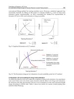
(IAEA, 2008). Figure 2 shows the data acquisition signal path for an OLM system.
Fig. 2. Data Acquisition Signal Path for OLM
Nuclear Power Plant Instrumentation and Control
63
An OLM system is made up of a data acquisition module involving hardware and software
and a data processing module involving software implemented on a fast computer. The data
acquisition module includes signal isolation devices as well as fast sampling capabilities
(e.g., 1000 Hz). If the data is sampled fast, it can be used for both calibration verification by
DC signal analysis using averaging and modeling techniques, and response- time testing by
AC signal analysis using the noise analysis technique (Hashemian, 2009b).
Dynamic analysis
of nuclear plant sensors and equipment uses AC signal analysis to determine how sensors
and equipment react to fast-changing events such as temperature or pressure steps, ramps,
spikes, etc. (Hashemian, 2009b).
OLM originated from reviews of equipment performance data from a variety of industries.
These reviews showed that a majority of process equipment performs well for long periods
of time and that frequent hands-on maintenance is not needed and is sometimes
counterproductive. For example, research performed by Emerson Company’s Rosemount
Division which manufactures process sensors such as pressure, level, and flow transmitters
for a variety of industries has shown that these sensors perform well for periods of ten to
twenty years and need little hands-on maintenance (Hashemian, 2008).
Based on such
research, it is now known that over 70% of maintenance work on pressure transmitters in
industrial processes does not reveal problems, and maintenance intervals can therefore be
extended (AMS, 2010b).
Building on such findings, over the past twenty years, the nuclear power community has
made substantial strides to establish OLM technologies in the industry. Numerous
academic, government, and industry institutions (as well as private companies) have
sponsored R&D efforts in this area. As a result, the feasibility of OLM technologies has
been successfully demonstrated for implementation in the existing nuclear fleet (AMS,
2010b).
Moreover, the NRC has approved the OLM concept for in-situ determination of the
calibration status of pressure, level, and flow transmitters in nuclear power plants. That is,
nuclear power plants can use OLM to establish when a pressure, level, or flow transmitter
must be calibrated.
Although OLM provides substantial benefits to the safety and economy of nuclear power
plants and has been approved by the NRC, OLM use in nuclear power plants is fragmented
and sporadic (Hashemian, 2009b; Electric Power Research Institute [EPRI], 2008; AMS,
2010b).
For example, the Sizewell B plant in the United Kingdom was able to extend the
calibration intervals of 70% of the transmitters that were eligible for calibration extension
using OLM techniques. Similarly, as noted, TXU Comanche Peak nuclear power plant
currently has the largest installation of wireless sensors in the world in its $14 million
wireless network. Most of existing nuclear power plants have the capabilities and
equipment needed for implementing many of the OLM technologies. However, for most
plants, these capabilities are not used to their fullest extent for OLM applications
(Hashemian, 2009b).
One reason is that the implementation of OLM techniques depends on the availability of
data from a large network of sensors deployed on equipment such as motors, fans, pumps,
etc. While many nuclear power plants have an OLM or predictive maintenance program for
equipment outside of their containments, none have OLM programs for equipment inside
the containments due to the sensor wiring costs and penetration space limitations (AMS,
2010b).
Today, a majority of industrial equipment does not benefit from OLM technologies
Nuclear Power – Control, Reliability and Human Factors
64
partly because no sensors exist to provide the necessary data, and installing wired sensors is
often cost prohibitive and impractical.
Wireless sensors will help fill this gap, enabling condition-monitoring technologies
to flourish (Hashemian, 2008).
As a result, wireless sensors promise to experience
explosive growth over the next decade in OLM. Incorporating a wireless infrastructure
will help new plants to provide the necessary means of communicating OLM data to
plant engineers at low cost, and provide a means for the future expansion of OLM
capabilities (Hashemian, 2009b).
Inevitably, research in OLM methods will continue, and
there will be a need to measure and analyze parameters that are not being considered
now.
The application of wireless sensors for equipment condition monitoring in industrial
processes has left open a critical gap in the handling of data from wireless sensors, in
the guidelines that define which parameters must be measured, in the type and number
of sensors to be deployed for measuring these parameters, and in the methods for
ensuring that optimum data is gathered to monitor the health and condition of various
equipment.
Furthermore, over the next few years, the use of wireless sensors will generate an enormous
amount of data from industrial processes. Although much thought has been focused on
developing wireless sensors, little or no effort has been expended on data qualification and
data processing techniques for these sensors. Moreover, little effort has been spent in
determining the type of parameters that should be measured and what the correlation
should be between these parameters and the actual condition of the equipment being
monitored (Hashemian, 2008).
In the next generation of reactors OLM systems should be built into the design so as to
provide automated measurements, condition monitoring, and diagnostics to contribute to
optimized maintenance of the plant (Hashemian, 2009b). Reactor designs for next-
generation plants will typically incorporate an integrated digital infrastructure including
highly integrated control rooms, fault-tolerant control systems, and monitoring systems
with large amounts of available information and data. Most of these digital systems will be
designed to monitor their own performance continuously, self-correct for identified
changes, and function more reliably than previous designs (Hashemian, 2009b).
To develop OLM for future needs, considerations will be needed for increased availability of
process sensor data in the plant computer, higher sampling frequency and resolution data
acquisition capabilities, increased redundancy for critical process sensors, and more flexible
infrastructure to accommodate future data acquisition needs. Utilities will have to adapt to
continuous 24-hour monitoring of instrumentation (AMS, 2010b).
7. Conclusion
Today, OLM technologies and techniques have evolved to the point where in many
cases equipment failures and/or maintenance needs can be adequately predicted days,
weeks, or even months in advance of a system or equipment failure (AMS, 2010b).
In
general, a wireless system provides the lowest overall cost for large-scale OLM
applications (IAEA, 2008).
In the years ahead, future I&C will be fully digital (software
based), distributed, bus connected, amenable to OLM, and qualified to industrial
standards (IAEA, 1999).
Nuclear Power Plant Instrumentation and Control
65
8. References
Analysis and Measurement Services Corp. (February 2010a). “On-Line Monitoring of
Accuracy and Reliability of Instrumentation and Health of Nuclear Power Plants,”
Final Project Report, DOE Grant No. DE-FG02-06ER84626.
Analysis and Measurement Services Corp. (November 2010b). “Implementation of Wireless
Sensors for Equipment Condition Monitoring in Nuclear Power Plants, SBIR Phase
II Final Report, DOE Grant No.: DE-FG02-07ER84684.
Bickel, J. (December 11, 2009). “Digital I&C Is Safe Enough,” Nuclear Engineering
International.
Electric Power Research Institute. (November 2008). “Requirements for On-Line Monitoring
in Nuclear Power Plants,” Final Report, EPRI, Palo Alto.
European Nuclear Agency. (July 2008). “Inspection of Digital I&C Systems – Methods and
Approaches,” Proceedings of a CNRA Workshop, Garching, Germany, 24-26
September 2007, OECD ENA.
Hashemian, H.M. (1999). “Advanced Sensor & New I&C Maintenance Advanced Sensor
and New I&C Maintenance Technologies for Nuclear Power Plants,” Paper
presented at POWID conference, International Society of Automation.
Hashemian, H.M. (2006). Maintenance of Process Instrumentation in Nuclear Power Plants,
Springer Verlag, ISBN 978-3-642-07027-3Berlin, Heidelberg.
Hashemian, H.M. (2008). Predictive Maintenance of Critical Equipment in Industrial
Processes, dissertation for Lamar University.
Hashemian, H.M. (2009a). “State of the Art in Nuclear Power Plant I&C,” International
Journal of Nuclear Energy Science and Technology, Volume 4, No. 4, page 330-354.
Hashemian, H.M. (2009b). On-Line Monitoring Applications in Nuclear Power Plants,
doctoral dissertation, Chalmers University of Technology.
Hashemian, H.M. (Forthcoming). “Sensors for Next-Generation Nuclear Plants: Fiber-Optic
and Wireless,” Nuclear Science and Engineering.
Hirsch, Dr. H. (November 05, 2009). “Statement on the Separation of Safety I&C and
Operational I&C: Expanded Version,” Greenpeace.org.
Hurst, T. (January 2007). “Tow nuclear power I&C out of the ‘digital ditch,’" Power
magazine.
International Atomic Energy Agency. (1999). Modern Instrumentation and Control for
Nuclear Power Plants: A Guidebook, IAEA, Vienna.
International Atomic Energy Agency. (2008). On-Line Monitoring for Improving Performance of
Nuclear Power Plants, Part 1: Instrument Channel Monitoring, NP-T-1.2, and Part 2:
Process and Component Condition Monitoring and Diagnostics, NP-T-1.2, IAEA,
Vienna.
International Atomic Energy Agency. (n.d.). “Instrumentation and Control (I&C) Systems in
Nuclear Power Plants: A Time of Transition,” IAEA, Vienna.
Lipták, Béla G. (2006). “Safety Instrumentation & Justification of Its Cost,” Instrument
Engineers’ Handbook, 4
th
ed., Taylor & Francis, ISBN o-8493-1081-4, Boca Raton,
FL.
Nuclear Power – Control, Reliability and Human Factors
66
Oak Ridge National Laboratory. (May 2007). “Industry Survey of Digital I&C Failures,”
ORNL, Oak Ridge, TN.
U.S. Nuclear Regulatory Commission. (2011). “Digital Instrumentation and Controls,” U.S.
NRC, Washington, DC.
4
Design Considerations for the
Implementation of a Mobile IP Telephony
System in a Nuclear Power Plant
J. García-Hernández
1
, J. C. Velázquez- Hernández
1
,
C. F. García-Hernández
1
and M. A. Vallejo-Alarcón
2
1
Electric Research Institute (IIE)
2
Federal Commission of Electricity (CFE)
Mexico
1. Introduction
IP telephony, also called voice over Internet protocol (VoIP), is rapidly becoming a familiar
term and technology that is implementing in the enterprise, education, government
organizations and industry. Mobile IP telephony is the new generation of communications
networks that makes possible the convergence of voice and data over wireless local area
networks (WLANs). This technology combines data networks with mobile technologies to
support voice and data applications over a common integrated network. A key advantage of
IP telephony is that it allows the transmission of voice signals from conventional telephones
over an IP data network, being either a public network (Internet) or a private network
(Intranet). Figure 1 shows a general IP telephony system. IP telephony is designed to replace
the legacy TDM (time division multiplexing) technologies and networks by an IP-based data
network. Digitized voice will be carried in IP data packets over a LAN and/or WAN
network. A major aspect involved in a voice conversation using mobile IP telephony is the
conversion of analog or digital voice signals from conventional phones to IP packets for
further transmission either to a fixed or mobile phone, over an IP network. One of the most
important recommendations that can be made is to pay close attention to the infrastructure
Fig. 1. General IP telephony system
Internet/Intranet
Gatewa
y
Public Telephone
Network
Gateway
Public Telephone
Network
Nuclear Power – Control, Reliability and Human Factors
68
that the IP telephony network is built on. The design considerations must be solid otherwise;
there will be ongoing quality issues until the network design issues are resolved. Even though
IP telephony have made some vast reliability and quality improvements in recent years,
customers and network designers still struggle with implementing the technology in a multi-
vendor network. There are many reasons for this, such as interoperability issues and
proprietary protocols. In addition, the use of new wireless technologies in nuclear power
plants is growing fast. The WLAN technology based on the IEEE 802.11 standard has a very
promising future for its use in nuclear power plants, due to features like mobility, reliability,
security, scalability and compatibility with other technologies in order to provide new services
such as voice over IP (VoIP) and IP video (Shankar, 2003).
In this work, the design considerations for the implementation of a mobile IP telephony
system in a nuclear power plant based on national and international standards are
presented, as well as, technical requirements that commercially available equipment must
meet. In addition, this work gives an analysis of the most relevant wireless technologies
currently available that can be implemented in nuclear power plants and also identifies
nuclear regulatory guidelines, wireless networks standards, electromagnetic and radio-
frequency interference standards. In the next sections, an analysis of the most relevant
wireless technologies currently available that can be implemented in nuclear power plants is
presented.
2. Wireless LAN standards
The Institute of Electrical and Electronics Engineers (IEEE) has been produced a series of
standards for wireless networks referred as 802.11x, for wireless LAN (Local Area
Networks). The original standard used to implement wireless LANs was 802.11 (IEEE,
1999a). It was first published in 1999 and designed to support a maximum data rate of 2
Mbps in the 2.4 GHz band. This standard uses two modulation techniques: frequency
hopping spread spectrum (FHSS) and direct sequence spread spectrum (DSSS). Figure 2
shows the IEEE 802.11 standard architecture.
Fig. 2. The IEEE 802.11 Standard Architecture
2.1 The IEEE 802.11b standard
Wireless Fidelity (Wi-Fi) networks are intended to be implemented more in enterprises and
in industry. Wi-Fi is commonly used as the abbreviation of 802.11b standard. It supports
PHY
MAC
IEEE 802.2
Logical Link Control (LLC)
IEEE 802.11
Media Access Control (MAC)
Frequency
Hopping
Spread
Spectrum
Direct
Sequence
Spread
Spectrum
Infrared
OSI Layer 2
(Data Link)
OSI
Layer 1
(Physical)
Design Considerations
for the Implementation of a Mobile IP Telephony System in a Nuclear Power Plant
69
bandwidth up to 11 Mbps, comparable to traditional Ethernet. The 802.11b standard also
uses DSSS as modulation technique in the 2.4 GHz band as the original 802.11 standard,
where Wi-Fi devices communicate to each other at data rates up to 11 Mbps (IEEE, 1999b).
In case of any radiofrequency or interference signal cause errors in data transmission, Wi-Fi
devices will automatically reduce their data rate to 5.5 Mbps, to 2Mbps and finally to 1
Mbps (Martínez, 2002). These occasional reductions in the data rate are aimed to keep the
network very stable and highly reliable. Some advantages of Wi-Fi standard are: high data
rates, reliable, wide signal ranges and supports of all 802.11 devices using DSSS.
2.2 Other IEEE 802.11x standards
Along with the 802.11, other standards have been developed (Martínez, 2002): 802.11a,
802.11g, 802.11e and 802.11i. The 802.11a standard (IEEE, 1999c) was published in 1999 and
uses Orthogonal Frequency Division Multiplexing (OFDM) to support bandwidth up to 54
Mbps and signals in the unlicensed frequency spectrum around 5.8 GHz. This higher
frequency compared to 802.11b limits the range of 802.11a networks. The higher frequency
also means 802.11a signals have more difficulty penetrating walls and other obstructions. To
solve this problem and to cover a similar range that 802.11b, a greater number of access
points must be installed. Because 802.11a and 802.11b utilize different frequencies, the two
technologies are incompatible with each other. The 802.11g standard (IEEE, 2003) attempts
to combine the best of both 802.11a and 802.11b standards. It uses OFDM to support
bandwidth up to 54 Mbps, using the 2.4 GHz band for greater range. 802.11g is backwards
compatible with 802.11b, meaning that 802.11g access points will work with 802.11b wireless
network adapters and vice versa. Also, 802.11g produces less multipath losses than 802.11a.
The 802.11e standard (IEEE, 2005) has been developed to support applications with quality
of service (QoS) requirements. It supports a wide range of real-time applications such as
voice, audio, video and data over WLAN. It adopts time scheduling and polling
mechanisms to cope with delay sensitive traffic. The 802.11i standard (IEEE, 2004) has been
developed to improve the security of data provided by Wired Equivalent Privacy (WEP)
protocol in 802.11b. 802.11i incorporates an entirely new privacy algorithm and
authentication mechanism based on the Advanced Encryption Standard (AES).
3. Electromagnetic interference standards
Electromagnetic interference (EMI), radio-frequency interference (RFI), and power surges
have been identified in (NUREG, 2003) as environmental conditions that can affect the
performance of safety-related electrical equipment in a nuclear power plant. A series of
comprehensive commercial EMI/RFI immunity standards have been issued by the
following international organizations:
International Electrotechnical Commission (IEC)
European Committee for Electrotechnical Standardization (CENELEC)
International Special Committee on Radio Interference (CISPR)
These international organizations have produced standards for general application.
National organizations in countries like United States of America, Canada, Australia and
Europe have their own standards that regulate EMI/RFI immunity of electronic equipment.
In the U.S., the Nuclear Regulatory Commission (NRC) has produced the most
comprehensive guide known as Regulatory Guide 1.180 (NRC, 2003) with the aim of
Nuclear Power – Control, Reliability and Human Factors
70
developing the technical basis for regulatory guidance to address electromagnetic
interference, radio-frequency interference, and surge withstand capability in safety-related
instrumentation and control systems in a nuclear power plant.
3.1 Regulatory guide 1.180
This regulatory guide endorses design, installation, and testing practices acceptable to the
NRC staff for addressing the effects of EMI/RFI and power surges on safety-related
instrumentation and control systems in a nuclear power plant environment. This regulatory
guide is based on the standards: IEEE 10-50 (IEEE, 1996), MIL-STD-461E (DoD, 1999) and
IEC 61000 series (IEC, 2002). For instance, the design and installation practices described in
the IEEE 1050 standard are endorsed for limiting EMI/RFI subject to the conditions stated in
the Regulatory Position. Electromagnetic compatibility (EMC) testing practices from
military and commercial standards are endorsed to address electromagnetic emissions,
EMI/RFI susceptibility, and power surge withstand capability. The MIL-STD-461E standard
contains test practices that can be applied to characterize EMI/RFI emissions. In addition,
selected EMI/RFI test methods from MIL-STD-461E and the IEC 61000 series are endorsed
to evaluate conducted and radiated EMI/RFI phenomena for safety-related control and
instrumentation systems. The IEC electromagnetic compatibility (EMC) standards include
IEC 61000-3 (part 3: Limits), IEC 61000-4 (part 4: Testing and measurement techniques), and
IEC 61000-6 (part 6: Generic standards). This regulatory guide also endorses electromagnetic
operating envelopes corresponding to the MIL-STD-461E test methods. These operating
envelopes were tailored from the MIL-STD-461E test limits to represent the characteristic
electromagnetic environment in key locations at nuclear power plants. Comparable
operating envelopes for the IEC 61000 test methods are also endorsed. The Regulatory
Guide 1.180 was updated in the year 2003 to provide additional acceptable methods for
validating the performance of instrumentation and control systems and includes guidance
on testing to address signal line susceptibility and very high frequency (>1GHz)
phenomena.
4. Wireless LAN technologies
The use of wireless technologies in industrial and power utility environments, including
their use in nuclear power plants is growing fast. The wireless technologies that have been
implemented in nuclear power plants include paging systems, digital mobile radio and
cellular systems. Currently, WLAN technology is been installing and evaluating in nuclear
power plants, due to it provides enhanced features compared to traditional wireless
communications technologies such as conventional mobile radio in two key aspects:
Higher operation frequencies
Lower output power
WLAN technology is based on the 802.11 standard and generally operates at higher
frequencies (2.4/5 GHz) and at significantly lower effective power output levels (20 mW-
1W) than UHF/VHF (890/450 MHz) communication systems operating at power output
levels between 4-5 W. This feature of more modem wireless devices, including WLANs,
general1y requires that the end user be closer to a potentially sensitive device before
interference is noted. So, it can be inferred that modem wireless devices are less of a threat
and less like1y to interfere with nuclear power plant equipment than older devices; that is,
Design Considerations
for the Implementation of a Mobile IP Telephony System in a Nuclear Power Plant
71
more modern devices tend to be less intrusive. Those features make that the electromagnetic
interference generated by devices based on WLAN technology does not affect significantly
to safety-related instrumentation and control equipment (EPRI, 2003). In 2002, the Electric
Research Institute (EPRI) published a report in which EPRI developed guidelines for the use
of wireless technologies in nuclear power plants (EPRI, 2002). The purpose of this report
was the evaluation of wireless technologies in nuclear power plants for integrated (voice,
data and video) communication, remote equipment and system monitoring, and to
complement an electronic procedures support system. The guidelines effort focuses on the
development of a rules structure to support the deployment of wireless devices in a nuclear
power plant without compromising continuous, safe, and reliable operation. For these
reasons, spread spectrum appears to be the most adequate technology for the nuclear power
environment.
4.1 Frequency spectrum regulation
The Federal Communications Commission (FCC), organism that manages and regulates the
electromagnetic spectrum in U.S. assigned in 1985 to ISM band the 900 MHz, 2.4 GHz and
5.8 GHz frequency ranges. These regulations are specified in the CFR-47 section 15.2.47
(FCC, 2004). The ISM band is a license-free band and it is used by WLAN technology. In
Mexico, the Consultative Committee for Standardization in Telecommunications (CCNNT)
manages and regulates the electromagnetic spectrum (CCNNT, 2001). Table 1, shows the
frequency ranges and bandwidth reserved for the ISM band for their use the U.S. and
Mexico.
ISM Band Bandwidth
902 – 928 MHz 26 MHz
2.4 – 2.4835 GHz 83.5 MHz
5.725 – 5.850 GHz 125 MHz
Table 1. Reserved frequencies for the ISM band
The FCC set these ISM bands for license-free and low power radio transmission over short
to medium distances (Meel, 1999). The FCC requires that the signal be distributed over a
wide swath of bandwidth using a spread spectrum technology originally developed by the
military for anti-jamming applications. Wireless devices that operate in these license-free
bands can allow immediate, real-time commissioning of a network, avoiding the delays
associated with installing wiring or cables. By spreading data transmissions across the
available frequency band in a prearranged scheme, spread spectrum encoding technology
makes the signal less vulnerable to noise, interference, and snooping. The significant
amount of metal often found in industrial settings can cause signals sent over a single
frequency to bounce and cancel other signals arriving at the same time. Spread spectrum
technology helps overcome this problem and allows multiple users to share a frequency
band with minimal interference from other users.
4.2 Radiated power regulation
The power level radiated by an antenna in a WLAN is specified by the rules stated in the
FCC section 15.247 for operation in the U.S. (FCC, 2004). The FCC also limits the increase in
Nuclear Power – Control, Reliability and Human Factors
72
the output power of the antenna to a maximum of 6 dBi. So, the radiated power is limited to
a maximum of 1W for the 2.4 GHz band. In Mexico it is limited to a maximum of 650 mW
(CCNNT, 2001). In Europe and Japan, the radiated power levels are different to those
allowed for U.S. and Mexico. Table 2, shows the maximum radiated power levels allowed
for different countries (Meel, 1999).
Maximum
Transmit Power
Geographical
Location
Compliance Document
1000 mW U.S.A. FCC 15.247
650 mW Mexico CCNN-T
100 mW Europe ETS 300-328
10 mW/MHz Japan
MPT ordinance for
Regulating Radio
Equipment, article 49-20
Table 2. Maximum transmit power
4.3 Bandwidth regulation
Data throughput is adversely affected by distance and the amount of noise or interference in
the area. If too many wireless devices are operating in the same vicinity, they can interfere
with each other, restricting network capacity. In terms of protection from interference, the
FCC and CCNN-T specify that WLANs operating in the three ISM bands, use spread
spectrum (SS) as the encoding technique to comply with regulation requirements (Meel,
1999; DoE, 2002; Pearce, 2001). Spread spectrum technology is based on two interference
avoidance techniques: frequency hopping spread spectrum (FHSS) and direct sequence
spread spectrum (DSSS). Both modulation schemes have been defined in (IEEE, 1999b) to
operate in the 2.4 GHz band, using a bandwidth of 83 MHz (from 2.400 GHz to 2.4835 GHz).
Also, the CCNNT specifies that the bandwidth of the transmitted signal depending on the
modulation scheme (FHSSS or DSSS) employed (CCNNT, 2001), as shown in table 3. FHSS
technique permits the fast movement or “hopping” to any channel within the total allocated
spectrum. Here, the carrier frequency hops from channel to channel in some pre-arranged
sequence. The major drawback to this technique is a limited data rate.
SS Modulation
scheme
Bandwidth
Frequency Hopping
(FHSS)
1 MHz (maximum)
Direct Sequence (DSSS)
500 KHz
(minimum)
Table 3. Bandwidth of transmitted signal
By contrast, DSSS technique provides much higher data rates. Here, the carrier frequency
does not jump from frequency to frequency, but instead spreads the information across a
much wider bandwidth. Also, DSSS can provide many users to be on the same channel at
the same time and be distinguished from each other by a digital code. DSSS uses the phase
shift keying modulation technique known as differential BPSK (DBPSK) and differential
BPSK (DQPSK). FHSS uses the frequency shift keying modulation technique known as 2
Design Considerations
for the Implementation of a Mobile IP Telephony System in a Nuclear Power Plant
73
and 4 level Gaussian FSK (2GFSK and 4GFSK). The data rate for both FHSS and DSSS
schemes is defined in (IEEE, 1999a; IEEE, 1999b). Table 4, shows the maximum data rates for
the physical layer supported by the most commonly used 802.11 standards. The most
common problem when applying an unlicensed wireless system in an industrial
environment is radio frequency interference or better known as “radio noise”. Both FHSS
and DSSS handle noise differently and can have certain advantages depending on the type
of interference experienced.
Standard
Frequency
band (GHz)
Modulation
scheme
Maximum bit
rate
IEEE 802.11 2.4 - 2.4835 FHSS 2 Mbps
IEEE 802.11 2.4 - 2.4835 DSSS 2 Mbps
IEEE 802.11b 2.4 - 2.4835 DSSS 11 Mbps
Table 4. Maximum data rates for WLANs
5. Use of wireless LANs in the nuclear environment
The WLAN technology based on the IEEE 802.11 standard has a very promising future for
its use in nuclear power plants due to features like mobility, reliability, security,
scalability and compatibility with other communication networks technologies in order to
provide new services such as voice over IP (VoIP) and IP video (Shankar, 2003). A key
issue of these technologies is that no wires are needed to implement new services.
Currently, WLAN technology is been installing and evaluating in nuclear power plants,
due to it provides enhanced features compared to traditional wireless communications
technologies such as conventional mobile radio in two key aspects: higher operation
frequencies and lower output power which translates in very high data rates and very low
electromagnetic interference. However, wireless technology may exhibit greater
vulnerability to the nuclear power plant EMI/RFI environment than existing
instrumentation and control systems. The typical environment in a nuclear power plant
includes many sources of electromagnetic interference (EMI), radio-frequency interference
(RFI), and power surges, such as hand-held two-way radios, arc welders, switching of
large inductive loads, high fault currents, and high-energy fast transients associated with
switching at the generator or transmission voltage levels. Hence, operational and
functional issues related to safety in the nuclear power plant environment are required to
address the possibility of troubles and malfunctions in instrumentation and control
systems caused by EMI/RFI and power surges.
The wireless communications technologies that can be implemented in nuclear power plants
include paging systems, mobile radio, cellular systems and wireless local area networks
(WLANs). Recently, there has been a significant increase in the use of wireless technology in
nuclear power plants. For example, wireless technology has been installed and evaluated in
nuclear power plants by utility companies throughout the U.S., Canada, Mexico, Europe,
and worldwide (Bahavnani, 2001; Telrad Connegy, 2001; Wireless Magazine, 1995). Wireless
technology has many applications in the industry, including cellular phone systems, paging
systems, two-way radio communication systems, dose management in nuclear power
plants, remote monitoring and tracking systems, and operator logs (EPRI, 2004a). In
addition, EPRI has reported the following case studies: Exelon´s Peach Bottom Nuclear