Nuclear Power Control, Reliability and Human Factors Part 2 pot
Bạn đang xem bản rút gọn của tài liệu. Xem và tải ngay bản đầy đủ của tài liệu tại đây (738.89 KB, 30 trang )
Sensor Devices with High Metrological Reliability
19
current sensor coil parameters and their reference values determined at the original
calibration.
(a) (b)
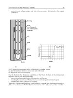
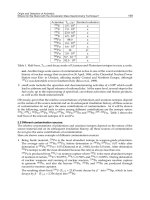
Fig. 3. System for measuring control rod position in a nuclear reactor
(a) simplified scheme of sensor device and rack with shunt
(b) diagram of drive rack: a step up
Fig. 3b illustrates the diagnostic capabilities of the IS on the basis of the displacement
diagrams analysis. The diagram enables:
determining the actuation time of the transfere unit latches,
checking the correctness of the response to an electromagnet current cyclogram,
checking the control rod and rack coupling.
The ability to obtain such diagrams is determined by both the high displacement sensitivity
of the sensor device and the fact that the time interval between two consecutive control rod
Nuclear Power
– Control, Reliability and Human Factors
20
position measurements is very short. In case of the drive fault, the shape of the diagram is
changing. This makes it possible to find out the origin of the fault or to reveal the incipient
malfunction (even before appearance of a significant failure). Information about all the CR
moves, control commands, operation modes, occurred malfunctions or failures as well as
operator’s actions are logged in a “black box” recorder. At the same time, the IS estimates
the drive operating time by accumulating the parameters like the number of drops, steps
made, input control signals, etc.
The real time CR position is displayed on a front panel. Each IS can be connected to a local
network. With the help of the network, the ISs can perform cross-system diagnostics. This
improves the IS fault-tolerance. For instance, the local network gives an opportunity to
inform operators about the wrong positions of CR, including the case of CR position
mismatch in the control group as well as of any CR slipping down from the end switch.
Based on diagnostic information obtained during system operation, an individual
“registration certificate” is automatically issued for each drive. This certificate contains an
assessment of the drive condition as well as recommendations for operators how to carry
out a preventive maintenance.
Three ISs operated for many years at the power unit of the Kalinin NPP in Russia and
were highly appraised by specialists. For that time interval, the first modification of the
processing unit was replaced by a new one. The software parts related to diagnostics were
improved. During the operation period, sensor signals varied insignificantly, and a
tendency to stabilize the parameters was noticed. During the last years, the average
change of resistance of sensor coils was less than 0.2% per year. Extrapolation of the
resistance-time function for 60 years shows that the predicted sensor resistance variation
is less than 3.5%. With the ability to automatically correct each individual sensor
parameter variations within about 25%, the sensor device lifetime is much longer than it is
required.
The use of the ISs improved the service effectiveness. It was more convenient for the stuff
to work with textual recommendations from IS in case of malfunction. When the
emergency shutdown of the power unit happened, the IS diagnostic capabilities helped
to localize the failure even outside the ISs. Monitoring abilities are sufficient to extend the
equipment lifetime by switching from pre-assigned lifetime to prediction of the state
during future fuel cycle. As a result, the power plant can utilize equipment capability
to the very end. In particular, the assessment based on the IS “black box” data at the
Kalinin NPP gave the basis to increase significantly a projected lifetime of transfer unit
and rack.
The additional study has shown that the electromagnet temperature can be decreased if a
special inexpensive auxiliary component is added to the electromagnet.
Altogether, the developed technical solutions enable the lifetime of the equipment to
become equal to the lifetime of the reactor vessel. Some additional information with respect
to the IS considered has been given in the paper presented at the IAEA meeting
(Sapoznikova et al., 2005b). The main ideas used in the IS can be applied to the control and
protection systems of other reactor types.
9. Registration of self-check results. Status of measurement results
An estimate of the measurement error obtained in calibrating a given measuring
instrument, cannot be transferred to the measurement results obtained with the help of
Sensor Devices with High Metrological Reliability
21
this instrument significantly later in the process of operation, since the instrument error
component changes with time. The metrological self-check results are characterized by
some error too.
It is not necessarily the case for the error to be determined quantitatively according to the
metrological self-check data. For a significant part of applications, the qualitative estimate of
the measurement reliability, by giving a certain “measurement value status” to the result of
measurement, is expedient. For the first time, this concept was introduced in (Henry &
Clarke, 1993). The following gradations of the status are recommended there: secure, clear,
blurred, dazzled, blind. In the joint paper of Oxford and St.Petersburg scientists
(Sapozhnikova et al., 2005a) a comprehensive reasoning of the necessity to introduce the
measurement value status is given and some details of definitions and recommendations are
proposed. It is noted that the number of status gradations should depend on the number of
human operator’s actions required in response to information about the measurement value
status. The number of responses is usually no more than 5.
The status called “confirmed” indicates that a measurement result has been confirmed by
additional information about the metrological serviceability of an intelligent sensor device
or intelligent multichannel measuring system, and a risk to use an unreliable measurement
result is negligible. This status is desirable in making very important decisions on
equipment control. The status “confirmed” can be given to a measurement result obtained
from a sensor device or measuring system when information at their output shows that they
are in a “healthy“ state.
The status called “normal” indicates that a risk to use an unreliable measurement result is
small, which allows, for example, a decision on equipment control to be made in ordinary
situations. This status can be given to the measurement result obtained within the
calibration interval from a sensor device or multichannel measuring system, the
metrological serviceability of which is not automatically checked in the process of
operation.
The status called “orienting” indicates that a risk to use an unreliable measurement result
increases due to a defect in a sensor device or multichannel measuring system, but the result
of measurement can be applied for an orienting estimate of the equipment condition and
that of the technological process under control. The “orienting” status is sufficient for
making a decision in the case, for example, when parameters of the technological process
are far from the borders allowed. Giving the status “orienting” to the measurement result,
indicates the need to perform the maintenance of a sensor device or measuring system as
well as to set the terms of this maintenance.
The status called “extrapolated” indicates that as a result of measurement they use the
result obtained by extrapolating the data from the preceding time interval, since received
information is unreliable during the known time interval that is rather short. The status
“extrapolated” gives grounds, for example, to delay making a very important decision on
equipment control before receiving reliable information or to make a certain cautious
decision, orienting by a hypothesis that within this known time interval the condition of
the equipment and flow of the controlled technological process do not change
significantly.
The status called “unreliable” indicates that a risk to use an unreliable measurement result
is great. The decision should be made to perform the maintenance of a sensor device or
measuring system.
Nuclear Power
– Control, Reliability and Human Factors
22
Status gradations can be joined into three groups which demonstrate the level of risk:
status “confirmed” or “normal”;
status “orienting” or “ extrapolated“;
status “unreliable”.
Furthermore, the results of the metrological self-check can include:
an estimate of the error (taking into account a correction when it was made) or critical
error component;
time when the corresponding estimate was obtained;
an estimate of a residual metrological life;
history of metrological self-check data.
10. Conclusion
The technological expansion has led to the situation, when the conventional methods of
metrological assurance have ceased to satisfy the high requirements of nuclear power
engineering, astronautics and a number of other fields of science and industry for the
metrological reliability of measuring instruments. The measurement information validity
becomes insufficient.
The similarity of the evolution of measuring instruments and biological sensor systems has
created a basis for forecasting a significant complication of sensor devices and growth of the
need for intelligent sensor devices and intelligent multichannel measuring systems with the
metrological self-check.
This chapter deals with the general approach to the development of intelligent sensor
devices. This approach is illustrated by a number of examples of the measuring instruments
including those developed under leadership of the authors, namely, the temperature and
pressure sensor devices as well as the intelligent system intended for measuring the position
of control rod in a nuclear reactor.
It is shown that in the process of operation, the sensor devices with the metrological self-
check can provide:
practically continuous check of the measurement information reliability;
forecast of the metrological state of a sensor device on the basis of the self-check results
obtained in the previous period of time;
automatic correction of the sensor device parameters (in a number of cases).
A growth of the need for intelligent and data-redundant sensor devices is confirmed not
only by the examples showing that in various countries such devices and corresponding
standards and guides (BSI, 2005; GOST R, 1996, 2009; MI 2021, 1989; VDI/VDE, 2005) were
developed.
An increasing number of publications devoted to the topic considered, as well as
organization of special sessions at international conferences and preparation of new
standards (in particular, e.g., the Russian draft standard “State system for ensuring the
uniformity of measurements. Intelligent sensors and intelligent measuring systems.
Methods of metrological self-checking”), indicate the growth of this need too.
Under the conditions of economics globalization , the enhancement of requirements for the
operating safety of various equipment, especially, nuclear reactors, obliges scientists and
engineers to develop unified international requirements for standardizing the characteristics
Sensor Devices with High Metrological Reliability
23
of self-checked sensor devices and multichannel measuring systems as well as
corresponding terms and definitions with respect to these instruments.
To our point of view, the development of intelligent measuring instruments is a natural
stage of measurement technique evolution.
11. References
Andreeva, L.E. (1981). Elastic Elements of Measuring Instruments. Мoscow: Mashinostroenie.
(in Russian).
Baksheeva, Yu.; Sapozhnikova, K. & Taymanov, R. (2010). Metrological Self-Сheck of
Pressure Sensors, The Seventh International Conference on Condition Monitoring and
Machinery Failure Prevention Technologies, Stratford-upon-Avon, England.
Barberree, D. (2003). Dynamically Self-validating Contact Temperature Sensors, Proceedings
of the Conference “Temperature: Its Measurement and Control in Science and Industry“,
No. 7, AIP Conference Proceedings, Melville, New York, pp. 1097-1102.
Bechtereva, N.P.; Shemyakina, N.V.; Starchenko, M.G.; Danko, S.G. & Medvedev, S.V.
(2005). Error Detection Mechanisms of the Brain: Background and Prospects, Int. J.
Psychophysiol, No. 58, pp. 227-234.
Bera, S.C.; Mandal, N.; Sarkar R. & Maity, S. (2009). Design of a PC Based Pressure Indicator
Using Inductive Pick-up Type Transducer and Bourdon Tube Sensor, Sensors &
Transducers Journal, Vol. 107, No. 8, pp. 42-51, ISSN 1726-5749.
Bernhard, F.; Boguhn, D.; Augustin, S.; Mammen, H. & Donin, A. (2003). Application of Self-
calibrating Thermocouples with Miniature Fixed-point Cells in a Temperature
Range from 500
o
C to 650
o
C in Steam Generators, Proceedings of the XVII IMEKO
World Congress, Dubrovnik, Croatia, pp. 1604-1608.
Berry, R. J. (1982). Oxidation, Stability and Insulation Characteristics of Rosemount Standard
Platinum Resistance Thermometers, Temperature, Its Measurement and Control in
Science and Industry, AIP, New York, Vol.5, pp. 753-761.
Bogue, R. (2009). Inspired by Nature: Developments in Biomimetic Sensors, Sensor Review,
Vol. 29, No.2, pp. 107-111, ISSN 0260-2288.
BSI (2005). Specification for Data Quality Metrics of Industrial Measurement and Control
Systems, BS7986:2005 / British Standards Institute, 389 Chiswick High Rd, London
W4 4AL.
Crovini, L.; Actis, A.; Coggiola, G. & Mangano, A. (1992). Precision Calibration of
Industrial Platinum Resistance Thermometers, Temperature: Its Measurement and
Control in Science and Industry, Vol. 6, edited by J. F. Schooley, New York: AIP,
pp. 1077-1082.
Druzhinin, I.I. & Kochugurov, V.V. (1988) Check-up of Metrological Characteristuics of the
Embedded Eddy-current Transducers, Measurement Techniques, Vol.31, No 11,
pp. 1075-1091, 37-38, ISSN 0543-1972, ISSN 1573-8906.
Feng, Z.; Wang, Q. & Shida, K. (2007). A Review of Self-validating Sensor Technology,
Sensor Review, Vol. 27, No.1, pp. 48-56, ISSN 0260-2288.
Feng, Z.; Wang, Q. & Shida, K. (2009). Design and Implementation of a Self-Validating
Pressure Sensor, IEEE Sensors Journal, Vol. 5, No.3, pp. 207-218, ISSN 1530-
437X.
Nuclear Power
– Control, Reliability and Human Factors
24
Fridman, A.E. (1991). Theory of Metrological Reliability. Measurement Techniques, Vol. 34,
No.11 1075-1091, ISSN 0543-1972, ISSN 1573-8906.
GOST R 8.673-2009. (2009). State System for Ensuring the Uniformity of Measurements.
Intelligent Sensors and Intelligent Measuring Systems. Basic Terms and Definitions.
GOST R 8.565-96. (1996). State System for Ensuring the Uniformity of Measurements.
Metrological ensuring of atomic power stations exploitation. General principles.
Hans, V. & Ricken O. (2007). Self-monitoring and Self-calibrating Gas Flow Meter,
Proceedings of the 8th International Symposium on Measurement Technology and
Intelligent Instruments, Sept 24-27, 2007, pp. 285-288.
Hashemian, H. M. & Petersen, K. M. (1992). Achievable Accuracy and Stability of Industrial
RTDs, Temperature: Its Measurement and Control in Science and Industry, Vol. 6, New
York: AIP, pp. 427-432, ISBN 1-55617-897-2, ISBN 1-55617-932-42.
Hashemian, H.M. (2005). Sensor Performance and Reliability, ISA, USA, ISBN-10 3-540-33703-
2, ISBN-13 978-3-540-33703-4.
Hashemian, H.M. (2006). Maintenance of Process Instrumentation in Nuclear Power Plants.
Berlin, Heidelberg, New-York: Springer.
Henry, M. P. & Clarke, D. W. (1993). The Self-validating Sensor: Rationale, Definitions and
Examples. Control Engineering Practice, Vol.1., No. 4, pp. 585–610.
Henry, M.P.; Clarke, D.W.; Archer, N.; Bowles, J.; Leahy, M.J.; Liu, R. P. et al. (2000). A Self-
validating Digital Coriolis Mass-flow Meter: an Overview, Control Eng. Pract., Vol.
5, No.8 , pp. 487-506.
ISO/IEC 17025 (1999). General Requirements for the Competence of Testing and Calibration
Laboratories.
Karzhavin, V.A. ; Karzhavin, A.V. & Belevtsev, A.V. (2007). About the Possibility to Apply
Cable Nichrosil-nisil Thermoicouples as the Reference Ones, in: Proc. of the 3rd All-
Russian Conference “Temperature-2007”, Obninsk, CD-ROM.
Lem, S. (1980). Summa Technologiae, Verlag Volk und Welt, Berlin.
Li, X.; Zhao, M. & Chen, D. (2010). A Study on the Stability of Standard Platinum Resistance
Thermometer in the Temperature Range from 0 °C through 720 °C.
Lukashev, A.P. ; Karlov, P.A. & Belyakov, A.E. (1984). SU1117472 (A1), Pressure Pickup,
Priority Date: 1983-10-19, Pub. 1984-10-07
Mangum, B. W. (1984). Stability of small industrial PRTs, Journal of Research of the NBS 89,
pp. 305-316.
McFarland, D. (1999). Animal Behaviour. Psycology, Ethology, and Evolution, Prentice Hall.
MI Recommendation 2021-89. (1989). State System for Ensuring the Uniformity of
Measurements. Metrological Assurance of Flexible Manufacturing Systems.
Fundamentals, Committee on Standardization and Metrology.
OIML D 10 (2007). Guidelines for the Determination of Recalibration Intervals of Measuring
Equipment Used in Testing Laboratories.
Reed, R.P. (2003). Possibilities and Limitations of Self-validation of Thermoelectric
Thermometry, AIP Conference Proceedings, Temperature: Its Measurement and
Control in Science and Industry, Vol.7, p. 507, 2D. C. Ripple et al. eds., Melville, New
York.
Sensor Devices with High Metrological Reliability
25
Red'ko, V.G. (2007). Evolution. Neural Networks. Intelligence. Models and Concepts of the
Evolutionary Cybernetics, KomKniga, Moscow.
Sapozhnikova, K.V. Metrological Diagnostic Check, Metrological Service in the USSR, No.2,
pp. 18-24, 1991.
Sapozhnikova, K.V.; Taimanov, R.Ye. & Kochugurov, V.V. (1988). Metrological Checking as
a Component of Diagnostics of Flexible Production Systems and Robotics
Complexes, Testing, Checking and Diagnostics of Flexible Production Systems (from the
materials of the seminar hold at the Blagonravov IMASH of the Academy of Science in
1985). – M.: Nauka, pp. 269-273.
Sapozhnikova, K.; Henry, M. & Taymanov, R. (2005a). The Need for Standards in Self-
diagnosing and Self-validating Instrumentation, Joint International IMEKO
TC1+TC7 Symposium, September 21- 24, 2005, Ilmenau, Germany (CD-ROM).
Sapozhnikova, K.; Taymanov, R. & Druzhinin, I. (2005b). About the Effective Approach to
the Modernization of the NPP Control and Emergency Shutdown System, IAEA
Technical Meeting on “Impact of the Modern Technology on Instrumentation and
Control in Nuclear Power Plants” (621-12-TM-26932) 13-16 Sept. 2005, Chatou,
France (CD-ROM).
Stroble, J.K.; Stone, R.B. & Watkins, S.E. (2009). An Overview of Biomimetic Sensor
Technology, Sensor Review, Vol. 29, No.2 , pp. 112-119, ISSN 0260-2288.
Tarbeyev, Yu.; Kuzin, A.; Taymanov, R. & Lukashev, A. (2007) New Stage in the
Metrological Provision for Sensors, Measurement Techniques, Vol. 50, No.3 , pp. 344-
349.
Taymanov, R.; Sapozhnikova, K. & Druzhinin, I. (2007). Measuring Control Rod Position,
Nuclear Plant Journal, 2007, No.2, pp. 45-47, ISSN 0892-2055.
Taymanov, R. & Sapozhnikova, K. (2009). Problems of Terminology in the Field of
Measuring Instruments with Elements of Artificial Intelligence, Sensors &
Transducers journal, Vol.102, 3, pp. 51-61, ISSN 1726-5749.
Taymanov, R. & Sapozhnikova, K. (2010a). Metrological Self-Сheck as an Efficient Tool of
Condition Monitoring, The Seventh International Conference on Condition Monitoring
and Machinery Failure Prevention Technologies, Stratford-upon-Avon, England.
Taymanov, R. & Sapozhnikova, K. (2010b). Metrological Self-Check and Evolution of
Metrology, Measurement, Vol.43, No.7, pp. 869-877, ISSN 0263-2241.
Taymanov, R.; Sapozhnikova, K. & Druzhinin, I. (2011). Sensor Devices with Metrological
Self-Check, Sensors & Transducers journal, Vol.10 (special issue), No.2, (February
2011), pp. 30-44, ISSN 1726-5749.
Turchin, V.F. (1977). The Phenomenon of Science. A Cybernetic Approach to Human Evolution,
Columbia University Press, New York.
VIM. International Vocabulary of Metrology — Basic and General Concepts and Associated Terms,
JCGM, 2008.
VDI/VDE Guideline 2650 (2005). Requirements for Self-monitoring and Diagnostics in Field
Instrumentation.
Werthschutzky, R. & Muller, R. (2007). Sensor Self-Monitoring and Fault-Tolerance,
Technisches Messen, Vol. 74, No.4, pp. 176-184.
Nuclear Power
– Control, Reliability and Human Factors
26
Werthschützky, R. & Werner, R. (2009). Sensor Self-Monitoring and Fault-Tolerance,
Proceedings of the ISMTII’2009, 29 June – 2 July, 2009, St.Petersburg, Russia, pp.4-
061- 4-065.
Wiener, N. (1948). Cybernetics: Or the Control and Communication in the Animal and the
Machine, MA, MIT Press, Cambridge.
2
Multi-Version FPGA-Based Nuclear Power Plant
I&C Systems: Evolution of Safety Ensuring
Vyacheslav Kharchenko
1
, Olexandr Siora
2
and Volodymyr Sklyar
2
1
National Aerospase University KhAI,
Centre for Safety Infrastructure-Oriented Research and Analysis,
2
Research and Production Corporation RADIY,
Ukraine
1. Introduction
1.1 Problem of decreasing common cause failure probability for nuclear power plant
instrumentation and control systems
To guarantee required level of dependability, safety and security of computer-based systems
for critical (safety-critical, mission-critical and business-critical) applications it is used
diversity approach. This approach implies development, choice and implementation of a
few diverse design options of redundant channels for created system. Probability of
common cause failure (CCF) of safety-critical systems may be essentially decreased due to
selection and deployment of different diversity types on the assumption of maximal
independence of redundant channels realizing software-hardware versions.
This circumstance calls forth that a lot of international and national standards and guides
contain the requirements to use diversity in safety-critical systems, first of all, in nuclear
power plant (NPP) instrumentation and control systems (I&Cs) (reactor trip systems),
aerospace on-board equipment (automatic/robot pilot, flight control systems), railway
automatics (signalling and blocking systems), service oriented architecture (SOA)-based
web-systems (e-science) etc. (Pullum, 2001; Wood et al., 2009; Gorbenko et al., 2009;
Kharchenko et al., 2010; Sommerville, 2011).
Application of the modern information and electronic technologies and component-based
approaches to development in critical areas, on the one hand, improve reliability,
availability, maintainability and safety characteristics of digital I&Cs. On the other hand,
these technologies cause additional risks or so-called safety deficits. Microprocessor
(software)-based systems are typical example in that sense. Advantages of this technology
are well-known, however a program realization may increase CCF probability of complex
software-based I&Cs. Software faults and design faults as a whole are the most probable
reason of CCFs. These faults are replicated in redundant channels and cause a fatal failure of
computer-based systems. It allows to conclude that, “fault-tolerant” system with identical
channels may be “non-tolerant” or “not enough tolerant” to design faults. For example,
software design faults caused more than 80% failures of computer-based rocket-space
systems which were fatal in 1990 years (Kharchenko et al., 2003) and caused 13%
emergencies of space systems and 22% emergencies of carrier rockets (Tarasyuk et al., 2011).
The CCF risks may be essential for diversity-oriented or so-called multi-version systems
(MVSs) (Kharchenko, 1999) as well if choice of version redundancy type and development
Nuclear Power – Control, Reliability and Human Factors
28
of channel versions are fulfilled without thorough analysis of their independence and
assessment of real diversity degree assessed by special metrics, for example, β-factor
(Bukowsky&Goble, 1994).
1.2 Complex electronic components and FPGA technology for NPP I&Cs development
An analysis of development and introduction trends of computer technologies to NPP I&Cs
has specified a number of important aspects affecting their safety, peculiarities of
development, update and licensing. Such trends include, among others (Yastrebenetsky,
2004): introduction of novel complex electronic components (CECs); expanded
nomenclature of software applied and increased effect of its quality to I&Cs safety;
realization of novel principles and technologies in I&Cs development; advent of a large
number of novel standards regulating the processes of I&Cs development and safety
assessment. During recent decades the application of microprocessor techniques in NPP
I&Cs design has substantially expanded. Microprocessors are used both in system computer
core and in realization of intellectual peripherals – various sensors, drives and other devices
with built-in programmable controllers.
Another contemporary trend is dynamically growing application of programmable logic
technologies, particularly, Field Programmable Gate Arrays (FPGA) in NPP I&Cs, onboard
aerospace systems and other critical areas. FPGA as a kind of CECs is a convenient mean not
only in realization of auxiliary functions of transformation and logical processing of
information, but also in execution of basic monitoring and control functions inherent in NPP
I&Cs. This approach in some cases is more reasonable than application of software-
controlled microprocessors (Kharchenko&Sklyar, 2008). In assessment of FPGA-based I&Cs
it should be taken into consideration that application of this technologies somewhat levels
the difference between hardware and software, whereas obtained solutions are an example
of a peculiar realization of so called heterosystems – systems with “fuzzy” software-
hardware architecture and mixed execution of functions. This circumstance and other
features of FPGA technology increase a number of diversity types and enlarge a set of
possible diversity-oriented decisions for NPP I&Cs.
1.3 Work related analysis
Known works, related to the current problem and taking into account features of NPP I&C
systems, are divided into three groups: (1) classification and analysis of version redundancy
types and diversity-oriented decisions; (2) methods and techniques of diversity level
assessment and evaluation of multi-version systems safety in context of CCFs; (3) multi-
version technologies of safety critical systems development.
1. A set of diversity classification schemes (general, software and FPGA-based) was
analyzed in (Kharchenko et al., 2009). First one is based on NUREG technical reports and
guides, samples two-level hierarchy and includes seven main groups of version
redundancy (Wood et al., 2009): signal diversity (different sensed reactor or process
parameters, different physical effects, different set of sensors); equipment manufacture
diversity (different manufacturers, different versions of design, different CEC versions,
etc); functional diversity (different underlying mechanisms, logics, actuation means, etc);
logic processing equipment or architecture diversity (different processing architectures,
different component integration architectures, different communication architectures, etc);
logic or software diversity (different algorithms, operating system, computer languages,
Multi-Version FPGA-Based Nuclear Power Plant I&C Systems: Evolution of Safety Ensuring
29
etc); design diversity (different technologies, approaches, etc); human or life cycle
diversity (different design organizations/companies, management teams, designers,
programmers, testers and other personnel). Software diversity types are classified in
according with following attributes (Pullum, 2001; Volkoviy et al., 2008): life cycle models
and processes of development (for example, V-model for main version and waterfall
model with minimum set of processes for duplicate version); resources and means
(different human resources, languages and notations, tools); project decisions (different
architectures and platforms, protocols, data formats, etc). Next one FPGA-based
classification includes the following types of diversity (Kharchenko&Sklyar, 2008; Siora et
al., 2009): diversity of electronic elements (different electronic elements manufactures,
technologies of production, electronic elements families, etc); diversity of CASE-tools
(different developers, kinds and configurations of CASE-tools); diversity of projects
development languages (different graphical scheme languages, hardware description
languages and IP-cores); diversity of specifications (specification languages) and others.
2. There are following methods of diversity level assessment and evaluation of MVS
dependability and safety (Kharchenko et al, 2009). Theoretical-set and metric-oriented
methods are based on: Eiler’s diagram for sets of version design, physical and
interaction faults (including vulnerabilities for assessment intrusion-tolerance); matrix
of diversity metrics for sets of different faults (individual, group and absolute faults of
versions); calculation of diversity metrics by use of Eiler’s diagrams or other data about
results of testing and faults of different versions. Probabilistic methods use reliability
block-diagrams (RBDs), their modifications (survivability and safety block-diagrams),
Markovian chains, Bayesian method, etc. Statistical methods include the following
procedures: receiving and normalization of version fault trends using testing data;
choice of software reliability growth model (SRGM) taking into account features of
version development and verification processes and fitting SRGM parameters; metrics
diversity assessment; calculation of reliability and safety indicators. Fault injection-
based assessment consists of: receiving project-oriented fault profiles; performing of
faults injection procedure; proceeding of data and metrics diversity calculation;
calculation of reliability and safety indicators. Expert-oriented methods use two groups
of metrics: diversity metrics for direct assessment of versions and MVS reliability and
safety (direct diversity metrics); indirect diversity metrics (product complexity metrics
and process metrics); values of these metrics may be used to assess direct diversity
metrics. Expert methods are added other techniques founded on interval mathematics-
based assessment of diversity metrics and MVS indicators, soft computing-based
assessment (fussy logic, genetic algorithms), risk-oriented approach and so on.
3. Multi-version technologies (MVTs) of diversity types selection and application,
development of MVSs as a whole are based on (Siora et al., 2009; Wood et al., 2009) use of
diversity types and strategies table, a model of multi-version life cycle (MVLC), a special
graph of diversity types and their modifications, and procedures of diversity type and
volume choice according with different criteria. The set of diversity strategies developed
in the (Wood et al., 2009) consists of three families of strategies: different technologies—
Strategy A (digital vs analog), different approaches within the same technology—Strategy
B (microprocessor vs FPGA) and different architectures within the same technology—
Strategy C (IP-based vs VHDL). Each of the strategy families is characterized by
combinations of diversity criteria that may provide adequate mitigation of potential CCF
vulnerabilities according with metrics determined by expert way.
Nuclear Power – Control, Reliability and Human Factors
30
There are a lot of examples of multi-version systems and multi-version technologies
application in different safety critical areas. Generalized results of MVS application analysis
are presented by matrix “types of diversity – areas of multi-version I&Cs application” in
Table 1 (Wood et al., 2009; Kharchenko et al., 2010).
Diversity types
Multi-version I&C systems application
Space Aviation
Railways
Chemic.
іndustry
Defense
Power
Plants
NPPs
e-Commers
Shuttle ISS
MC
JVC
FAA
FCS
Air-
bus
A320
Boeng
777
SCB CCPS MICS
Electr.
Grid
RTS ESFAS WSOA
Design
Equip-
ment
Func-
tio
n
Human
Signal
Soft-
ware
Others
Table 1. Matrix “types of diversity – areas of multi-version I&Cs application”
Types of diversity (diversity redundancy) are classified according to NUREG 6303 and
painted by different colors. Last row of the matrix corresponds to other types of diversity.
MVSs are used in space systems (Shuttle, ISS), aviation equipment (MC JVC, FAA FCS,
Airbus and Boeing on-board systems), railway automatics (signaling, centralization and
blocking systems SCB), chemical industry (CCPS), defense systems, power plants (electricity
grid), NPPs (RTS and ESFAS), e-commerce and e-science (web-systems with diverse target
web-services).
1.4 Goal and structure of the chapter
In spite of the intensive researches in area of multi-version systems and long-term
experience of their application there are some problems of diversity approach
implementation in context of FPGA technology application in NPP I&Cs, videlicet:
specifying of concepts used; selection of diversity types and required volume of version
redundancy; joint use of different diversity types taking into consideration state-of-the-art
technologies; assessment of real diversity degree and effectiveness of MVSs, etc. Goal of the
chapter is analysis of concepts in multi-version computing and diversity-scalable decisions
for FPGA-based NPP I&Cs. Structure of the chapter is following. The section 2 elaborates
the FPGA peculiarities in context of safety critical applications and evolution aspect of
Multi-Version FPGA-Based Nuclear Power Plant I&C Systems: Evolution of Safety Ensuring
31
FPGA-technology and diversity approach conformably to NPP I&Cs. The standards
containing requirements to application of diversity approach in NPP I&Cs and key
challenges in this area are analyzed in the section 3. The taxonomy of multi-version
computing and models of MVSs and MVTs are represented in the section 4. General
approach to assessment of diversity and MVS safety is described in the section 5. Features of
FPGA-based platform RADIY
TM
and results of implementation of multi-version I&Cs in
NPPs are analyzed in the section 6. Finally, the section 7 concludes the chapter and presents
directions of future researches.
2. An evolution of FPGA technology and diversity application in NPP I&Cs
2.1 FPGA peculiarities in context of dependability and safety
FPGA architecture topologically originates from channeled Gates Arrays (GA) (Altera,
2001). In FPGA internal area a set of configurable logic units is disposed in a regular order
with routing channels there between and I/O units at the periphery. Transistor couples,
logic gates NAND, NOR (Simple Logic Cell), multiplexer-based logic modules, logic
modules based on programmable Look-Up Tables (LUT) are used as configurable logic
blocks. All those have segmented architecture of internal connections.
System-On-Chip architecture appeared due to two factors: high level of integration
permitting to arrange a very complicated circuit on a single crystal, and introduction of
specialized hardcores into FPGA. Additional hardcores may be: additional Random Access
Memory (RAM) units; JTAG interface for testing and configurating; Phase-Locked Loop
(PLL) – frequency control system to correct timing relations of clock pulses as well as for
generation of additional frequencies; processor cores enabling creation of devices with a
control processor and a peripheral.
Analysis of dependability assurance possibilities in FPGA-based systems allows to
determine the following FPGA peculiarities (Kharchenko&Sklyar, 2008; Bobrek et al., 2009).
1. Simplification of development and verification processes: apparatus parallelism in
control algorithms execution and realization of different functions by different FPGA
elements; absence of cyclical structures in FPGA projects; identity of FPGA project
presentation to initial data; advanced testbeds and tools; verified libraries and
Intellectual Properties (IP)- cores in FPGA development tools.
2. There are three technologies of FPGA-projects development: development of
graphical scheme with using of library blocks in CAD environment; development of
software model with using of especial hardware describing languages (VHDL,
Verilog, Java HDL, etc); development of program code for operation in environment
of microprocessor emulators which are implemented in FPGA as IP-cores. It does
allow increasing a number of options of different project versions and multi-version
I&Cs.
3. Assurance of fault-tolerance, data validation and maintainability due to use of:
redundancy for intra- and inter-crystal levels; diversity implementation;
reconfiguration and recovery in the case of component failures; improved means of
diagnostic.
4. Security assurance: FPGA reprogramming is possible only with use of especial
equipment. Stability and survivability assurance due to: tolerance to external impacts
(electromagnetic, climatic, radiation); possibilities of implementation of multi-step
degradation with different types of adaptation.
Nuclear Power – Control, Reliability and Human Factors
32
2.2 FPGA technology application in safety-critical systems and NPP I&Cs
Due to these peculiarities area of FPGA technology application essentially has expanded.
We can say about a affirmative answer to question “Expansion of FPGA-technology
application in safety-critical systems for the last decades: evolution or revolution?” It is
confirmed by (Bakhmach et al., 2009):
substantial increase of applying the technologies based on programmable logic (FPGA,
CPLD, ASIC);
FPGA technology is improved and ensures new possibilities to develop more reliable and
effective systems; application FPGA technology for development of military (B-1B, F-16, etc)
and civil aircraft control systems (Boeing 737, 777, AN70, 140), space control systems
(satellites FedSat, WIRE; the Mars-vehicle Spirit), etc;
application of FPGAs in NPP I&Cs (Ukraine, Russia, Bulgaria: 1999-start, 2002 – 1000, 2006 –
6000, 2008-2010 – more than 8000 chips every year).
Besides, the illustration of FPGA expansion is evolution of the NPP I&Cs produced by RPC
Radiy during 2000-2008 years (Kharchenko&Sklyar, 2008).
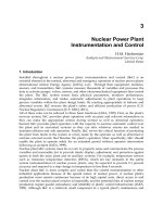
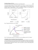
Fig. 1. Application of FPGA technology in the NPP I&Cs produced by RPC Radiy
1. Implementation of separate FPGA-based functions (devices)
Signals processing
(SP)
Control algorithms
(CA)
Actuation signals
(AS)
Diagnostics (D)
2. Implementation of FPGA-based control algorithms
SP CA AS
D
3. Implementation of FPGA-based control, processin
g
snd
communication functions
SP CA AS
D
– FPGA-based implementation of functions
– software (microprocessor)-based or other implementation
Multi-Version FPGA-Based Nuclear Power Plant I&C Systems: Evolution of Safety Ensuring
33
There are three stages of the evolution (Fig.1): from implementation of separate FPGA-based
functions in I&Cs (signals processing (SP), control algorithms (CA), actuation signals
formation (AS) and diagnostics (D)), stage 1, and implementation of FPGA-based CA, stage
2, to preferred implementation of FPGA-based SP-, CA-, AS-, D- and communication
functions, stage 3.
Analysis of industrial application experience of FPGAs in NPP I&Cs is described in
technical report prepared by EPRI (Naser, 2009).
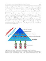
2.3 A law “negation of negation”: Stages of diversity approach implementation
evolution in NPP I&Cs
Interesting are the results of transformation of multi-version I&Cs for the last decades in
context of hardware-software-FPGA technologies development. There are a few diversity
implementation evolution stages in safety-critical NPP I&Cs, in particular, reactor trip
systems. Analysis of these stages allows formulating (or demonstrating truth) a law
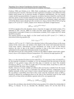
“negation of negation” (Kharchenko et al., 2009) (Fig.2):
- stage 1 (1970-1980s) – use of hardware (hard logic, HL)-based one-version systems and
transition from hardware (HW)-based systems with identical subsystems to systems
with hardware (HL)-based primary subsystem and software (microprocessor, MP)-
based secondary subsystem; it was the first “negation”;
- stage 2 (1990s) – use of primary and secondary subsystems with software (SW) diversity
(I&C platforms produced by Siemens, WH and other companies); example of multi-
version systems with software diversity is two-version system consisting of subsystems
developed using microprocessors Intel and Motorola (languages C and Ada); it
completed the first cycle of “negation of negation”;
- stage 3 (2000s, first half) – transition to FPGA-based primary and software-based
secondary subsystems with equipment, design and software diversity (first generation
of the I&C platforms produced by RPC Radiy); it was next “negation”;
- stage 4 (2000s, second half) – application of FPGA-oriented soft processors for primary
subsystem and FPGA project developed using HDL-oriented language (hard logic) for
creation of secondary subsystem (next generation of the I&C platform produced by
RPC Radiy); it completed the second cycle of “negation of negation”;
- stage 5 (beginning of 2010s) – application of different FPGAs (hard logic) produced by
different manufacturers (and other types of diversity) for primary and secondary
subsystems correspondingly; it is next “negation”.
What will be the next step? Probably, advancement of electronic technologies, in particular,
nanotechnologies, naturally dependable, safe and secure chips will create new perspectives
and possibilities for development of diversity-oriented decisions. Actel, Altera and others
companies inform about creating first chips called nano FPGAs allowing to develop fault-
tolerant projects using large-scale means.
3. Normative base and key challenges connected with diversity application in
NPP I&Cs
3.1 Analysis of diversity related standards
There are the following standards and guides contained requirements to diversity:
- IEC 61513: 2001. NPPs - I&Cs important to safety – general requirements for systems;
- IEC 60880: 2006. NPPs - I&Cs important to safety - SW aspects for computer-based
systems performing category A functions;
Nuclear Power – Control, Reliability and Human Factors
34
- IAEA NS-G-1.3: 2002. I&Cs important to safety in NPPs;
- IEEE std.7-4.3.2:1993. IEEE standard criteria for digital computers in safety systems of
NPPs;
Fig. 2. Stages of diversity approach implementation evolution in safety-critical NPP I&Cs
SW
1
(MP
1
)
SW
2
(MP
2
)
HW
(HL)
SW
(MP)
HW
(HL)
2000s
1990s
1980s
HW
(HL)
HW
(FPGA
i
)
SW
(MP)
FPGA
1
(HL)
FPGA
2
(IP -SW)
FPGA
1
(HL
1
)
FPGA
2
(HL
2
)
2010s
? ?
Multi-Version FPGA-Based Nuclear Power Plant I&C Systems: Evolution of Safety Ensuring
35
- NUREG/CR-6303:1993. Method for Performing Diversity and Defense-in-Depth
Analyses of Reactor Protection Systems;
- DI&C-ISG-02, Diversity and Defense-in-Depth Issues, Interim Staff Guidance, BTP 7-19,
Guidance for Evaluation of D&DiD In Digital I&C Systems (USA);
- NP 306.5.02/3.035: 2000. Requirement on nuclear and radiation safety to I&Cs
important to safety in NPPs (Ukraine), etc.
These standards contain general requirements concerning: systems which must/should be
developed using diversity approach (Reactor Trip Systems); types of diversity used to
develop NPP I&Cs and to decrease CCF probability; features of diversity implementation,
determination of types and volume of diversity; assessment (justification) of real level of
diversity in developed systems; drawbacks and benefits connected with the use of
diversity.
The standards are not enough detailed to make all necessary decisions concerning
diversity. It’s important to develop additional detailed techniques of assessing diversity
and choosing optimal kinds and volume of diversity according to criterion “safety-
reliability-cost”.
3.2 Key challenges
Main conclusions concerning FPGA-based MVS development and implementation
experience are the following:
FPGA-based multi-version I&Cs are used in NPPs during 6-8 last years, i.e. these systems
are new object of analysis and still more unique one;
FPGA technology gives additional possibilities to develop MVSs and ensure high safety and
reliability;
processes of FPGA project development are similar to processes of SW-based
project development. FPGA project product is similar to HW-based project product (hard
logic);
there are not any international standards determined requirements to use of diversity for
I&Cs development and application taking into account FPGA features.
Results of comparative analysis of challenges caused by development and application of
software- and FPGA-based multi-version systems are presented in Table 2.
4. Main concepts and models of multi-version computing
4.1 Taxonomy scheme of multi-version computing
A set of concepts concerning diversity may be united by general term “multi-version
computing” on the analogy with “dependable computing” (Avižienis et al., 2004). Multi-
version computing is a type of dependable computing organization based on use of
diversity approach. Taxonomy scheme of multi-version computing developed taking into
consideration concepts in this area described in international standards includes the
following elements (Kharchenko et al, 2009) (Fig.3).
Version is an option of the different realization of identical task (by use software,
hardware or FPGA-based products and life cycle processes); identical versions of
structure redundancy-based system are trivial. Version redundancy (VR) is a type of
product and process redundancy allowing to create different (non-trivial) versions;
product VR is realized jointly with structure, time and other types of non-version
redundancy.
Nuclear Power – Control, Reliability and Human Factors
36
Challenges Software-based multi-version I&C
FPGA-based
multi-version I&C
Detailed
standards
There are standards determining
general requirements to use of
diversity
There are no special
standards
Experience of
development and
operation
More 20 years 6-8 years
Trustworthiness
of diversity
assessment
Methods of expert-based, metrical
assessment, probabilistic methods
using SRGMs
Methods of expert-based,
metrical, probabilistic (RBD),
deterministic methods
Development of
MVSs
Choice of diversity kinds, generation
of really diverse software versions
Number of diversity kinds
increases
Verification of
MVSs
Verification activities volume are
significantly increased
Verification is more simple
due to simplifying of version
verification
Table 3. Key challenges for software-based and FPGA-based MVSs
Fig. 3. Taxonomy scheme of multi-version computing
Diversity or multiversity (MV) is a principle providing use of several non-trivial versions;
this principle means performance of the same function (realization of products or
processes) by two and more options and processing of data received in such ways for
checking, choice or formations of final or intermediate results and decision-making on
their further use.
Multi-version system (MVS) is a system in which a few versions-products are used; one-
version systems may be redundant but consists of a few trivial versions. Multi-diversion
system (МDVS) is MVS in which two or more VR types are applied. Multi-version
Version
Processes
Products
Multiversit
y
(diversit
y
)
МV principle
Version redundanc
y
(n,m) -version
system
Multi-version
system
Multi-version
system
Multi-version project
One-version
system
Strate
gy
of MV
Multi-version
technology
Diversity metric
Multi-version
life cycle
Multi-Version FPGA-Based Nuclear Power Plant I&C Systems: Evolution of Safety Ensuring
37
technology (MVT) is set of the interconnected rules and design actions in which in
accordance with МV strategy a few versions-processes leading to development of two or
more intermediate or end-products are used; thus for development of MVS should be used
МVТ, for development one-version systems can be used both multi-version and one-version
technology.
Multi-version project (MVP) is a project in which the multi-version technology is applied
(version redundancy of processes is used) leading to creation of one- or multi-version
system (realization of version redundancy of products). Strategy of diversity (MV) is a
collection of general criteria and rules defining principles of formation and selection of
version redundancy types and volume or/and choice of MVTs. Besides, important elements
of multi-version computing are concepts “multi-version life cycle”, “diversity metric”. More
detailed interpretation of these concepts will be done below.
4.2 Diversity type classification schemes
Different variants of diversity type classifications were described above. The analysis of the
considered classifications allows approving that:
- they are presented by classifications of mixed facet-hierarchical or matrix (network)
types;
- the NUREG-based classification presented in (Wood et al., 2009) is the most detailed
and systematic, though the principle of attributes orthogonality is not sustained in full
in it; for example, subsets of design and software, functional and signal version
redundancy are crossed and dependent;
- variety of product (system, hardware and software components) and of process
(technologies of development, testing and maintenance) version redundancy cause
complexity of VR selection and MVS development.
More general diversity type classification scheme is so-called “cube” of diversity described
by matrix MVR = vr
ijk
in three-dimensional space (Fig. 4). The scheme has coordinates:
stage of LC (i); level of project decisions (PD, j) and type of VR (project decision).
Example of two-space matrix presented a cut of “cube” for FPGA-based systems is shown
on the table 3. This table contains variants of joint application of one or two diversity types
(items 1.4.2-1.4.4, 2.3.3-2.3.8, 3.3.3-3.3.8, 4.2.4-4.2.15; for example, last combinations
correspond to 12 = 4 (kinds of EE diversity) х 3 (kinds of CASE-tool diversity) couples).
Fig. 4. Cube” of diversity-oriented decisions
…
…
T
y
pe of VR (PD)
LC stage
PD levels
vr
ijk
Nuclear Power – Control, Reliability and Human Factors
38
Stages of FPGA-
based I&C life
cycle
Kinds of versio
n
redundanc
y
1 Diversity of
electronic
elements (EE)
2 Diversity of
CASE-tools
3 Diversity of
project development
languages
4 Diversity of
scheme
specification (SS)
1 Development
of block-
diagrams
according with
signal formation
al
g
orithms
1.2.1 Different develo-
pers of CASE-tools
1.2.2 Different CASE-
tools kinds
1.2.3 Different CASE-
tools confi
g
urations
1.4.1 Different SSs
1.4.2-1.4.4 Combi-
nation of couples
of diverse CASE-
tools and SSs
2 Development
of program
models of signal
formation
algorithms in
CASE-tools
environment
2.2.1 Different deve-
lopers of CASE-tools
2.2.2 Different CASE-
tools kinds
2.2.3 Different CASE-
tools configurations
2.3.1
J
oint use of
graphical scheme
language and HDL
2.3.2 Different HDLs
2.3.3-2.3.8 Combi-
nation of diverse
CASE-tools and
HDLs
3 Integration of
program models
of signal
formation
algorithms in
CASE-tools
environment
3.2.1 Different deve-
lopers of CASE-tools
3.2.2 Different CASE-
tools kinds
3.2.3 Different CASE-
tools configurations
3.3.1
J
oint use of
graphical schemes
and HDL
3.3.2 Different HDLs
3.3.3 – 3.3.8 Combi-
nation of couples of
diverse CASE-tools
and HDLs
4
Implementation
of integrated
program model
in FPGA
4.1 Different
manufacturers
of EEs
4.2 Different
technologies of
EEs production
4.3 Different
families of EEs
4.4 Different
EEs of famil
y
4.2.1 Different deve-
lopers of CASE-tools
4.2.2 Different CASE-
tools kinds
4.2.3 Different CASE-
tools configurations
4.2.4-4.2.15 Combina-
tion of diverse CASE-
tools and EEs
Table 2. Matrix of diversity-oriented FPGA-based decisions
4.3 Models multi-version systems
One-version W(1) and multi-version W(n) systems are defined by 4 and 6 variables
(Kharchenko et al., 2010):
W(1) = {X, Y, Z. Ф}, (1)
W(n) = {X, Y, Z. Ф, V, }, (2)
where X, Y, Z – sets of input signals, internal conditions (states) and output signals
correspondingly; Ф = {
i
, i=1, , a} – a set of I&C functions (for examples, actuation
functions or algorithms of reactor trip system); V = {v
j
, j=1, , n} – a set of versions with
output signals Z
1
,…, Z
n
(or signals Z
id
, d = 1,…, n
i
; n
i
is a number of versions for function
i
;
i
~ v
j
= { v
ij
, j =1, ,n
i
}); = {
s
, s=1, , в} – mapping Z
i
Z.
Multi-Version FPGA-Based Nuclear Power Plant I&C Systems: Evolution of Safety Ensuring
39
If the function
i
is performed, local mapping is true:
s
:{z
i
(v
i1
), , z
i
(
i
in
v )}
(S)
i
Z . Taking
into account formulas (1) and (2), multi-version system and one-version system are
connected by relationship:
W(n) = {W(1), V,
}. (3)
System W(1) may be structure-redundant and contain usual means
for signals processing
from identical channels (versions). In this case card V=1. For system W(n) is true that:
j
= 1,a :
j
: n
i
>1.
Mapping
s
is generally described by: a subset of versions v
s
v
j
for receiving output signal
Z
i
; a vector
s
t
of version v
ij
initialization time (
s
t
= {t(v
i1
), , (
i
in
v )}); a mean of transforming
s
values z
i
(v
i1
), , z
i
(
i
in
v ) in output signal
S
i
Z . Hence,
s
:
s
= { vs,
s
t
,
s
} and
(S)
i
Z =
s
[z
i
(v
ij
),
s
t
], v
ij
v
s
.
There are the following means of transforming
s
: (a) the conjunctive, when
S
i
Z =Vz
i
(v
ij
); (b)
the time conjunctive, when
S
i
Z =Vz
i
(v
ij
)
ij
, where
ij
=1, if t=t(v
ij
), and if not
ij
=0; (c) the
majority, when
S
i
Z =М[z
i
(v
ij
)], where М is a majority function k out of l (or k out of n); (d) the
majority-weighted, when weights of versions
(v
ij
) are additionally defined on majorization;
(e) the functional, when
S
i
Z =f[z
i
(v
ij
)], where f - some function of transforming output signals
of every version.
The model (2) describes system with n versions that,
i
i1
nn
a
. This model does not take
into account the possibility of applying several diversity kinds. A set of version redundancy
kinds R={r
d
, d=1, , m} may be decomposed on subsets for versions of products v
prd
(t
j
) and
processes v
prc
(t
j
): R=(
j
R
prdj
) (
j
R
prcj
), where R
prdj
and R
prcj
– appropriate subsets.
Thus, different diversity kinds, r
R, are accumulated in final versions of a multi-version
system. It is described by special mapping
: R V. Mapping may be presented by
Boolean matrix
d
j
, d=1,m;
j
= 1,n , where
dj
=1, if diversity kind r
p
is used in version
v
j
, and if not
dj
= 0. Then multi-version system W(n,m) or multi-diversion system is
described by formula:
W(n,m) = { X, Y, Z, Ф, V,
, R, } = {W(n), R, } = {W(1), V, ,R, }. (4)
It is important to describe correspondence between a set of versions V and a set of
redundant channels С={c
q
, q=1, ,l}. This correspondence may be defined by mapping
Q:V
C. This mapping is presented by Boolean matrix Q =
jg
, d=1,m,
g=1,l
, where
gj
= 1, if version v
i
is realized by channel c
j
, and if not
gj
= 0. Then model of multi-version
(multi-diversion) system is the following:
W(n,m,l) = { X, Y, Z, Ф, V,
, R, , С, Q }= { W(n,m), С, Q }. (5)
MVSs with temporal redundancy and р iterations of algorithms are indicated as W(n,m,n,р)
dividing number of parallel (structural) versions n
c
, and sequential versions realized by
using one channel. Set Х may be decomposed for different versions if
Nuclear Power – Control, Reliability and Human Factors
40
Х =
j
j
X
, j
1
j
2
1,n , j
1
j
2
:
j
1
j
2
XX ,
j
1
j
2
XX =
.
Such MVSs are called multi-version systems with naturally divided input alphabet:
W
NХ
= { {Х
j
}, Y, Z, Ф, V, , R, , С, Q}. (6)
If versions process data presented in different notations, such MVSs are called multi-version
systems with artificially divided input alphabet WAХ. A special function-transformer Пх
(Пхj) should be specified in addition to alphabet Х :
W
NХ
= {X, {Пхj}, Y, Z, Ф, V, , R, , С, Q}. (7)
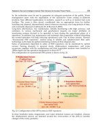
1
C
,
2
C
- the first and the second versions of a monitoring automaton;
1
U
,
2
U
-
the first and the second versions of a contril automaton;
dC
,
dU
,
d
- solver for union of two versions results.
Fig. 5. Architecture variants of two-version I&C systems
X
MCO
1
C
2
C
1
C
Z
2
C
Z
1
U
2
U
Z
1
Z
2
d
Z
a) two-versions system with full common diversity,
FO
X
MCO
1
C
2
C
1
C
Z
2
C
Z
1
U
2
U
Z
1
Z
2
dU
Z
b) two-versions system with full separate diversity,
FS
Z
C
dC
X
MCO
1
C
2
C
1
C
Z
2
C
Z
Z
C
U
Z
c) two-versions system with partial diversity (for
C
),
PC
dC
X
MCO
1
U
2
U
z
C
dU
Z
d) two-versions system with partial diversity (for
U
),
PU
C
Z
1
Z
2
Multi-Version FPGA-Based Nuclear Power Plant I&C Systems: Evolution of Safety Ensuring
41
Besides, I&Cs performing safety-critical functions may be represented by a composition of
two interconnected subsystems – monitoring (checking) subsystem and control subsystem
(monitoring and control automata). Monitoring automaton
C
analyses output signals X
from monitoring and control object (MCO) and forms its status code Z
C
.
Control automaton
U
forms control signals Z in accordance with signals Z
C
. Several options
of MVS architectures are possible for a FPGA-based I&Cs. Those options may be classified
according with such attributes (see Fig. 5):
degree of diversity coverage (I&Cs with a full
F
and partial
P
diversity);
diversity depth (I&Cs with a common
O
and separate
S
diversity); it should be noted that
this feature is applicable only to full system diversity.
4.4 Models of multi-version life cycle and technology
A model of MVS life cycle (or multi-version LC model) is based on operations of version
generation G, aggregation and selection U at various stages (Kharchenko et al., 2007).
Example of the two-version life cycle model is shown on Fig. 6 taking to account some
FPGA-oriented design features (V
ij
are different versions obtained on different stage of
development) (Prokhorova et al., 2008).
Fig. 6. FPGA-system multi-version life cycle
In general case I&C system LC is a sequence of N stages. At each i-th stage of a multi-version
I&C system LC Mi of diversity types may be applied. From Mi, i = 1, ,N; diversity types only
a single j-th type, j = 1, ,Mi, may be selected. Besides, at each i-th stage of LC a single-version
development technology may be selected. Each j-th diversity type at each i-th LC stage is
characterized by two indices: diversity metrics (depth) dij and cost of respective diversity type
application (cost increase as compared to single-version option of each i-th LC stage).
V
1
G
2
V
21
V
22
G
3
U
2
G
4
V
41
V
42
U
4
V
31
V
32
U
3
Requirements
specification
Models design
(different
architectures)
Development
(different developers
and lan
g
ua
g
es)
Compilatio
n
V
51
V
52
U
5
G
6
V
61
V
62
U
6
G
7
V
71
V
72
U
7
V
final1
V
final2
Independent version
testing (different executors
snd testing methods
Cross-testing
of versions
The choice of better
variant and the
firmware load
Selected
versions
G
5
Nuclear Power – Control, Reliability and Human Factors
42
Thus, a set of solutions on selection of diversity kind is described by two matrices: diversity
metrics values D =
d
ij
and cost values С = с
ij
. Hence MVS LC may be presented as a
bipolar N-level graph (Fig.7) called graph of multi-version technologies (Sklyar
&Kharchenko, 2007). MVT corresponds to non-zero way in this graph.
Algorithms of MVT (optimal way in the graph) selection according with criteria “diversity
(safety)-reliability-cost” are described in (Kharchenko&Sklyar, 2008).
Fig. 7. Graph of MVTs
5. Assessment of multi-version FPGA-based systems safety
5.1 General approach to assessment
Assessment of diversity level and MVS safety is based on the following basic procedures
analysis and evaluation:
-
check-list-based analysis of applicable diversity types (CLD); initial data for the CLD
analysis are I&C design and documentation, a table of diversity types (subtypes) was
developed in advance; a result of the CLD analysis is a formalized structured
information about used diversity types and subtypes in analyzed I&C system;
-
metric-based assessment of diversity (MAD); initial data for the MAD procedure are
results of the CLD analysis and values of metrics and weight coefficients for diversity
types (subtypes) used in I&C systems; a result of the MAD assessment is a value of
general diversity metric;
-
Reliability Block Diagram (RBD) and Markovian model (MM)-based assessment taking
into account results of MAD.
5.2 Stages of assessment
The main stages and operations of diversity analysis and MVS assessment depend on the
type of the evaluated system. The first stage is a Check-list-based analysis of MVS design
and documentation. This stage contains two operations:
1.
Analysis of I&C specification and requirements to system, definition of system safety
class; requirements to diversity (necessary for diversity application);
2.
Analysis of I&C design and development process that involves activities: (a)
identification of MVS types: which of the subsystems are FPGA-based and which are
software and microprocessor-based; (b) identification of product diversity; for FPGA-
based MVSs: manufacturer of chips; FPGA technology; FPGA families; FPGA chips,
languages; tools, etc); (c) identification of process diversity kinds.
1
d
ij
,с
ij
0,0
2i
N
0,0 0,0 0,0
Multi-Version FPGA-Based Nuclear Power Plant I&C Systems: Evolution of Safety Ensuring
43
Results of analysis are entered in a check-list in accordance with rule Yes (if corresponding
diversity type is used in a system) / No (in opposite case) and is presented as a n-bit
Boolean vector.
The second stage is a metric-based assessment of diversity. This stage contains two
operations:
1.
Determination of metric values for different types of applied diversity, i.e. performing
two activities: (a) determination of metric values (local diversity metrics μ
i
for diversity
type d
i
and local diversity metrics μ
ij
for diversity subtype d
ij
); the metric values may be
predefined; (b) correction of metric values in accordance with development and
operation experience.
2.
Calculation of general diversity metric μ for a system: (a) determination (correction) of
weight coefficients ω
i
(ω
ij
) of metrics (taking into account multi-diversity aspect); sum of
weight coefficients ω
i
(ω
ij
) is equal 1; (b) convolution (additive or more complex) of
metrics and calculating value of general diversity metric μ = Σ ω
i
Σ ω
ij
μ
ij
, i = 1,…, n; j =
1,…n
i
.
Thus, result of this stage is a value of general diversity metric μ, which is some
approximation of
, and can characterize the diversity effect on CCF probability.
The third stage is a probabilistic RBD- or MM-based (RDM) assessment of MVS reliability
and safety. Initial data for the RDM procedure are I&C design and documentation, results of
the CLD and MAD analysis; results of the RDM procedure are values of safety and
dependability indicators. Detailed description of the RDM procedure is given in
(Kharchenko et al., 2004).
6. Implementation of FPGA-based safety-critical NPP I&Cs
6.1 General description of the FPGA-based RADIY
TM
platform
The platform RADIY
TM
produced by RPC Radiy is an example of a dependable and scalable
FPGA-based I&C platform ensuring possibility of development of multi-version systems.
Dependability assurance feature of the I&C platform RADIY
TM
is multi-diversity
implementation through the following diversity types: equipment diversity is provided by
different electronic components, different programmable components (FPGAs and
microcontrollers) and different schemes of units; software diversity is provided by different
programming languages and different tools for development and verification; life cycle
(human) diversity is provided by different teams of developers.
Scalability of the I&C platform RADIY
TM
permits to produce different types of safety-
critical systems without essential changing of hardware and software components. The
I&C platform RADIY
TM
provides the following types of scalability: scalability of system
functions types, volume and peculiarities by changing quantity and quality of sensors,
actuators, input/output signals and control algorithms; scalability of dependability
(safety integrity) by changing a number of redundant channel, tiers, diagnostic and
reconfiguration procedures; scalability of diversity by changing types, depth and criteria
of diversity choice.
The FPGA-based I&C RADIY
TM
platform comprises both upper and lower levels
(Kharchenko&Sklyar, 2008). The upper level has been created on purchased IBM-compatible
industrial workstations. The software for the upper level RADIY
TM
platform was developed
by RPC Radiy and is loaded on the workstations. The functions of the upper level
workstations are the following: receipt of process and diagnostic information; creation of