Solar Cells Thin Film Technologies Part 1 docx
Bạn đang xem bản rút gọn của tài liệu. Xem và tải ngay bản đầy đủ của tài liệu tại đây (688.45 KB, 30 trang )
SOLAR CELLS –
THIN-FILM TECHNOLOGIES
Edited by Leonid A. Kosyachenko
Solar Cells – Thin-Film Technologies
Edited by Leonid A. Kosyachenko
Published by InTech
Janeza Trdine 9, 51000 Rijeka, Croatia
Copyright © 2011 InTech
All chapters are Open Access distributed under the Creative Commons Attribution 3.0
license, which permits to copy, distribute, transmit, and adapt the work in any medium,
so long as the original work is properly cited. After this work has been published by
InTech, authors have the right to republish it, in whole or part, in any publication of
which they are the author, and to make other personal use of the work. Any republication,
referencing or personal use of the work must explicitly identify the original source.
As for readers, this license allows users to download, copy and build upon published
chapters even for commercial purposes, as long as the author and publisher are properly
credited, which ensures maximum dissemination and a wider impact of our publications.
Notice
Statements and opinions expressed in the chapters are these of the individual contributors
and not necessarily those of the editors or publisher. No responsibility is accepted for the
accuracy of information contained in the published chapters. The publisher assumes no
responsibility for any damage or injury to persons or property arising out of the use of any
materials, instructions, methods or ideas contained in the book.
Publishing Process Manager Sandra Bakic
Technical Editor Teodora Smiljanic
Cover Designer Jan Hyrat
Image Copyright inacio pires, 2011. Used under license from Shutterstock.com
First published October, 2011
Printed in Croatia
A free online edition of this book is available at www.intechopen.com
Additional hard copies can be obtained from
Solar Cells – Thin-Film Technologies, Edited by Leonid A. Kosyachenko
p. cm.
ISBN 978-953-307-570-9
free online editions of InTech
Books and Journals can be found at
www.intechopen.com
Contents
Preface IX
Chapter 1 Thin-Film Photovoltaics
as a Mainstream of Solar Power Engineering 1
Leonid A. Kosyachenko
Chapter 2 Enhanced Diffuse Reflection of Light by Using
a Periodically Textured Stainless Steel Substrate 39
Shuo-Jen Lee and Wen-Cheng Ke
Chapter 3 Low Cost Solar Cells Based on Cuprous Oxide 55
Verka Georgieva, Atanas Tanusevski and Marina Georgieva
Chapter 4 Application of Electron Beam Treatment
in Polycrystalline Silicon Films Manufacture for Solar Cell 77
L. Fu
Chapter 5 Electrodeposited Cu
2
O Thin Films
for Fabrication of CuO/Cu
2
O Heterojunction 89
Ruwan Palitha Wijesundera
Chapter 6 TCO-Si Based Heterojunction Photovoltaic Devices 111
Z.Q. Ma
and B. He
Chapter 7 Crystalline Silicon Thin Film Solar Cells 137
Fritz Falk and Gudrun Andrä
Chapter 8 Architectural Design Criteria for Spacecraft Solar Arrays 161
Antonio De Luca
Chapter 9 Power Output Characteristics
of Transparent a-Si BiPV Window Module 187
Jongho Yoon
Chapter 10 Influence of Post-Deposition
Thermal Treatment on the Opto-Electronic
Properties of Materials for CdTe/CdS Solar Cells 209
Nicola Armani, Samantha Mazzamuto and Lidice Vaillant-Roca
VI Contents
Chapter 11 Chemical Bath Deposited CdS for CdTe
and Cu(In,Ga)Se
2
Thin Film Solar Cells Processing 237
M. Estela Calixto, M. L. Albor-Aguilera, M. Tufiño-Velázquez,
G. Contreras-Puente and A. Morales-Acevedo
Chapter 12 Innovative Elastic Thin-Film Solar Cell Structures 253
Maciej Sibiński and Katarzyna Znajdek
Chapter 13 Computer Modeling of Heterojunction
with Intrinsic Thin Layer “HIT” Solar Cells:
Sensitivity Issues and Insights Gained 275
Antara Datta and Parsathi Chatterjee
Chapter 14 Fabrication of the Hydrogenated Amorphous Silicon
Films Exhibiting High Stability Against Light Soaking 303
Satoshi Shimizu, Michio Kondo and Akihisa Matsuda
Chapter 15 Analysis of CZTSSe Monograin Layer Solar Cells 319
Gregor Černivec, Andri Jagomägi and Koen Decock
Chapter 16 Large Area a-Si/μc-Si Thin Film Solar Cells 335
Fan Yang
Chapter 17 Novel Deposition Technique for Fast
Growth of Hydrogenated Microcrystalline
Silicon Thin-Film for Thin-Film Silicon Solar Cells 359
Jhantu Kumar Saha and Hajime Shirai
Chapter 18 Chemical Surface Deposition of CdS
Ultra Thin Films from Aqueous Solutions 381
H. Il’chuk, P. Shapoval and V. Kusnezh
Chapter 19 Development of Flexible Cu(In,Ga)Se
2
Thin Film Solar Cell by Lift-Off Process 405
Yasuhiro Abe, Takashi Minemoto and Hideyuki Takakura
Chapter 20 What is Happening
with Regards to Thin-Film Photovoltaics? 421
Bolko von Roedern
Chapter 21 Spectral Effects on CIS Modules
While Deployed Outdoors 441
Michael Simon and Edson L. Meyer
Preface
Solar cells are optoelectronic devices that convert the energy of solar radiation directly
into electricity by the photovoltaic (PV) effect. Assemblies of cells electrically
connected together are known as PV modules, or solar panels. The photovoltaic effect
was first recognized in the 19th century but the modern PV cells were developed in
the mid-1950s. The practical application of photovoltaics started to provide energy for
orbiting satellites. Today PV installations may be ground-mounted or built into the
roof or walls of buildings, and are used for electric power in boats, cars, water pumps,
radio stations, and more. The majority of PV modules are used for grid connected
power generation. More than 100 countries use photovoltaics. Solar power is
pollution-free during use. Due to the growing demand for renewable energy sources,
the manufacturing of solar cells and PV arrays has advanced considerably in recent
years.
Solar cells and modules based on crystalline and polycrystalline silicon wafers, the
representatives of the so-called first generation of solar cells, dominate the
photovoltaic today and demonstrate high growth rates in the entire energy sector.
Nevertheless, despite the relatively high annual growth, the contribution of
photovoltaics in the global energy system is small. The reason for this lies in a large
consumption of materials and energy, high labor intensiveness and, as a consequence,
a low productivity and high cost of modules with acceptable PV conversion efficiency
for mass production. Driven by advances in technology and increases in
manufacturing scale, the cost of photovoltaics has declined steadily since the first solar
cells were manufactured. For decades, an intensive search for cheaper production
technology of silicon solar cells is underway. In many laboratories around the world,
extensive research to improve the efficiency of solar cells and modules without
increasing the cost of production are carried out. A large variety of solar cells, which
differ depending on the materials used, PV structure, design and even the principle of
PV conversion are designed to date. Among the radical ways to reduce the cost of
solar modules and to increase drastically the volume of their production is the
transition to thin-film technology and the use of a cheap large-area substrate (glass,
metal foil, plastic).
Amorphous silicon (a-Si) was the first material for commercial thin-film solar cells
with all their attractiveness to reduce consumption of absorbing material, increase in
X Preface
area and downturn in price of modules. Quite common in commercial solar cells are
the multi-layer structures based on a-Si. It seemed that the tandem structure, a
representative of the third generation of solar cells, opened the prospect of developing
efficient and low-cost solar cells. Special place in the thin-film photovoltaics is the so-
called micromorph solar cells, which are closely related to the a-Si. However, the use
of a-Si and micromorph solar cells is limited preferably to areas, where low cost is
more important than the efficiency of photoelectric conversion such as consumer
electronics and building-integrated photovoltaics (BIPV).
Unquestionable leaders in thin-film technologies are solar cells on CuInxGa1-xSe2
(CIGS) and CdTe, the representatives of the so-called second generation photovoltaics.
For a long time, CIGS have been considered as promising material for high-
performance thin-film solar cells and fabrication of monolithically interconnected
modules intended for cost-effective power generation. As a result of research, aimed to
reducing the cost of CIGS solar modules, several companies developed the commercial
CIGS solar modules and initiated their large-scale production. In the early years of the
21st century, the technology and manufacturing of solar modules based on CdTe,
which could compete with silicon counterparts, was also developed. It should be
emphasized that the growth rates of CdTe module production over the last decade are
the highest in the entire solar energy sector.
Dye-sensitized solar cells (DSSCs) are considered to be extremely promising because
they are made of low-cost materials with simple inexpensive manufacturing
procedures and can be engineered into flexible sheets. Organic solar cells attract the
attention also by the simplicity of technology leading to inexpensive, large-scale
production for the future. This type of cells as well as multi-junction structures based
on a-Si and micromorph silicon can be assigned to the so-called third generation solar
photovoltaics. GaAs based multi-junction devices were originally designed for special
applications such as satellites and space exploration. To date they are the most efficient
solar cells.
Four-volume edition under the joint name of "Solar cells" encompasses virtually all
aspects of photovoltaics. Research and development in the field of thin-film solar cells
based on CIGS, CdTe, amorphous, micro- and polycrystalline silicon are presented in
the first volume with the subtitle "Thin-film technology". The second volume subtitled
«Dye-Sensitized Devices» is devoted to the problems of developing high-efficiency
solar modules using low-cost materials with simple inexpensive manufacturing
processes. The third volume subtitled « Silicon Wafer-Based Technologies» includes
the chapters that present the results of research aimed ultimately to reduce
consumption of materials, energy, labor and hence cost of silicon solar modules on
wafer or ribbon silicon. Chapters that present new scientific ideas and technical
solutions of photovoltaics, new methods of research and testing of solar cells and
modules have been collected in the forth volume subtitled «New Aspects and
Solutions».
Preface XI
It is hoped that readers will find many interesting and useful material in all four
volumes of «Solar Cells» covering highly topical issues of photovoltaics.
From the above it follows that the first book of this four-volume edition is dedicated to
one of the most promising areas of photovoltaics, which has already reached a large-
scale production of the second-generation thin-film solar modules and has resulted in
building the powerful solar plants in several countries around the world. Thin-film
technologies using direct-gap semiconductors such as CIGS and CdTe offer the lowest
manufacturing costs and are becoming more prevalent in the industry allowing to
improve manufacturability of the production at significantly larger scales than for
wafer or ribbon Si modules. It is only a matter of time before thin films like CIGS and
CdTe would replace wafer-based silicon solar cells as the dominant photovoltaic
technology. Photoelectric efficiency of thin-film solar modules is still far from the
theoretical limit. The scientific and technological problems of increasing this key
parameter of the solar cell are discussed in several chapters of this volume.
The editor addresses special thanks to the contributors for their initiative and high
quality work, and to the technical editors that conveyed the submitted chapters into a
qualitative and pleasant presentation.
Professor, Doctor of Sciences, Leonid A. Kosyachenko
National University of Chernivtsi
Ukraine
1
Thin-Film Photovoltaics
as a Mainstream of Solar Power Engineering
Leonid A. Kosyachenko
Chernivtsi National University
Ukraine
1. Introduction
Provision of energy is one of the most pressing problems facing humanity in the 21st
century. Without energy, it is impossible to overcome the critical issues of our time.
Industrial world suggests continuous growth in energy consumption in the future.
According to the U.S. Department of Energy, the world's generating capacity is now close to
18 TW. The main source of energy even in highly developed countries is fossil fuel, i.e. coal,
oil and natural gas. However, resources of fossil fuel are limited, and its production and
consumption irreversibly affect the environmental conditions with the threat of catastrophic
climate change on Earth. Other energy sources, particularly nuclear energy, are also used
that would fully meet in principle the energy needs of mankind. Capacity of existing nuclear
reactors (nearly 450 in the world) is 370 GW. However, increasing their capacity up to 18 TW
or about 50 times (!), is quite problematic (to provide humanity with electric energy, the capacity
of nuclear power should be increased about 10 times). Resources of hydroelectric, geothermal,
wind energy, energy from biofuels are also limited. At the same time, the power of solar
radiation of the Earth's surface exceeds the world's generating capacity by more than 1000
times. It remains only to master this accessible, inexhaustible, gratuitous and nonhazardous
source of energy in an environmentally friendly way.
Solar energy can be converted into heat and electricity. Different ways of converting
sunlight into electricity have found practical application. The power plants, in which water
is heated by sunlight concentrating devices resulting in a high-temperature steam and
operation of an electric generator, are widespread. However, solar cells are much more
attractive due to the direct conversion of solar radiation into electricity. This is the so-called
photovoltaics. Under the conditions of the growing problems of global warming,
photovoltaics is the most likely candidate to replace fossil fuels and nuclear reactors.
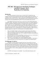
2. Silicon solar cells
Over the decades, solar modules (panels) based on single-crystalline (mono-crystalline, c-Si),
polycrystalline (multi-crystalline, mc-Si), ribbon (ribbon-Si) and amorphous (a-Si) silicon are
dominant in photovoltaics (Fig. 1).
In recent years, photovoltaics demonstrates high growth rates in the entire energy sector.
According to the European Photovoltaic Industry Association , despite the global financial
and economic crisis, the capacity of installed solar modules in the world grew by 16.6 GW in
Solar Cells – Thin-Film Technologies
2
Other
semiconductors
7 %
a-Si
5 %
c-Si
48 %
mc-Si
38 %
Ribbon Si
2 %
Fig. 1. Distribution of capacity of photovoltaic energy in the world.
2010, and their total capacity reached ~ 40 GW, that is almost 8 times more than in 2005. The
growth rate of the photovoltaic energy for the next 4-5 years is expected to be quite high. In
2014, capacity of installed modules will be about 14 GW and 30 GW according to the
pessimistic and optimistic forecast, respectively. Nevertheless, despite the relatively high
annual growth, the contribution of semiconductor solar cells in the global energy system is
small (less than 0.3%!), and the prospects for desired rapid development of photovoltaics are
not reassuring (Fig. 2). The contribution of Si photovoltaic solar power plants in generation
capacity in the world will reach ~ 1% only in the years 2018-2020, and may exceed 10% in
the years 2045-2050 (EPIA, 2011; EUR 24344 PV, 2010; Jager-Waldau, 2010). Analysts do not
accept the development of the PV scenario shown by the dashed line in Fig. 2. Thus, solving
the energy problems by developing Si photovoltaics seems too lengthy.
1
The reason for the slow power growth of traditional silicon solar modules lies in a large
consumption of materials and energy, high labor intensiveness and, as a consequence, a low
productivity and high cost of modules with acceptable photovoltaic conversion efficiency
for mass production (16-17 and 13-15% in the case of single-crystalline and polycrystalline
material, respectively) (Szlufcik et al., 2003; Ferrazza, 2003).
2
The problem is fundamental and
lies in the fact that silicon is an indirect semiconductor and therefore the total absorption
needs its significant thickness (up to 0.5 mm and more). As a result, to collect the charge
photogenerated in a thick absorbing layer, considerable diffusion length of minority carriers
(long lifetime and high mobility) and, therefore, high quality material with high carrier
diffusion length of hundreds of micrometers are required.
Estimating the required thickness of the semiconductor in solar cells, one is often guided by
an effective penetration depth of radiation into the material
–1
, where
is the absorption
coefficient in the region of electronic interband transitions. However, the value of
varies
1
In the European Union, these rates are much higher. Now the cumulative power of solar modules is
1.2% and, by 2015 and 2020, will rise to 4-5% and 6-12% of the EU’s electricity demand, respectively.
2
A lot of effort has been undertaken to increase the efficiency of silicon solar cells above 20-24% but
improvements are reached only with the help of cost-intensive processes, which usually cannot be
implemented into industrial products (Koch et al., 2003).
Thin-Film Photovoltaics as a Mainstream of Solar Power Engineering
3
1990 2010 2030
10
4
2050
10
3
10
2
10
0
10
1
Years
Cumulative capacity (GW)
Fig. 2. Evolution of world cumulative installed PV capacity until 2050: historical data,
, , forecasts (EPIA, 2011; EUR 24344 PV, 2010; Hegedus & Luque, 2011).
rather widely, especially in the indirect semiconductor, and solar radiation is distributed
over the spectrum in a complicated manner (Fig. 3(a)). Therefore, the absorptive capacity
(absorptivity) of the material, used in solar cell, can be described by a certain integral
characteristic, which takes into account the absorption spectrum of the material and the
spectral distribution of solar radiation. For a structure with flat surfaces, the integral
absorption ability of the radiation, which has penetrated into the material (certain part of
radiation is reflected from the front surface), can be represented as
11
1
1
22
2
ii ii
i
i
ii
i
i
d
Ad
exp
()
, (1)
where Φ
і
is the spectral power density of solar radiation at the wavelength
і
under
standard solar irradiation AM1.5 shown in Fig. 3(a),
і
is the spacing between neighboring
wavelengths in Table 9845-1 of the International Organization for Standardization (Standard
ISO, 1992), and
і
is the absorption coefficient at wavelength
і
. The summation in Eq. (1) is
made from
300 nm to
=
g
= hc/E
g
, since at wavelengths
shorter than 300 nm,
terrestrial radiation of the Sun is virtually absent, and when
g
, radiation is not absorbed
in the material with the generation of electron-hole pairs.
Fig. 3(b) shows the dependences of absorptivity of solar radiation A of single-crystalline
silicon on the thickness of the absorber layer d calculated by Eq. (1).
As seen in Fig. 3(b), in crystalline silicon, the total absorption of solar radiation in the
fundamental absorption region (hv E
g
) occurs when d is close to 1 cm (!), and 95% of the
radiation is absorbed at a thickness of about 300 m. More absorption can be achieved by using
the reflection of light from the rear surface of the solar cell, which is usually completely
Solar Cells – Thin-Film Technologies
4
200 400 600 800 1000 1200
10
7
0
100
Φ(
) mWcm
–2
m
–1
50
150
(
n
m
)
α
АМ1.5
(
Globa
l
)
10
5
10
4
10
3
10
2
10
1
10
0
10
6
(a)
(cm
–1
)
Φ(
)
1.0 10 10
2
0
0.2
0.4
0.6
0.8
1.0
10
3
10
–1
d (
m)
Absor
p
tivit
y
А
(
d
)
(
b
)
10
4
Fig. 3. (a) – Power spectral density of the total solar radiation Φ under AM1.5 conditions and
the absorption curve
(λ) for crystalline silicon. (b) – Dependence of absorptivity of solar
radiation in the hv ≥ E
g
spectral range on the absorber layer thickness d for crystalline silicon.
The dashed line shows the absorptivity of a silicon wafer taking into account 100% reflection
from its rear surface.
covered with metal. If in the ideal case, the reflectivity of light from the rear surface is unity,
the absorption of the plate will be such as if its thickness is twice as much. In this case, 95%
of the radiation is absorbed by the plate of 150 m thickness.
Of course, it has to be rejected to use silicon wafers of thickness a few millimeters, so that
the absorption of solar radiation was complete. Many companies producing silicon modules
Thin-Film Photovoltaics as a Mainstream of Solar Power Engineering
5
agreed on a compromise thickness of 150-250 m, when about 93% of solar radiation with
photon energy hv E
g
is absorbed or about 94% when the rear surface of the solar cell is
mirror (Szlufcik et al., 2003; Ferrazza, 2003).
3
Deficiency of absorption in the material offsets
by the creation of a special profile on surfaces (texturing) and by other ways. Needless to
say, an anti-reflective coating is applied to reduce significantly the reflection from the front
surface because over 30% of the radiation is reflected from a flat silicon surface.
Production of solar modules based on silicon wafers involves a lot of stages (Hegedus &
Luque, 2011). The so-called metallurgical grade (MG) silicon is obtained from quarzite (SiO
2
)
with charcoal in a high-temperature arc furnace. Then MG silicon is highly purified commonly
by a method developed by the Siemens Company consisting of the fractional distillation of
chlorosilanes. Finally, chlorosilanes are reduced with hydrogen at high temperatures to
produce the so-called semiconductor grade (SG) silicon. By recrystallizing such
polycrystalline silicon, single-crystalline Si ingots are often grown by the Czochralski (Cz) or
the floating-zone (FZ) techniques adapted from the microelectronics industry. This is
followed by cutting (slicing) the ingot into wafers, of course, with considerable waste. It
should be noted that the cost of silicon purification, production of ingots, slicing them into
wafers constitute up to 40-55% of the cost of solar module.
Manufacture of conventional silicon solar cell also includes a number of other operations.
Among them, (i) chemical etching wafers to provide removal of the layer damaged during
slicing and polishing; (ii) high-temperature diffusion to create a p-n junction; (iii) anisotropic
etching to build a surface structure with random pyramids that couples the incoming light
more effectively into the solar cell; (iv) complicated procedure of applying full area and
grid-like ohmic contacts to p- and n-type regions provided a minimum of electrical and
recombination losses (contacts in silicon solar cells are often made by screen-printing metal
paste, which is then annealed at several hundred degrees Celsius to form metal electrodes),
etc. (Mauk, et al., 2003). Once the cells are manufactured they are assembled into modules
either in the cell factories or in module assembly factories that purchase cells from variety
cell factories (Hegedus & Luque, 2011). All that complicates the manufacturing technology
and, hence, reduces the productivity and increases the cost of solar modules.
Summing up, one should again emphasize that single-crystalline Si modules are among the
most efficient but at the same time the most expensive since they require the highest purity
silicon and involve a lot of stages of complicated processes in their manufacture.
For decades, an intensive search for cheaper production technology of silicon solar cells is
underway. Back in the 1980's, a technology of material solidification processes for
production of large silicon ingots (blocks with weights of 250 to 300 kg) of polycrystalline
(multicrystalline) silicon (mc-Si) has been developed (Koch et al., 2003). In addition to
lower cost manufacturing process, an undoubted advantage of mc-Si is the rational use of
the material in the manufacture of solar cells due to the rectangular shape of the ingot. In the
case of a single-crystalline ingot of cylindrical form, the so-called "pseudo-square" wafers with
rounded corners are used, i.e. c-Si modules have some gaps at the four corners of the cells).
Polycrystalline silicon is characterized by defects caused by the presence of random grains of
crystalline Si, a significant concentration of dislocations and other crystal defects
(impurities). These defects reduce the carrier lifetime and mobility, enhance recombination
of carriers and ultimately decrease the solar cells efficiency. Thus, polysilicon-based cells
3
Further thinning of silicon is also constrained by the criteria of mechanical strength of a wafer as well
as the handling and processing techniques (silicon is brittle).
Solar Cells – Thin-Film Technologies
6
are less expensive to produce single-crystalline silicon cells but are less efficient. As a result,
cost per unit of generated electric power ("specific" or “relative” cost) for c-Si and mc-Si
modules is practically equal (though the performance gap has begun to close in recent
years). The polysilicon-based cells are the most common solar modules on the market being
less expensive than single-crystalline silicon.
A number of methods for growing the so-called ribbon-Si, i.e. a polycrystalline silicon in
the form of thin sheets, is also proposed. The advantages of ribbon silicon are obvious, as it
excludes slicing the ingot into thin wafers, allowing material consumption to reduce
roughly halved. However, the efficiency of ribbon-Si solar cells is not as high as of mc-Si cells
because the need of high quality material with the thickness of the absorber layer of 150-250
m and, hence, with high carrier diffusion lengths of hundreds of micrometers remains
(Hegedus & Luque, 2011). Nevertheless, having a lower efficiency, ribbon-Si cells save on
production costs due to a great reduction in waste because slicing silicon crystal into the
thin wafers results in losses (of about 50%) of expensive pure silicon feedstock (Koch et al.,
2003). Some of the manufacturing technologies of silicon ribbons are introduced into
production, but their contribution to the Si-based solar energy is negligible (Fig. 1). The cost
of ribbon-Si modules, as well as other types of silicon solar modules, remains quite high.
Many companies are developing solar cells that use lenses or/and mirrors to concentrate a
large amount of sunlight onto a small area of photovoltaic material to generate electricity.
This is the so-called concentrated photovoltaics. The main gain that is achieved through the
involvement of concentrators is to save material. This, however, does not too reduce the cost
of the device, because a number of factors lead to higher prices. (i) For the concentration of
radiation, an optical system is necessarily required, which should maintain a solar cell in
focus by the hardware when the sun moves across the sky. (ii) With a significant increase in
the intensity of the radiation, the photocurrent also increases significantly, and the electrical
losses rapidly increase due to voltage drop across the series-connected resistance of the bulk
of the diode structure and contacts. (iii) For the removal of heat generated by irradiation that
decreases the efficiency of photovoltaic conversion, it is necessary to use copper heatsinks.
(iv) The requirements to quality of the solar cell used in the concentrator considerably
increase. (v) Using concentrators, only direct beam of solar radiation is used, which leads to
losing about 15% efficiency of solar module.
Nevertheless, today the efficiency of solar concentrators is higher compared to conventional
modules, and this trend will intensify in the application of more efficient solar devices. In
2009, for example, the power produced in the world using solar energy concentration did
not exceed 20-30 MW, which is ~ 0.1% of silicon power modules (Jager-Waldau, 2010).
According to experts, concentrator market share can be expected to remain quite small
although increasing by 25% to 35% per year (Von Roedern, 2006).
In general, in this protracted situation, experts and managers of some silicon PV companies
have long come to conclusion that there would be limits to growing their wafer (ribbon)
silicon business to beyond 1 GW per year by simply expanding further (Von Roedern, 2006).
All of these companies are researching wafer-Si alternatives including the traditional thin-
film technologies and are already offering such commercial thin-film modules.
Concluding this part of the analysis, one must agree, nevertheless, that wafer and ribbon
silicon technology provides a fairly high rate of development of solar energy. According to
the European Photovoltaic Industry Association (EPIA), the total installed PV capacity in the
world has multiplied by a factor of 27, from 1.5 GW in 2000 to 39.5 GW in 2010 – a yearly
growth rate of 40% (EPIA, 2011).
Thin-Film Photovoltaics as a Mainstream of Solar Power Engineering
7
Undoubtedly, solar cells of all types on silicon wafers, representatives of the so-called first
generation photovoltaics, will maintain their market position in the future. In hundreds of
companies around the world, one can always invest (with minimal risk) and implement the
silicon technology developed for microelectronics with some minor modifications (in
contrast, manufacturers of thin-film solar modules had to develop their “own”
manufacturing equipment). Monocrystalline and polycrystalline wafers, which are used in
the semiconductor industry, can be made into efficient solar cells with full confidence. It is
also important that silicon is very abundant, clean, nontoxic and very stable. However, due to
limitations in production in large volumes of silicon for solar modules, which are both
highly efficient and cost-effective, often-expressed projections for desirable significant increase in
their contribution to the world energy system in the coming years are highly questionable.
3. Thin-film solar cells
Among the radical ways to reduce the cost of solar modules and to increase drastically the
volume of their production is the transition to thin-film technology, the use of direct-gap
semiconductors deposited on a cheap large-area substrate (glass, metal foil, plastic).
We start with the fact that the direct-gap semiconductor can absorb solar radiation with a
thickness, which is much smaller than the thickness of the silicon wafer. This is illustrated
by the results of calculations in Fig. 4 similar to those performed for the single-crystalline
silicon shown in Fig. 2. Calculations were carried out for direct-gap semiconductors, which
is already used as absorber layers of solar modules: a-Si, CdTe, CuInSe
2
and CuGaSe
2
.
As expected, the absorptivity of solar radiation of direct-gap semiconductors in general is
much stronger compared to crystalline silicon but the curves noticeably differ among
themselves (in the references, the absorption curves for a-Si are somewhat different). Almost
complete absorption of solar radiation by amorphous silicon (a-Si) in the
g
= hc/E
g
spectral range is observed at its thickness d > 30-60 m, and 95% of the radiation is absorbed
at a thickness of 2-6 m (Fig. 4(a)). These data are inconsistent with the popular belief that in
a-Si, as a direct-gap semiconductor, the total absorption of solar radiation occurs at a layer
thickness of several microns. The total absorption of solar radiation in CdTe occurs if the
thickness of the layer exceeds 20-30 m, and 95% of the radiation is absorbed if the layer is
thinner than 1 m. Absorptivities of the CuInSe
2
and CuGaSe
2
are even higher. Almost
complete absorption of radiation in these materials takes place at a layer thickness of 3-4 m,
and 95% of the radiation is absorbed if the thickness of layer is only 0.4-0.5 m (!).
Thus, the transition from crystalline silicon to direct-gap semiconductors leads to
noncomparable less consumption of photoelectrically active material used in the solar cell.
High absorptivity of a semiconductor has important consequences with respect to other
characteristics of the semiconductors used in solar cells. Since the direct-gap semiconductor
can absorb solar radiation at its thickness much smaller than the thickness of the silicon
wafer (ribbon), the requirements for chemical purity and crystalline perfection of the absorber
layer in the solar cell became much weaker.
In fact, to collect photogenerated charge carriers, it is necessary to have a diffusion length of
minority carriers in excess of the thickness of the absorbing layer. In the case of crystalline Si,
the photogenerated carriers must be collected at a thickness of 1-2 hundred microns and 2
orders of magnitude smaller than in the case of CdTe, CIS or CGS. From this it follows that
in the solar cell based on direct-gap semiconductor, the diffusion length L may be about two
Solar Cells – Thin-Film Technologies
8
200 400 800
10
12001000
10
10
10
10
(cm
–
1
)
(nm)
CI
CG
a-Si
CdT
400
1400
(
a
)
0.5
0.6
0.8
a-Si
CdTe
1.0
CIS
CGS
1.0 10 10
2
10
3
10
–1
d (
m)
Absorptivity
А
(d)
(
b
)
0.7
0.9
Fig. 4. Absorption curves (a) and dependence of absorptivity of AM1.5 solar radiation in the
hv ≥ E
g
spectral range on the absorber layer thickness d (b) for amorphous silicon (a-Si),
cadmium telluride (CdTe), copper-indium diselenide (CIS) and copper gallium diselenide
(CGS) (Han et al., 2007; Paulson et al., 2003; Gray et al., 1990; o/a-Si).
orders of magnitude smaller, i.e. the carrier lifetime
can be by 4(!) order shorter (L
1/2
).
Thus, the manufacture of thin film solar modules based on the direct-gap semiconductors
does not require costly high purification and crystallinity of the material as it is needed in
the production of modules based on crystalline, multicrystalline or ribbon silicon.
Thin-film technology has a number of other significant merits. While Si devices are
manufactured from wafers or ribbons and then processed and assembled to form a modules,
Thin-Film Photovoltaics as a Mainstream of Solar Power Engineering
9
in thin-film technology many cells are simultaneously made and formed as a module. The
layers of solar cells are deposited sequentially on moving substrates in a continuous highly
automated production line (conveyor system) and, importantly, at temperatures not
exceeding 200-650C compared with 800-1450C for the main processes of c-Si. This
minimises handling and facilitates automation leading to the so-called monolithic integration.
4
Thin-film solar modules offer the lowest manufacturing costs, and are becoming more
prevalent in the industry because allow to improve manufacturability of the production at
significantly larger scales than for wafer or ribbon Si modules. Therefore, it is generally
recognised that the contribution of thin-film technology in solar energy will be to grow from
year to year faster. Many analysts believe that it is only a matter of time before thin films would
replace silicon wafer-based solar cells as the dominant photovoltaic technology.
Unquestionable leaders in thin film technologies are solar cells on amorphous silicon (a-Si),
copper-indium-gallium diselenide (CuIn
x
Ga
1-x
Se
2
) and cadmium telluride (CdTe), whose
market share is expanding every year (Hegedus & Luque, 2011). The rest of the thin-film
technologs are yet too immature to appear in the market but some of them is already
reaching the level of industrial production. Below these technologies will first be briefly
described, and a more detailed analysis of solar modules based on a-Si, CdTe and CIGS are
allocated in separate subsections. Now the most successful non-Si based thin film PV
technologies are representatives of the so-called second generation photovoltaics CuIn
x
Ga
1-x
Se
2
and
CdTe solar cells. Both of them have been manufactured in large scale and are commercialized.
(i) For a long time, intensive researches on own initiative and within different levels of
government programs are carried out on developing thin-film crystalline Si solar cells.
These devices are opposed to solar cells based on silicon wafers or ribbons because are made
by depositing thin silicon layer on a foreign substrate. The thickness of such a layer can vary
from a few tens of nanometers to tens of micrometers. Thin-film solar cells based on
crystalline silicon on glass substrate (CSG) occupy a special place in these studies (Basore,
2006; Widenborg & Aberle, 2007). Such devices have the potential to reduce considerably the
cost of manufacture of photovoltaic modules due to a significant thinning the absorbing
layer and the use of cheap glass substrates. Of course, in a thin layer and a thick wafer of
silicon, processes of collection of photogenerated carriers may substantially differ due to
differences not only of layer thickness but also the structure of the material and its
parameters such as the lifetime of carriers, their mobility and others. Because the mobility
and lifetime of charge carriers in thin-film silicon layers are relatively low, the carrier
diffusion lengths are generally lower than the penetration depths for the long-wavelength
part of the solar spectrum and a narrow p-n junction cannot be employed in the thin-film
silicon case. For this reason, one has to use p-i-n diode structures, where the photo-
generation takes place in the i-layer and transport and collection are drift-assisted (Shah et
al., 2006).
All the same, the thickness of Si layer is of great importance for other reasons. If in a typical
case, the Si thickness is less than ~ 2 μm, an effective optical enhancement technique (light
trapping) is necessary. Indeed, approximately only half of the solar radiation is absorbed in
such layer, even when eliminating the reflection from the front surface of the solar cell (Fig. 3(b)).
4
For example, First Solar manufactures the CdTe-based modules (120 cm 60 cm, 70-80 W) on high
throughput, automated lines from semiconductor deposition to final assembly and test – all in one
continuous process. The whole flow, from a piece of glass to a completed solar module, takes less than
2.5 hours.
Solar Cells – Thin-Film Technologies
10
One effective way to obtain light trapping is to texture the supporting material (glass
substrate) prior to the deposition of the Si film. To implement this idea, in particular, a glass
aluminium-induced texturing (AIT) method was developed (Widenborg & Aberle, 2007).
On the textured surface, silicon is deposited in amorphous form followed by solid-phase
crystallisation and hydrogen passivation. An amorphous silicon is transformed into a
polycrystalline layer after a special annealing at 400-600ºC. As a result of the texture, light is
transmitted obliquely into the Si film, significantly enhancing the optical pathlength and
thus increasing the optical absorption. The effect is further enhanced by depositing a high-
quality reflector onto the back surface. Best optical absorption is obtained if the texture and
the back surface reflector are optimised such that the total internal reflection occurs both at
the front and the rear surface of the Si film, enabling multiple passes of the light through the
solar cell. There are other glass texturing methods compatible with producing poly-Si thin-
film solar cells, for example, CSG Solar's glass bead method (Ji & Shi, 2002). Apart from the
light trapping benefits, the textured substrate also reduces reflection losses at the front
surface of the solar cell.
It should be noted again that the development of silicon solar cells on glass substrate is not
limited to the problem of light trapping. Fabrication of these modules is also facing serious
problems of differences in the thermal expansion coefficients of silicon and substrate, the
influence of substrate material on the properties of a silicon thin layer at elevated
temperatures and many others.
Despite the efforts of scientists and engineers for about 30 years, the stabilized efficiency of
typical CSG devices still does not exceed 9-10%. Nevertheless, large-area CSG modules with
such efficiency produce sufficient power to provide installers with a cost-effective alternative
to conventional wafer or ribbon Si based products. Because of a low cost of production even
with reduced efficiency, large-area CSG modules are attractive for some applications and are
in production in factories having a capacity of tens of MW per year (Basore, 2006).
(ii) Dye-sensitized-solar-cells (DSSCs), invented by M. Grätzel and coworkers in 1991, are
considered to be extremely promising because they are made of low-cost materials with
simple inexpensive manufacturing procedures and can be engineered into flexible sheets
(O’Regan & Grätzel, 1991; Grätzel, 2003; Chiba et al., 2006).
DSSCs are emerged as a truly new class of energy conversion devices. Mechanism of
conversion of solar energy into electricity in these devices is quite peculiar. Unlike a
traditional solar cell design, dye molecules in DSSC absorb sunlight, just as it occurs in
nature (like the chlorophyll in green leaves). A porous layer of nanocrystalline oxide
semiconductor (very often TiO
2
) provides charge collection and charge separation, which
occurs at the surfaces between the dye, semiconductor and electrolyte. In other words, the
natural light harvest in photosynthesis is imitated in DSSC. DSSCs are representatives of the
third generation solar technology. The dyes used in early solar cells were sensitive only in the
short-wavelength region of the solar spectrum (UV and blue). Current DSSCs have much
wider spectral response including the long-wavelength range of red and infrared radiation.
It is necessary to note that DSSCs can work even in low-light conditions, i.e. under cloudy
skies and non-direct sunlight collecting energy from the lights in the house.
The major disadvantage of the DSSC design is the use of the liquid electrolyte, which can
freeze at low temperatures. Higher temperatures cause the liquid to expand, which causes
problems sealing of the cell. DSSCs with liquid electrolyte can have the less long-term
stability due to the volatility of the electrolyte contained organic solvent. Replacing the
liquid electrolyte with a solid has been a field of research.
Thin-Film Photovoltaics as a Mainstream of Solar Power Engineering
11
It should be noted that DSSCs can degrade when exposed to ultraviolet radiation. However,
it is believed that DSSCs are still at the start of their development stage. Efficiency gain is
possible and has recently started to be implemented. These include, in particular, the use of
quantum dots for conversion of higher-energy photons into electricity, solid-state
electrolytes for better temperature stability, and more.
Although the light-to-electricity conversion efficiency is less than in the best thin film cells,
the DSSC price should be low enough to compete with fossil fuel electrical generation. This
is a popular technology with some commercial impact forecast especially for some
applications where mechanical flexibility is important. As already noted, energy conversion
efficiencies achieved are low, however, it has improved quickly in the last few years. For
some laboratory dye-sensitized-solar-cells, the conversion efficiency of 10.6% under standard
AM 1.5 radiation conditions has been reached (Grätzel, 2004).
(iii) Organic solar cells attract the attention also by the simplicity of technology, leading to
inexpensive, large-scale production. In such devices, the organic substances (polymers) are
used as thin films of thickness ~ 100 nm. Unlike solar cells based on inorganic materials, the
photogenerated electrons and holes in organic solar cells are separated not by an electric
field of p-n junction. The first organic solar cells were composed of a single layer of
photoactive material sandwiched between two electrodes of different work functions
(Chamberlain, 1983). However, the separation of the photogenerated charge carriers was so
inefficient that far below 1% power-conversion efficiency could be achieved. This was due to
the fact that photon absorption in organic materials results in the production of a mobile
excited state (exciton) rather than free electron-hole pairs in inorganic solar cells, and the
exciton diffusion length in organic materials is only 5-15 nm (Haugeneder et al., 1999). Too
short exciton diffusion length and low mobility of excitons are factors limiting the efficiency
of organic solar cell, which is low in comparison with devices based on inorganic materials.
Over time, two dissimilar organic layers (bilayer) with specific properties began to be used
in the organic solar cell (Tang, 1986). Electron-hole pair, which arose as a result of photon
absorption, diffuses in the form of the exciton and is separated into a free electron and a
hole at the interface between two materials. The effectiveness of ~ 7% reached in National
Renewable Energy Laboratory, USA can be considered as one of best results for such kind of
solar cells (1-2% for modules). However, instabilities against oxidation and reduction,
recrystallization and temperature variations can lead to device degradation and lowering
the performance over time. These problems are an area in which active research is taking
place around the world. Organic photovoltaics have attracted much attention as a promising
new thin-film PV technology for the future.
(iv) Of particular note are solar cells based on III-V group semiconductors such as GaAs
and AlGaAs, GaInAs, GaInP, GaAsP alloys developed in many laboratories. These multi-
junction cells consist of multiple thin films of different materials produced using
metalorganic vapour phase epitaxy. Each type of semiconductor with a characteristic band
gap absorbs radiation over a portion of the spectrum. The semiconductor band gaps are
carefully chosen to generate electricity from as much of the solar energy as possible.
GaAs-based multi-junction devices were originally designed for special applications such as
satellites and space exploration. To date they are the most efficient solar cells (higher than
41% under solar concentration and laboratory conditions), but the issue of large-scale use of
GaAs-based solar cells in order to solve global energy problems is not posed (King, 2008;
Guter at al., 2009).
Solar Cells – Thin-Film Technologies
12
Other solar cells have also been suggested, namely quantum dots, hot carrier cells, etc.
However, they are currently studied at the cell-level and have a long way to be utilized in
large-area PV modules.
3.1 Amorphous silicon
Amorphous silicon (a-Si) has been proposed as a material for solar cells in the mid 1970's and
was the first material for commercial thin-film solar cells with all their attractiveness to reduce
consumption of absorbing material, increase in area and downturn in price of modules.
It was discovered that the electrical properties of a-Si deposited from a glow discharge in
silane (SiH
4
) are considerably different from single-crystalline silicon (Deng & Schiff, 2003).
When put into silane of a small amount of phosphine (РН
3
) or boron (В
2
Н
6
), electrical
conduction of а-Si becomes n-type or p-type, respectively (Spear & Le Comber, 1975).
In 1976 Carlson and Wronski reported the creation of a-Si solar cells with efficiency of 2.4%
using p-i-n structure deposited from a glow discharge in silane rather than evaporating silicon
(Carlson & Wronski, 1976). The maximum efficiency of thin film amorphous silicon solar
cells was estimated to be 14–15%.
a-Si is an allotropic form of silicon, in which there is no far order characteristic of a crystal.
Due to this, some of a-Si atoms have nonsaturated bonding that appears as imperfection of
the material and significantly affects its properties. The concentration of such defects is
reduced by several orders due to the presence of hydrogen, which is always present in large
quantities when obtained from the silane or at the surface treatment by hydrogen. The
hydrogen atoms improve essentially the electronic properties of the plasma-deposited
material. This material has generally been known as amorphous hydrogenated silicon (a-Si:H)
and applied in the majority in practice.
Depending on the gas flow rate and other growth conditions, the optical band gap of a-Si:H
varies, but typically ranges from 1.6 to 1.7 eV. Its absorption coefficient is much higher than
that of mono-crystalline silicon (Fig. 4). As it has been noted, in the case of a-Si:H, the
thickness of 2-6 m (rather than 300 m as in the case of c-Si) is sufficient for almost
complete (95%) absorption of solar radiation in the hv ≥ E
g
spectral range. It is also
important that the technology of a-Si:H is relatively simple and inexpensive compared to the
technologies for growing Si crystals. The low deposition temperature (< 300C) and the
application of the monolithic technique for a-Si:H module manufacturing were generally
considered as key features to obtain low costs of the devices.
As in the past, the layers of a-Si:H can be deposited on large area (1 m
2
or more) usually by
method termed as plasma enhanced chemical vapor deposition (PECVD) on glass coated
with transparent conductive oxide (TCO) or on non-transparent substrates (stainless steel,
polymer) at relatively low temperatures (a-Si:H can be also deposited roll-to-roll
technology). Like the crystalline silicon, a-Si:H can be doped creating p-n junctions, which is
widely used in other field of electronics, particularly in thin-film transistors (TFT).
This opens up the possibility of relatively easy to form the desired configuration of the
active photodiode structure of the solar cell. To date, p-i-n junction is normally used in solar
cells based on a-Si:H. The i-layer thickness is amount to several hundred nanometers, the
thickness of frontal p-film, which is served as a “window” layer, is equal to ~ 20 nm, the
back n-layer can be even thinner. It is believed that almost all electron-hole pairs are
photogenerated in the i-layer, where they are separated by electric field of p-i-n structure.
The output power of a-Si:H solar cell can has a positive temperature coefficient, i.e. at elevated
ambient temperatures the efficiency is higher.
Thin-Film Photovoltaics as a Mainstream of Solar Power Engineering
13
10
5
10
4
10
3
10
2
10
1
10
0
10
–1
0.5 1.0 2.0 3.0
hv (eV)
(cm
–1
)
a-Si:H
c-Si
1.5 2.5
10
6
Fig. 5. Spectral dependence of absorption coefficient α in the crystalline (c-Si) and
amorphous hydrogenated silicon (a-Si: H).
Quite common in commercial solar cells are the multi-layer structures based on amorphous
silicon and silicon germanium alloys, when the p-i-n photodiode structures (subcells) with
different band gap semiconductors are superimposed one layer on another. It seemed that the
spectrum splitting tandem structure, a representative of the third generation of solar cells, opened
the prospect of developing highly efficient and low-cost solar cells (Kuwano et al. 1982).
One of the tandem a-Si:H structures is shown in Fig. 6. This is the so-called superstrate
design, when solar radiation enters through the transparent substrate such as glass or
polymer (the substrate design with flexible stainless steel foil is also widely used). In the
superstrate design, p- , i- and n-layers of a-Si:H are consistently applied on a glass plate
coated with a transparent film (ITO, SnO
2
). Over them the analogous layers of a-SiGe:H
alloy are deposited in the discharge of silane СН
4
together with GeH
4
. The frontal 0.5-μm
thick layers of p-i-n structure absorb photons with energies larger than ~ 1.9 eV and
transmits photons with energies lower than ~ 1.9 eV. The band gap of a-SiGe:H alloy is
lower than that of a-Si, therefore the radiation that has passed through a-Si will be absorbed
in the a-SiGe layers, where additional electron-hole pairs are generated and solar cell
efficiency increases. Even greater effect can be achieved in a triple-junction structure a-
Si/a-SiGe/a-SiGe. One of the record efficiency of such solar cell is 14.6% (13.0% stabilized
efficiencies) (Yang et al,. 1997). At high content of Ge in Si
1-x
Ge
x
alloy, optoelectronic
properties of the material are deteriorated, therefore in multi-junction solar cells, the band
gap of the amorphous Si
1-x
Ge
x
layers cannot be less than 1.2-1.3 eV.
The results presented in Fig. 4, show that 10-15% of solar radiation power in the range
hv> E
g
is not absorbed if the thickness of the a-Si layer is 1 μm. Therefore, to improve the
power output, back reflector and substrate texturing can be used in a-Si solar cells.
Apparently, the light trapping occurs for weakly absorbed light. It was shown that using
geometries maximizing enhancement effects, the short circuit current in amorphous
silicon solar cell (< 1 μm thick) increases by several mA/cm
2
(Deckman et al., 1983).
The use of multi-junction solar cells is successful because there is no need for lattice
matching of materials, as is required for crystalline heterojunctions.