Aeronautics and Astronautics Part 14 pdf
Bạn đang xem bản rút gọn của tài liệu. Xem và tải ngay bản đầy đủ của tài liệu tại đây (1.51 MB, 40 trang )
Novel Digital Magnetometer for Atmospheric and Space Studies (DIMAGORAS)
509
between the total intensity and the vector components, already expressed in magnetic
coordinates.
The system was initially tested at Lancaster University 54.01° N latitude and 2.77° W
longitude, as shown in Fig. 8.
Fig. 8. SAMNET Locations.
Equations (5-11) apply for this geographical location on 28/5/2009.
D = -4.294° changing by 0.171°/year (5)
I = 70.635° changing by -0.005°/year (6)
x
B = 16520.85 nT changing by 18.63 nT/year (7)
y
B = 1240.43 nT changing by 48.3 nT/year (8)
z
B = 47137.77 nT changing by 30.25 nT/year (9)
B
= 16567.35 nT changing by 15.04 nT/year (10)
T
B = 49964.46 nT changing by 33.52 nT/year (11)
Aeronautics and Astronautics
510
The H component is plotted for all SAMNET stations in Fig. 9.
Fig. 9. H-Component SAMNET Magnetogram.
Novel Digital Magnetometer for Atmospheric and Space Studies (DIMAGORAS)
511
The D component is similarly plotted for all SAMNET stations for the same day in Fig. 10.
Fig. 10. D-Component SAMNET Magnetogram.
Aeronautics and Astronautics
512
The Z component is plotted for all SAMNET stations for the particular day of measurement
in Fig. 11.
Fig. 11. Z-Component SAMNET Magnetogram.
Novel Digital Magnetometer for Atmospheric and Space Studies (DIMAGORAS)
513
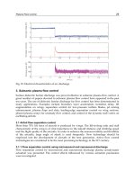
The H, D and Z components are similarly plotted for DIMAGORAS in Fig. 12.
Fig. 12. H, D and Z-Components DIMAGORAS Magnetogram.
For a distant installation, the results are transferred to the central database in an automatic
and unsupervised way. Automation software retrieves, at a specific time every day, the last
day’s data. Various methods have been tested, such as, PPP modem connection, FTP and e-
mail.
Aeronautics and Astronautics
514
5. Conclusion
The chapter presents a new reconfigurable magnetometer for measuring planetary fields.
The scale is programmable for space field measurements. The modular design allows similar
sensors’ instrumentations to be quickly evaluated. The all-digital computer architecture
implemented allows full control in both the analogue and digital domains. Almost all
hardware functions are controlled and occasionally reprogrammed by the FPGA. The FPGA
may be reconfigured approximately 20,000,000 times without any problems. 370,000 gates
are required for basic operation, which is increased to 640,000 gates for optimum results.
This great variation depends on the filters and DSP implementation. The minimum
frequency of internal operation is 60 MHz. The system acts as a pathfinder for future space
missions, since it is a replacement to existing magnetometers found in every spacecraft.
6. References
Auster, H. et al. (1995). Concept and First Results of a Digital Fluxgate Magnetometer.
Measurements Science & Technology, Vol. 7, 477-481
Chiezi, L.; Kejik, P.; Jannosy B. & Popovic R. S. (2000). CMOS Planar 2-D Microfluxgate
Sensor. Sensors and Actuators A, Vol. 82 , 174-180
Dekoulis, G. (2007). Novel Digital Systems Designs for Space Physics Instrumentation, Ph.D.
Thesis, Lancaster University
Dekoulis, G. & Honary, F. (2007). Novel Low-Power Fluxgate Sensor Using a Macroscale
Optimisation Technique for Space Physics Instrumentation. SPIE, Smart Sensors,
Actuators, and MEMS III, Vol. 6589, 65890G-1 – 65890G-8
Dekoulis, G. & Honary, F. (2008). Novel Sensor Design Methodology for Measurements of
the Complex Solar Wind – Magnetospheric - Ionospheric System. Journal of
Microsystem Technologies, Vol. 14, No. 4-5, 475-482
Dekoulis, G. & Murphy, N. (2008). New Digital Systems Designs for Validating the JPL
Scalar Helium Magnetometer for the Juno Mission. NASA JPL Research Report
Kawahito, S. et al. (1999). A Delta-Sigma Sensor Interface Technique with Third Order Noise
Shaping. Transducers Conference, Sendai, Japan, 824-827
Macmillan S.; Barraclough, D. R.; Quinn, J. M. & Coleman, R. J. (1997). The 1995 Revision of
the Joint US/UK Geomagnetic Field Models - I. Secular Variation. Journal of
Geomagnetism & Geoelectrism, Vol. 49, 229 – 243
Meydan, T. (1995). Application of Amorphous Materials to Sensors. Journal of Magnetic
Materials, Vol. 133, 525-532
Ness, N. F. (1970). Magnetometers for Space Research. Space Science Review, Vol. 11, 459-554
Pallas-Areny, R. & Webster, J. G. (1991). Sensors and Signal Conditioning. New York: Wiley
Pedersen, E. B. et al. (1999). Digital Fluxgate Magnetometer for the Astrid-2 Satellite.
Measurements Science & Technology, Vol. 10, N124-N129
Primdahl, F. et al. (1994). Digital Detection of the Fluxgate Sensor Output Signal.
Measurements Science & Technology, Vol. 5, 359-362
Seidemann, V.; Ohnmacht, M.; & Buttgenback, S. (2000). Microcoils and Microrelays- An
Optimised Multilayer Fabrication Process, Sensors and Actuators A, Vol. 83, 124-129
(2003). SAMNET Data Collection and Processing. Lancaster University Technical Report
19
Aeronautical Data Networks
Mustafa Cenk Erturk, Wilfrido Moreno, Jamal Haque and Huseyin Arslan
University of South Florida
USA
1. Introduction
The wireless connectivity is becoming an integral part of our society. The advances in signal
processing, rapid prototyping and an insatiable consumer demand for wireless connectivity
is opening a new paradigm of data service, “Aeronautical Data Networks (ADN)”.
Programs lead by National Aeronautics and Space Administration (NASA), Federal
Aviation Administration (FAA) [NASA/CR-2008], EUROCONTROL and Networking the
Sky for Civil Aeronautical Communications (NEWSKY) [Newsky] are all including the
aeronautical platform as part of their network. The objective is to provide a low delay and
cost effective data network for an aeronautical platform, as well as use it as a relay for
ground and airborne nodes [Sakhaee], [Medina]. Most of current systems use a satellite for
connecting to an aeronautical platform. Satellite resources are limited, expensive and offer
limited data throughput as compared to a terrestrial networks. Moreover, frequency
spectrum is a valuable estate and needs to be used efficiently. Hence, advance spectrum
efficient techniques needs to be evaluated for this environment.
The book chapter will explore the challenges of aeronautical environment to provide
connectivity at all times. A detail analysis with mathematical equations will be presented to
show the aeronautical channel impairments. The impact of Doppler on the channel that
limits the use of a highly efficient modulation scheme, such as orthogonal frequency
division multiplexing (OFDM), will be presented. Doppler has a major impact on OFDM
based systems. In addition, Doppler spread in ADN depicts rather different characteristics
compared to terrestrial networks, i.e., multiple Doppler shifts in the channel and profound
delays. Results of parametric spectrum estimation methods for extracting the Doppler shifts
will be presented.
OFDM in combination with dense encoding, offers a robust communication and spectrum
compression, however its usage is limited to terrestrial domain due to Doppler. OFDM
sensitivity to frequency shifts results in intercarrier interference (ICI) and degrades spectral
efficiency. High mobility platform, such as train and aircraft offer a challenging
environment for OFDM. OFDM ICI and frequency shift caused by the high mobility of the
platform is investigated and potential methods are proposed.
ADN’s can provide a critical service for various situations, such as: public safety
communications, denial of service (DoS), disaster situations, in-flight Internet, as well as
mobile communication on the ground such as providing services for highways, trains etc.
The network connectivity of ADN will be explored. Current and future prospects of ADN
will be discussed in terms of cross interoperability with a terrestrial backbone. The result of
Aeronautics and Astronautics
516
a notional network capacity analysis is presented. Connectivity and robustness of an
Aeronautical based Network, both as a relay for terrestrial networks and to provide in-flight
internet will be presented.
Finally the chapter will explore the system and architecture requirements for a cognitive
driven reconfigurable hardware for an aeronautical platform, such as commercial aircraft or
high altitude platforms. The scope of such a system would provide an intelligent
configurable radio system, provide connectivity for a changing geographical, political and
regulatory environments that an aircraft experiences. Such a system will take advantage of
opportunistic services available for today and future. With advances in components and
processing hardware, mobile platforms such as those mentioned above are ideal candidates
to have configurable hardware that can morph itself, given the location and available
wireless service. The global movement of the aeronautical system can take advantage of
emerging wireless services and standards. This section of the chapter will propose a system
for an intelligent self-configurable software and hardware solution for an aeronautical
system, Cognitive Aeronautical Software Defined Radio (CASDR).
2. Motivation and challenges
The ever-changing geographical environment of an aircraft and an increasing availability of
different wireless services make’s one wonder, what if such services can be accessed in real
time.
This provided the motivation to develop a concept system and its hardware that would
accommodate to the rapid changes, not just due to the aircraft location, but also to support
the growth of services and industry evolution. Fig. 1 depicts the notional framework of
opportunistic wireless data service that may be available for an aircraft in flight. At higher
altitude the services may be more traditional and fixed, however on ground, the growing
WiMAX and local area network services may be available to be accessed from the aircraft.
The high-speed mobility of an aircraft adds additional challenges to the design of system
physical layer, such as path loss and multi-Doppler spread.
3. Literature review
The desire for a universal and a reconfigurable terminal first appeared in the military area.
The need for mobility and accessibility was the driving requirement. One of the early
concept was a reconfigurable system appeared as an equipment called “SPEAKeasy”. The
Software Communications Architecture (SCA) developed by the Joint Tactical Radio System
(JTRS) program of the U.S. Department of Defense (DoD) further fueled the growth of SDR.
JTRS aims to provide a family of digital, programmable, multiband, multimode, modular
radios to alleviate communications interoperability problems. Finally the work of J. Mitola
[Mitola_1], there is now a growing interest in reconfigurable terminals.
The increase in air traffic is resulting in the surge of commercial airborne communication
system [Eurocontrol]. Aircell and AeroSat have developed the ground based hardware and
now offer in flight Internet service. Aircell uses a concept of air-to-ground link
[Bluemenstein] and provides the in-flight Internet service called ‘gogo’ on aircrafts. GOGO
service works of cellular phone base stations in the continental US, which act as access
points for an en route flight. A recent flight from Tampa, Florida to Detroit, Ohio USA, a
user using GOGO service experienced an average upload speed of 0.27 Mbits/s and an
Aeronautical Data Networks
517
Fig. 1. Aeronautical System
average download speed of 0.33 Mbits/s with latency of 233ms. However, the ground based
service is limited to flight coverage over land only. For the oceanic flight satellite based
connectivity is required. AeroSat developed satellite communication (SATCOM) Ku band
for commercial airliners [AeroSat]. This offers broad connectivity, however the cost and data
throughput of satellite based service is not conducive to user demand.
The growth in SDR has been enabled by advances in semiconductor, which has led to the
development of programmable multi-core General Purpose Processor (GPP), Digital Signal
Processor (DSP), Field Programmable Gate Array (FPGA) and Analog to Digital Converter
(ADC). GPP, DSPs and FPGAs provide the programmability and processing capability to
realize such a system. Hence, the processing chain starting from digital intermediate frequency
(IF) down to demodulation can be implemented in digital signal processing [Srikanteswara],
[Mohebbi]. Another key enabler is the high speed ADC that bridges the analog and digital
world [Zanikopoulos], [Salkintzis]. Advance algorithms that require intense processing can
now be implemented in the combination of these moderate size, weight and power processing
Aeronautics and Astronautics
518
engines. FPGA’s, with their ability to parallelize, can implement intense processing algorithms
that may be difficult to implement in a DSP or GPP.
Therefore the maturity of; SDR algorithm’s, high bandwidth processing engines, development
of tunable antenna and availability of high speed ADC makes the implementation of CASDR a
possibility. The global mobility of an Aeronautical platform is the ideal implementation of a
CASDR concept. A CASDR will learn and configure itself in order to provide multi
standard/service modem’s as it traverses continents, countries and cities.
4. Aeronautical system
4.1 ASDR system scope
The scope of this system would be to provide an intelligent configurable radio system,
provide connectivity for a changing geographical, political and regulatory environments
that an aircraft experiences. Such a system will take advantage of opportunistic services
available today and planned in future.
The communication design is beginning to converge on standard building blocks, or
systems, which form the basic building block of a communication system, i.e., Read
Solomon, Turbo Encoder, Modulations, Viterbi etc. Whether a communication link is being
developed for short range, long range, line of sight (LOS) or non line of sight (NLOS) the
basic building blocks of communication system are the same. If available in software they
can be stitched together to build a radio transceiver. Aeronautical Networks (ANs) could be
an important application of such systems, since different regions or countries assign
different frequency bands based on their needs and spectrum allocation policies.
4.2 Aeronautical network geometry
Geometric relations are observed between an aircraft station (AS) or an aircraft’s altitude
(h1) with a Ground Station (GS). The LOS communication distance (without considering
Fresnel and other parameters) from AS to GS can be calculated using the Pythagoras
theorem as follows:
5.0
1
5.0
111
22 RhhRhd
(1)
where, R is the radius of the Earth which varies from 6336 km to 6399 km, but assumed 6370
km (for the purpose of calculations). For distances between the two nodes above the sea
level, the above formula needs additional steps for calculating the communication distance.
The formula is calibrated by a statistically measured parameter by International
Telecommunication Union (ITU), i.e., ‘k’.
5.0
11
2Rkhd
(2)
Figure 2 shows the maximum communication distances that can be achieved between AS
and AS/GS. The jump in the first 2 km altitudes for GS communications can be considered a
very low orbit AS which can reach a communication zone of D=120 km. Many commercial
planes flying at the altitude of 9 km can potentially create communication zones about
D=250 km with a very conservative approach (k=0.5). On the other hand, considering the
communication distance between two ASs, it can be inferred that it could reach up to
D=480 km with k=1/2.
Aeronautical Data Networks
519
Fig. 2. Communication zone of an AS
Figure 2 shows that ASs could be used as a backhaul or relay for wireless infrastructures,
since they have the capability of communicating long distances as compared to wireless
ground backhauls. Aeronautical Network (AN) will have a substantial lower round trip
delay, which will allow for a low delay telephone and voice over IP services.
4.3 Aeronautical network scenarios and data access
Aeronautical Networks can provide critical services for various situations, such as; public
safety communications, Denial of Service (DoS), disaster situations, in-flight Internet, as well
as mobile communication on the ground, providing services for highways, trains, etc. The
network structure that is being proposed in this paper is as follows: Given a particular
region to be covered, initially Service Gateway Ground Stations (SGGS) should be built
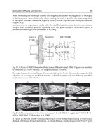
according to the communication distance, see Fig. 3. Assuming that a GS can communicate
to an AS within the distance of 200 km, roughly 8 SGGS will be able to provide service for
an area of 1600 km by 800 km.
Data access in an AN can be defined as follows: When a GS or AS has data to send, the flow
of the data should be from/to SGGS so the connection with other networks such as public
switched telephone network (PSTN), cellular networks and Internet Protocol (IP) could be
established.
To provide in-flight services, a centralized configured network should be considered; SGGSs
act like Base Stations (BS), covering a particular region where Subscriber Stations (SS) are
simply ASs. Scheduling is done by the SGGS and in this structure, AS’s are not
communicating with each other, except with SSGS’s. However, if an AS is not able to
register to a SGGS, which could be a case of oceanic flights, then data of that particular AS
should be routed to an AS which was already registered to a SGGS with ad-hoc networking
strategies.
Aeronautics and Astronautics
520
Fig. 3. Aeronautical Network Scenarios
For an AN network the use of AS as a base station used for cellular network is also
discussed. In this case, SS’s are the GS’s, which can be fixed or mobile. When a GS has data
to send, it sends its data to an AS. This can be considered as a relay, reflecting the data to its
associated SGGS to finalize the establishment. This structure is feasible to provide public
safety services in disaster scenarios, provide backhaul option for terrestrial networks and
military communication applications. Moreover, in this structure, since both AS’s and GS’s
are not fixed, the handover of a GS between multiple AS is also another challenging issue. It
is important to note that the handover process in this structure is somehow different, since
GS are doing handovers not only because of their own mobility, but also due to mobility of
AS’s.
One of the main issues in AN’s is the topology estimation. Since there are many mobile
stations, in terms of GS and AS, the scheduling and routing of data would differentiate from
time to time. In these cases the topology estimation of the network should be done properly,
so that the data can be routed and scheduled in mesh and centralized networks strategies
respectively.
4.4 Physical layer
In a wireless system design, understanding the limits and bounds of a channel impairments
theoretically and empirically are critical to the design of the system. An aeronautical
environment poses a daunting task to cover a huge area for any system designer. Global
channel characteristics need to be understood to establish model parameters. However, this
would lean toward statistical average and will result in inefficient system parameters.
Current system based on ‘gogo’ service, uses a ground based link and provides a limited
data rates. A data connectivity sample was taken for a Delta flight traversed between
Tampa, Florida to Detroit, Ohio USA, using ‘Speed Test’ (www.speedtest.net). Different
Aeronautical Data Networks
521
global servers were pinged periodically duration the flight to measure download, upload
and latency. Fig. 4 and Fig. 5 are the global data rates and latency experienced during the
flight.
Fig. 4. Global In-Flight Data Rates
Fig. 5. Global In-Flight Latency
Most of the current system, assumes a line of sight (LOS). This is also the case for the
aeronautical platforms connectivity modeling. However, an intelligent CASDR will allow
Aeronautics and Astronautics
522
for the ability to configure the system and learn the channel condition over the flight route
and establish history, hence establish accurate channel parameters for a given location,
altitude and speed. Since the aircraft traverses pre-planned route, over time this channel
parameters will provide accurate characteristics [Bello]. This will allow higher order
spectral efficient modulations and multi-carrier system to be used and provide higher
data throughput. Details of this cognitive channel sensing behavior are discussed in
section 4.
A time varying wireless impulse response is represented by equation (3), where the signal
is impaired by amplitude, phase, Doppler and time delay.
22
1
() exp exp ( )
d
kk
jjfn
hn a t
NN
N
(3)
where
k
a ,
,
d
f
and
k
are amplitude, phase, Doppler shift and delay for each path
respectively.
For a LOS, the effect of number of paths is significantly less, τ ≈ 0, f
d
, Doppler shift based on
platform would be fixed and a limited variation of phase will lead mostly to amplitude
degradation due to path loss. For the diffused path, according to Bello [Bello], it represents a
wide-sense stationary uncorrelated (WSSUS) channel, which emulates a small area
characterization for multipath channel. The effect of Doppler to the line of sight is mostly
frequency shift; however the diffused and specular reflections will have a spread due to
Doppler. This Doppler spread for an aeronautical communications depicts a bandwidth less
than 360
o
[Hoeher], [Haas], [Elnoubi]. Most of the current research assumes a two-ray model
as the channel model for flat surface areas. In an extremely mountainous terrain
environment, the channel model results in an intermittent loss of LOS along with increasing
angle spread that could match the Jakes Doppler spread. In the two limiting cases; the
angular spread at the receiver depicts either a two ray model or Jakes spectrum. Therefore, a
modified Doppler spread model needs to be developed, that will go from a narrow beam
width to 360
o
, as the mobile moves from flat to rough environments. Hence, the use of D
f
factor from 0 to 1 for the growing Doppler spread, due to beam width, represents going
from flat to rough terrain environment:
2
HL
f
D
, where
()2
HL
(4)
2,
,
f
HL
D
D
else
, where
1
cos
d
f
v
,
maxdd
ff
(5)
Doppler density going from non-isotropic to isotropic:
max
2
max
max
1
1( )
()
0
dd
d
d
fd d
d
if f f
f
Df
pf
f
else
(6)
Aeronautical Data Networks
523
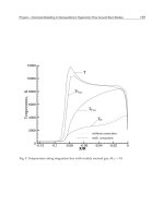
Fig. 6. Doppler Power Spectrums for ADNs
Fig. 6 shows the Air to Ground (A/G) and Ground to Air (G/A) aeronautical communications
in an en-route scenario and their corresponding Doppler spectrum. The arrival/take-off, taxi
and parking scenarios depicts different multipath and received angle spreads [Haas].The
spectrum in an en-route scenario depicts a Doppler shift with a narrow beam Doppler spread,
where it can be assumed as another Doppler shift. Among carrier and modulation systems,
orthogonal frequency division multiplexing (OFDM) is the most sensitive to Doppler. OFDM
based systems has been adopted/proposed for several current/future communication systems
all over the world, i.e., asymmetric digital subscriber line (ADSL) services, IEEE 802.11a/g/n,
IEEE 802.16, IEEE 802.20, digital audio broadcast (DAB), digital terrestrial television broadcast
(DVD) in Europe, ISDB in Japan and fourth generation (4G) cellular systems. Therefore, it is
reasonable to assume that any SDR application will also need to support OFDM in the ADN
network. In an OFDM based systems, a serial symbol stream is converted into parallel streams
and each symbol is modulated with different orthogonal sub-carriers. With the usage of cyclic
prefix (CP), since OFDM based systems have already relatively longer symbol durations
compared to single carrier systems, they are known for their robustness against frequency
selectivity of the channel, i.e., delay spread. However, longer symbol durations lead to
weakness of the OFDM systems to time variation of the channel, i.e., Doppler shift/spread
which is a challenging issue in ADN.
The two Doppler shifts affecting the system can be described as follows:
() () () ()
y
nxnhnwn
(7)
where,
()wn is noise and ()hn is the channel impulse response defined as:
2
1
2( )
() exp ( )
ii
ii
i
jfn
hn a n
N
(8)
where
i
a is the attenuation value, N is the number of FFT bins,
i
and
i
f
are the delay and
the normalized Doppler frequency shift (NDF) for the first and second ray respectively
where
Di
i
f
f
f
.
-f
dmax
f
dmax
Θ
H1
- θ
L1
θ
Los
Θ
H2
- θ
L2
θ
Los
Air to Ground
-f
dmax
f
dmax
Ground to Air
Aeronautics and Astronautics
524
For the ADN, Figure 4 presents the two-path channel model. In OFDM, as long as the
carrier’s orthogonality is maintained, then there is no bleeding of energy. Intercarrier
interference (ICI) is related to sub-carrier bandwidth and their proportional interference
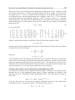
due to Doppler offset. As an example, an estimation of ICI interference for a system with
64 point FFT OFDM symbol, which has a 312 kHz subcarrier bandwidth, is plotted in
Fig. 7.
The Fig. 7 shows the ICI error vector contribution due to frequency shift caused by Doppler
in a two ray model. At 0.1 fraction of sub carrier frequency the ICI error contribution
approaches -10dB. To support higher spectral efficiency generally ICI should remain within
or less than 0.02 fraction of sub-carrier frequency. This will allow ICI interfering energy to
remain well below -25 dB allowing higher spectral efficiency.
0 0.02 0.04 0.06 0.08 0.1 0.12 0.14 0.16
-50
-45
-40
-35
-30
-25
-20
-15
-10
-5
Freqency offset/subcarrier spacing
Error, dB
Error Magnitude with Frequency Offset
Theory One Doppler
Theory Two Doppler
Simulation Two Doppler
Fig. 7. Doppler ICI vs. Sub-carrier BW
4.5 Cognitive route based physical layer estimates
The aircraft routes driven by FAA for various segments are ideal to establish a history of
wireless channel conditions for the route. Once a route is traversed, its history of channel
impairments are stored with associated coordinates and aircraft attitude information. This
data is downloaded to a central database to be shared with another aircraft. For new routes,
the cognitive channel estimator will try to understand the channel condition. Over time, the
channel history collected from different aircraft will create a channel map for each route.
The ASDR will then be able to download this data and prior to a flight adjust the physical
layer parameters for the route. For a mobile platform that has a predetermined route, such
as AN, the channel estimation is broken down to static and dynamic components. The static
components effecting the channel would be large objects i.e., mountains, buildings, etc. The
averaging over multiple routes will provide of stable static channel estimates. The dynamic
components will be due to time varying objects.
Aeronautical Data Networks
525
5. Aeronautical software define radio
The advances in components and signal processing techniques are the leading enabler for a
configurable hardware and intelligent software. Software defined radio emerges from the
desire of single radio hardware that molds its feature to different radio schemes [Apostolis].
The artificial intelligence needed for the smarts of such configurable hardware is emerging
into what is known as cognitive radio [Mitola_2].
Fig. 8. Route based Channel Sensing
Cognitive algorithms combined with configurable hardware can take full advantage of
varying location of an aircraft, whether that is in the air, en route and lends themselves to
take advantage of opportunistic spectrum and network connectivity.
A system with the ability to morph to accommodate the aeronautical changing
environments, channels conditions across domestics and international boundaries is
required. Aeronautical software defined radio (ASDR) platform will also allow the
flexibility to comply with countries regulations governing the spectrum usage and
interference.
5.1 Spectrum coverage
The spectrum bandwidth use and frequency band allocation for different systems is one of
the challenges to overcome for truly building an ASDR capable of accommodating itself for
different regions. For a given region or country, the standard may be the same but the
frequency band used may be different. For example, the 802.16 specification applies across a
wide range of radio frequency spectrum and WiMAX could function on any various
frequencies i.e., 2.5 GHz is predominantly being used in the USA, elsewhere in the world 2.3
GHz used in Asia and some countries are using 3.5 GHz.
The Analog TV bands (700 MHz) may become available for WiMAX usage, but currently it
is being used for digital TV, however different countries might choose to use the spectrum
that best suits their needs. Table 1 below lists opportunistic frequency data network
available [Zhang], [Peter].
Aeronautics and Astronautics
526
Band
(GHz)
BW (MHz) Standard Region Service
2.4 20 802.11b/g US Wi-Fi
5 20 802.11a US Wi-Fi
2.5 20 802.16 US Fixed WiMAX
3.5,2.5 20 802.16a Can Fixed WiMAX
2.3 20 802.16e Aus Fixed WiMAX
1.616 -
1.6265
10.5 Custom Global
Iridium Down
Link
19.4 -19.6 20 Custom Global Iridium Up Link
2,4 Sirius/XM US QPSK, OFDM
1.9, 0.85 1.23, 5 W/CDMA US 3G Cellular
1.8, 0.9 1.23, 5 W/CDMA EU 3G Cellular
0.5 – 0.8 n/a n/a Analog TV
Table 1. Wireless Standards
Another feature that will be necessary in a SDR application is a tunable RF front end capable
of locking on the various bands.
Frequency bands and bandwidths for future wireless communication studies in terms of
aeronautical communications are discussed at the World Radio communication
Conference (WRC) 2007. This international body maintains and agrees to abide by the use
of spectrum by international treaty. Aeronautical Mobile (Route) Service (AM(R)S)
communication is defined as a safety system requiring high reliability and rapid response.
Safety and security applications together with, Air Traffic Control (ATC) and Air Traffic
Management (ATM) communications are considered to be AM(R)S. To accommodate the
future growth of aeronautical communication, new band allocations are being made in
AM(R)S rather than VHF band in L and C. L band (960-1164 MHz) and C band (5091-5150
MHz) allocations are discussed in the meeting. L band is suggested as a suitable band for
future aeronautical communication studies. C band is considered to be used in Airport
surface network systems, since it is thought to be useful for short range, high data
throughput.
5.2 Critical system parameters
Cognitive radio system will require optimization of system performance. Algorithms
capable of real time optimizing the system performance as well as pre/post flight will create
pre-flight configuration Table 2;
Aeronautical Data Networks
527
Aeronautical Optimization Parameters
Customer Usage
DQ: Quantity of data transferred at various flight segments.
DT: Duration of data transfer per segmented route.
TC: Traffic classes: multi-media, navigation, system health & safety.
BER: Required Bit error rate per Traffic Classes.
Network & Data Access Layer
Protocol Selection, Routing configuration, Forward error selection given the customer
driven BER, Available to provide relay service, Packet error rate
Physical Layer
T
M
:Multipath delay spread: Characterizes channel smearing due to arrival of multi-
signal reflection arrivals.
f
DS:
Doppler spread or Doppler bandwidth.
f
d:
Doppler Shift.
Α: Attenuation: power loss, function of frequency and distance.
L: Impulse Response Length: length, in signal elements, of CIR.
Band: Carrier frequency Band.
BW: Available bandwidth.
SWP: Standard waveform performance.
Table 2. Parameters
5.3 Aeronautical cognitive radio
The term cognitive comes from psychology meaning “brains” the ability to learn and
understand. The aeronautical environment is ideal application for an intelligent radio,
Fig. 9. Aeronautical SDR and CE
Aeronautics and Astronautics
528
which is capable of learning the environment for various locations and altitudes, see Figure
7 and 8. Over time, each aircraft flying over certain route will store the data on board
storage devices. This data shall contain the route the airline/aircraft traversed, the
opportunist wireless links available, frequency band, bandwidth, data rate, wireless
standard, signal quality for the route, etc. Upon arrival at the destination, data is then
downloaded to a centralized flight communication data bank. This data is then available for
flights heading on the same route.
5.4 Aeronautical cognitive intellegence
The brain of the aeronautical cognitive engine would be to work of its constant awareness of
aircraft geographical location and RF channel. It will sense weather conditions that may
affect the radio transmission and available services available.
Fig. 10. Cognitive Engine
Awareness:
The aircraft navigation and radar systems will provide the sensing stimulation to the
cognitive engine. The inertial measurement unit (IMU) used for flight navigation will
provide aircraft speed, altitude, and attitude. Advance forward looking radar will provide
the weather conditions that may affect the radio transmission performance. Global
position system (GPS) will provide location of the aircraft with respect to global
geography. Furthermore, the awareness engine will have the ability to estimate the data
requirements based on past data use and flight profile, before accessing the spectrum for
services.
Learn:
The cognitive awareness provides an opportunity for CASDR to learn the spectrum usage,
data demand and system throughput based flight route during day or night. Such statistics
will allow a constant learning and developing statistics profile that is stored for each route.
This allows cognitive radio of other airlines that have not travelled that particular route to
have a priori knowledge and schedule services accordingly. The system parameters
available at particular location can be configured for that country or location.
Aeronautical Data Networks
529
The channel sensing and estimation for the flight route will serve to establish channel
statistics, as shown in Fig. 11. Aeronautical Channel Sensing. The CASDR cognitive channel
awareness can configure the system to establish channel impairments for the flight route.
Fig. 11. Aeronautical Channel Sensing
Remember:
System performance data gathered for different flight routes through different airlines will
serve as means to remember these flight parameters, exchanged through a centralized data
archives. Such data will grow in time and averaging over time will provide a reliable
statistics for configuring the SDR radio parameters.
Adapt and Predict:
The cognitive engine learning and sensing ability with an aircraft system will allow ability
to predict system configuration parameters and adapt them to data gathered through flights
travelled by other carriers.
5.5 Aeronautical configurable hardware
The key to a configurable system for an aeronautical system is to design hardware with
minimum analog front-end, access different antenna system, digitize the signal and a
scalable architecture. Fig. 12. Aeronautical Software Defined Radio presents such a system.
The RF front-end board will support multiple bands with varying gain amplifiers. Closely
coupled A/D boards with FPGAs are required for high-speed data connectivity and
processing. A technique such as under sampling for demodulations is used to reduce the
front-end components. The advances in ADC devices as well as non-compliance feature of
Nyquist sampling theory is an enabler for an ASDR application. Violation of Nyquist theory
will create signals aliased at integer multiple of sampling frequency (N* fs). This put the
Aeronautics and Astronautics
530
challenge on front-end processing system. The advances in programmable Digital Signal
Processing (DSP) and Field Programmable Gate Array (FPGA) are ideal for such processing
[Susaki]. FPGA offers ability to parallelize processing hence, allow a high-end processing
throughput. The Virtex-6 FPGA family by Xilinx provides up to 2,016 DSP48 slices that
deliver up to 1000 Giga MAC/s of DSP processing performance. Xilinx offers solutions for
evolving standards such as WCDMA, WiMAX, TD_SCDMA and LTE. Texas instrument
DSP products are now offering six DSP processors in a single package with processing
capability 4000 million MACS (16-Bits) at 500 MHz.
Fig. 12. Aeronautical Software Defined Radio
6. Conclusions
The advances in component technology, evolution in communication services, and increase
in data demand and aircraft mobility creates an ideal application for CASDR to support the
aeronautical system. Current deployed systems are beginning to form shape, i.e., gogo,
however they are now adding another hardware box to provide connectivity. Since the
system is hardwired for a particular modem, the evolution will require hardware
modification to keep up with growth in the telecommunication growth. Accurate
measurements of channel characteristics, such as Doppler, will allow spectral efficient
modulation to be used for higher data rates. Advance algorithms along with processing
capabilities can resolve the impact Doppler, due to aircraft high mobility. The novel
cognitive channel measurement and estimation for each route will increase spectrum
efficiency and in return provide high data throughput. An optimum combination of
bandwidth, subcarrier bandwidth, acceptable Doppler frequency and multipath immunity
system can be developed for ADN. This will result in an efficient use of the spectrum and
provide a high data rate for the global connectivity.
7. References
AeroSat Corporation. (2008). About Airborne SatCom [Online]. Available:
www.aerosat.com/about/ about_airborne_satcom.asp
Apostolis K. S., Hong N., & P. Takis Mathiopoulos, ADC and DSP Challenges in the
Development of Software Radio Base Stations.
Bello P. A., “Aeronautical channel characterization,” IEEE Trans. communication., vol. COM-
21, pp. 548–563, May 1973.
Aeronautical Data Networks
531
Blumenstein J. (2007). Aircell: Inflight Wi-Fi Built for the Airline Business [Online].
Available: blog.aircell.com.
Elnoubi, S.M., "A simplified stochastic model for the aeronautical mobile radio channel,"
Vehicular Technology Conference, 1992, IEEE 42nd , vol., no., pp.960-963 vol.2, 10-13
May 1992.
Eurocontrol, STATFOR - Air Traffic Statistics and Forecasts,
Haas, E., "Aeronautical channel modeling," Vehicular Technology, IEEE Transactions on, vol.51,
no.2, pp.254-264, Mar 2002.
Hoeher, P., & Haas, E., "Aeronautical channel modeling at VHF-band," Vehicular
Technology Conference, 1999. VTC 1999 - Fall. IEEE VTS 50th, no., pp.1961-1966
vol.4, 1999.
Medina D., F. Hoffman, Ayaz, S., Rokitansky, C. H., Feasibilty of an Aeronautical
Mobile Ad-Hoc Network Over the North Atlantic Corridor, Proceedings of IEEE
Secon 2008.
Mohebbi B., E. C. Filho, R. Maestre, M. Davies, & F. J. Kurdahi, “A case study of mapping a
software-defined radio (SDR) application on a reconfigurable DSP core,” in
Proceedings of 1st IEEE/ACM/IFIP International Conference on Hardware/Software
Codesign and System Synthesis, pp. 103–108,Newport Beach, Calif, USA, October
2003.
Mitola_1 J. and Gerald Q. Maguire, Jr, Cognitive Radio:Making Software Radios More
Personal.
Mitola_2 J., The software Radio architecture, IEEE Commun. Mag, vol. 33, no. 5, pp. 26 38,
May 1995.
NASA/CR—2008-215144, Future Aeronautical Communication Infrastructure Technology
Investigation.
Newsky Project website:
Peter W., Glenister, S M., & Alan W. Miller Motorola IEEE AES Systems Magazine, November
1999.
Salkintzis, A.K., Hong Nie, & Mathiopoulos, P.T., “ADC and DSP challenges in the
development of software radio base stations,” IEEE Personal Communications, vol. 6,
no. 4, pp. 47–55, Aug. 1999.
Sakhaee, E., & Jamalipour, A., "The Global In-Flight Inter-net," Selected Areas in
Communications, IEEE Journal on , vol.24, no.9, pp.1748-1757, Sept. 2006.
Srikanteswara R., Chembil Palat, R., Reed J. H., & Athanas P., An Overview of Configurable
Computing Machines for Software Radio Handsets, IEEE comms Mag., Vol.41 No.7,
pp.134-141, July 2003.
Susaki H., “A Fast Algorithm for High-Accuracy Frequency Measurement: Application to
Ultrasonic Doppler Sonar,” in IEEE journal of oceanic engineering, vol. 27, no. 1,
January 2002.
Zhang, Y., & Nirwan Ansari, Wireless Telemedicine service over integrated
IEEE802.11/Wlan and 802.16/Wimax, IEEE Wireless Communications, February
2010.
Aeronautics and Astronautics
532
Zanikopoulos A. Hegt, & Van Roermund H., A. Programmable/Reconfigurable ADCs For
Multi-standard Wireless Terminals, IEEE Conferences in Communications, Circuits and
Systems Proceedings, 2006 International Conference, Volume: 2, 2006 , Page(s): 1337
– 1341.
20
Air Traffic Control Decision Support for
Integrated Community Noise Management
Sander J. Hebly
1
and Hendrikus G. Visser
2
1
National Aerospace Laboratory
2
Delft University of Technology
The Netherlands
1. Introduction
The noise resulting from flight operations at major airports is a continuing source of
annoyance in nearby residential communities. This being recognized by the industry, new
aircraft generations continue to be less noisy than their predecessors, but this development
in itself does not solve the problem in a fast growing market. Therefore a range of mitigation
measures has been implemented at airports located close to sensitive communities. Some of
these measures, like (night) curfews, restrictions on flight numbers and noise pricing tend to
control and/or shape the demand from the airport’s point of view. A second range of
measures, including the use of noise preferential runways, noise abatement routes and the
use of low noise procedures aims at a reduction of noise impact without interfering with the
supply of airport capacity or the demand for air traffic.
The implementation of noise abatement procedures at the side of Air Traffic Control (ATC)
authorities is not always straight forward, as it may interfere with respect to safety and
efficiency requirements. This can be observed when considering the current implementation
of the Continuous Descent Approach (CDA). The trade-off for this procedure is either to
accept a less than ideal continuous descent, or to accept a reduced arrival capacity (Davison
Reynolds et al., 2006; Kershaw et al., 2000; Weitz et al., 2005). However, contradictory
requirements are not the only problem that air traffic controllers face with respect to
reducing community noise impact. Taking noise beneficial decisions can also be difficult
because of a lack of noise-related information. Usually, controllers have access to ‘static’
information, like the preferred use of certain routes and runways. However, they are not
provided with information on the continuously developing situation with respect to
community noise exposure. This means for example that they cannot respond to
developments in the noise exposure in the past or expected developments in the near future.
Nor can they evaluate the environmental effects of a tactical or operational decision they are
about to take.
This paper presents a concept for integrated community noise management in the form of a
decision support system (DSS) for air traffic controllers. It should assist controllers in
guiding arriving and departing traffic near airports in a safe and efficient matter, making
use of the future concept of four-dimensional trajectory-based operations and future
technology currently under development. The system should be able to create conflict-free