Electric Vehicles Modelling and Simulations Part 6 pptx
Bạn đang xem bản rút gọn của tài liệu. Xem và tải ngay bản đầy đủ của tài liệu tại đây (1.27 MB, 30 trang )
Vehicle Stability Enhancement Control for Electric Vehicle Using Behaviour Model Control
139
Fig. 17. Control structure deduced from the inversion
Fig. 18. Inversion of the converter CR: (a) COG; (b) EMR
3.5 Anti skid strategy by BMC
3.5.1 The BMC structure
The behaviour model control (BMC) can be an alternative to other robust control strategies.
It is based on a supplementary input of the process to make it follow the model (Hautier,
1997 ; Vulturescu, 2000; Pierquin, 2000).
The process block correspondens to the real plant, Fig. 19. It can be characterised by its input
vector
u and its output vector y.
The control block has to define an appropriated control variable
u, in order to obtain the
desired reference vector
y
ref
.
The model block is a process simulation. This block can be a simplified model of the process.
The difference between the process output
y and the model output y
mod
is taken into account
by the adaptation block. The output of this block acts directly on the process by a
supplementary input, Fig. 19. The adaptation mechanism can be a simple gain or a classical
controller (Vulturescu, 2004).
Motor
control 1
C-TM1
ref
v
1
refm
1refm
T
1
v
r
F
v
MS
2t
F
1t
F
1rm
T
1m
1
v
1m
v
1m
T
1t
F
EM1
CR1 TM1
reft
F
1
ref
v
1
reft
F
1
1t
F
1
v
v
1t
F
CR1
(b)
1t
F
reft
F
1
1
v
1t
F
v
f
ref
v
1
ref1
(a)
Electric Vehicles – Modelling and Simulations
140
Fig. 19. Example of a BMC structure
3.5.2 Application of the BMC control to the traction system
The first step to be made is to establish a behaviour model. In this case, we choose a
mechanical model without slip, which will be equivalent to the contact wheel-road in the
areas known as pseudo-slip. This model can be considered as an ideal model. However, the
inertia moments of the elements in rotation and the vehicle mass can be represented by the
total inertia moments
J
t_mod
of each shaft motor which is given by:
2
~
~~~
_modt
red
J
J
Mkr
(23)
The dynamic equation of the model is given by:
mod
_mod _mod _modtmrm
d
JTT
dt
(24)
By taking into account the wheel slip, the total inertia moments will become:
2
1
t red
JJ M kr
(25)
We now apply the BMC structure for one wheel to solve the skid phenomenon described
before. In Fig. 20, we have as an input the reference torque and as an output the speed of the
motor which drives the wheel. However, the main goal of this structure of control is to force
the speed
m
of the process to track the speed
m_mod
of the model by using a behaviour
controller.
It was shown that the state variables of each accumulator are not affected with the same
manner by the skid phenomenon. The speed wheel is more sensitive to this phenomenon
than that of vehicle in a homogeneous ratio to the kinetic energies, Fig. 5(a). Hence, the
motor speed is taken as the output variable of the model used in the BMC control. The
proposed control structure is given by Fig. 20.
Vehicle Stability Enhancement Control for Electric Vehicle Using Behaviour Model Control
141
Fig. 20. BMC control applied to one wheel
The influence of the disturbance on the wheel speeds in both controls is shown in Fig. 21. An
error is used to compare the transient performances of the MCS and the BMC. This figure
shows clearly that the perturbation effect is negligible in the case of BMC control and
demonstrates again the robustness of this new control.
Fig. 21. Effect of a loss of adherence of MCS and BMC controls
Electric Vehicles – Modelling and Simulations
142
4. Simulation results
We have simulated by using different blocks of Matlab/Simulink the proposed traction
system. This system is controlled by the behaviour model control (BMC) based on the DTC
strategy applied to each motor, Fig. 20, for the various conditions of environment (skid
phenomenon), Fig. 22.
Fig. 22. BMC structure applied to the traction system
Vehicle Stability Enhancement Control for Electric Vehicle Using Behaviour Model Control
143
Case 1 Case 2
Case 3 Case 4
Fig. 23. Simulation cases. Dry road Slippery road
4.1 Case 1
Initially, we suppose that the two wheels are not skidding and are not disturbed. Then, a
80
km/h step speed is applied to our system. We notice that the speeds of both wheels and
vehicle are almost identical. These speeds are illustrated in the Fig. 24(a) and (b). Fig. 24(c)
shows that the two motor speeds have the same behaviour to its model. The difference
between these speeds is represented in the Fig. 24(d). From Fig. 24(e) we notice that the slips
1
and
2
of both wheels respectively, are maintained in the adhesive region and the traction
forces which are illustrated by the Fig. 24(f) are identical, due to the same conditions taken
of both contact wheel-road. The motor torques are represented in Fig. 24(g) and the imposed
torques of the main controller and the behaviour controllers are shown in Fig. 24(h). The
resistive force of the vehicle is shown by the Fig. 24(i).
4.2 Case 2
We simulate now the system by using the BMC control and then applying a skid
phenomenon at 10
ts
to wheel 1 which is driven by motor 1 when the vehicle is moving at
a speed of
80 /km h . The skidding occurs when moving from a dry road (
1
()) to a
slippery road (
2
()) which leads to a loss of adherence.
The BMC control has a great effect on the adaptation blocks and by using the behaviour
controllers to maintain permanently the speed of the vehicle and those of the wheels close to
their profiles, Fig. 25(a). However, both driving wheel speeds give similar responses as
shown in Fig. 25(b).
Figure 25(c) shows that the two motor speeds have the same behaviour with the model
during the loss of adherence. The difference between these speeds which is negligible is
represented in the Fig. 25(d).
Electric Vehicles – Modelling and Simulations
144
The loss of adherence imposed on wheel 1 results to a reduction in the load torque applied
to this wheel, consequently its speed increases during the transient time which induces a
small variation of the slip on wheel 2, Fig. 25(e). The effect of this variation, leads to a
temporary increase in the traction force, Fig. 18(i). However, the BMC control establishes a
self-regulation by reducing the electromagnetic torque
1m
T of motor 1 and at the same time
increases the electromagnetic torque
2m
T to compensate the load torque of motor 2, Fig. 25(j)
and Fig. 25(k). Figures 25(n) and 25(o) show the phase currents of motor 1 and motor 2
respectively.
4.3 Case 3
In this case, the simulation is carried out by applying a skid phenomenon between
10ts
and 16ts only to wheel 1.
As shown in Fig. 26(i). and during the loss of adherence, the traction forces applied to both
driving wheels have different values. At 16ts
, when moving from a slippery road (
2
())
to a dry road (
1
()
), the BMC control establishes a self-regulation by increasing the
electromagnetic torque
1m
T of motor 1 and at the same time decreases the electromagnetic
torque
2m
T of motor 2, Fig. 26(j) and (k) which results to a negligible drop of speeds, Fig.
26(d), (e) and (f).
4.4 Case 4
The simulation is carried out by applying a skid phenomenon to both wheels successively at
different times. Figure 27(c) shows that the two motor speeds have the same behaviour to
the model. The difference between these speeds is represented in the Fig. 27(g).
When the adherence of the wheel decreases, the slip increases which results to a reduction
in the load torque applied to this wheel. However, the BMC control reduces significantly
the speed errors which permits the re-adhesion of the skidding wheel. Therefore, it is
confirmed that the anti-skid control could maintain the slip ratio around its optimal value,
Fig. 27(h).
(a) (b)
Vehicle Stability Enhancement Control for Electric Vehicle Using Behaviour Model Control
145
(c) (d)
(e) (f)
(g) (h)
Electric Vehicles – Modelling and Simulations
146
(i) (j)
(k) (l)
Fig. 24. Simulation results for case 1
(a) (b)
Vehicle Stability Enhancement Control for Electric Vehicle Using Behaviour Model Control
147
(c) (d)
(e) (f)
(g) (h)
Electric Vehicles – Modelling and Simulations
148
(i) (j)
(k) (l)
(m) (n)
Vehicle Stability Enhancement Control for Electric Vehicle Using Behaviour Model Control
149
(o)
Fig. 25. Simulation results for case 2
(a) (b)
(c) (d)
Electric Vehicles – Modelling and Simulations
150
(e) (f)
(g) (h)
(i) (j)
Vehicle Stability Enhancement Control for Electric Vehicle Using Behaviour Model Control
151
(k) (l)
(m) (n)
(o)
Fig. 26. Simulation results for case 3
Electric Vehicles – Modelling and Simulations
152
(a) (b)
(c) (d)
(e) (f)
Vehicle Stability Enhancement Control for Electric Vehicle Using Behaviour Model Control
153
(g) (h)
(i) (j)
(k) (l)
Electric Vehicles – Modelling and Simulations
154
(m) (n)
(o)
Fig. 27. Simulation results for case 4
5. Conclusion
In this chapter, a new anti-skid control for electric vehicle is proposed and discussed. This
work contributes to the improvement of the electric vehicle stability using behaviour model
control. According to the results obtained by simulations for all the cases, the proposed
traction system shows a very stable behaviour of the electric vehicle during the various
conditions of adherence.
6. Abbreviations
COG : Causal Ordering Graph
DTFC : Direct Torque Fuzzy Control
EC : Electrical Coupling
EM : Electrical machine
Vehicle Stability Enhancement Control for Electric Vehicle Using Behaviour Model Control
155
EMR : Energetic Macroscopic Representation
ES : Electrical Source
EV : Electric Vehicle
MC : Mechanical Coupling
MCS : Maximum Control Structure
MMS : Multi-machine Multi-converter Systems
MS : Mechanical Source
PMSM : Permanent Magnet synchronous Machine
SC : Static converter
7. Appendix
Parameter Symbol Unit Value
Vehicle total mass
M
Kg 1200
Wheel radius
r
m 0,26
Aerodynamic drag coefficient
C
D
N/(ms)2 0,25
Vehicle frontal area
S
m² 1,9
Gearbox ratio
k
red
– 1/7,2
Efficiency of the gearbox
– 0,98
Table 3. The Specifications of the Vehicle Used in Simulation
Parameter Symbol Unit Value
Resistance
R
0,03
d -axis inductance
d
L
H
2.10
-4
q
-axis inductance
q
L
H
2.10
-4
Permanent magnet flux
f
Wb 0,08
Pole pairs
p
–
4
Table 4. The specifications of motors
Electric Vehicles – Modelling and Simulations
156
8. References
Bouscayrol, A.; Davat, B.; de Fornel, B.; François, B.; Hautier, J.P.; Meibody-Tabar, F.;
Monmasson, E.; Pietrzak-David, M.; Razik, H.; Semail, E.; Benkhoris, F. (2003),
Control structures for multi-machine multi-converter systems with upstream
coupling. Elsevier, Mathematics and computers in simulation Vol. 63, pp. 261-270,
2003.
Bouscayrol, A.; Davat, B.; de Fornel, B.; François, B.; Hautier, J.P.; Meibody-Tabar, F.;
Pietrzak-David, M. (2000), Multi-machine multi-converter systems for drives:
analysis of couplings by a global modelling. in: Proceedings of the IEEE-IAS Annual
Meeting, Rome, October 2000.
Arnet, B.; Jufer, M. (1997), Torque control on Electric vehicles with separate wheel drives.
Proceeding of EPE'97, Trondhein, Vol. 4, pp. 39-40, 1997.
Hartani, K.; Bourahla, M.; Mazari, B. (2005), New driving wheels control of electric vehicle,
Journal of Electrical Engineering, Vol. 5, pp. 36-43.
Hartani, K.; Bourahla, M.; Miloud, Y. (2007), Electric vehicle with two independent wheel
drive – Performance improvement by an electronic differential using sliding-mode
control, Electromotion, Vol. 14, No. 2, pp. 99-113.
Merciera, J.C.; Verhille, J.N.; Bouscyrol, A. (2004), Energetic Macroscopic Representation of a
subway traction system for a simulation model, IEEE-ISIE'04, Ajaccio (France), Vol.
2, pp. 1519–1524, May 2004.
Pragasen, P.; Krishnan, R. (1989), Modeling, Simulation, and Analysis of Permanent
Magnets Motor Drives, Part I: The Permanent Magnets Synchronous Motor Drive,
IEEE Transactions on Industry Applications, 25 (2), 265-273.
Miloudi, A.; Eid, A.; Al-radadi, A.; Draou, D. (2007), A variable gain PI controller used for
speed control of a direct torque neuro fuzzy controlled induction machine drive,
Turk. J. Elec. Engin. Vol. 15 No. 1, pp. 37-49.
Miloudi, A.; Eid, A.; Al-radadi, A.; Draou A.; Miloud, Y. (2004), Simulation and modelling of
a variable gain PI controller for speed control of a direct torque neuro fuzzy
controlled induction machine drive, in proc. PESC’04, Aechan, Germany, June. 20-
25, pp. 3493-3498.
Tang, L.; Zhang, L.; Rahman, M. F.; Yumen, Hu. (2004), A novel direct torque controlled
interior permanent magnet synchronous machine drive with low ripple in flux and
torque and fixed frequency, IEEE Trans. on Power Electronics, Vol. 19, No. 2, pp. 346-
354.
Sun, D.; Yikang, He.; Zhu, J. G. (2004), Fuzzy logic direct torque control for permanent
magnet synchronous motors, Proc. Of the 5
th
world congress on intelligent control and
automation, Hanzzhou, P.R. China, June 15-19, 2004.
Gustafsson, F. (1998), Monotiring tire-road friction using the wheel slip,” IEEE Control
Systems Magazines. Vol.18, No.4, pp. 42-49, 1998.
Gustafsson, F. (1997), Slip based tire-road friction estimation, Automatica. Vol.33, No.6, pp.
1087-1099, 1997.
Hori, Y.; Toyoda, Y.; Tsuruoka, Y. (1998), Traction control of electric vehicule based on the
estimation of road surface condition. Basic experimental results using the test EV
Vehicle Stability Enhancement Control for Electric Vehicle Using Behaviour Model Control
157
"UOT electric march, IEEE. Trans. on Industry Applications. Vol. 34, No.5, pp. 1131-
1138, 1998.
Guillaud, X.; Degobert, P.; Hautier, J.P. (2000), Modeling, control and causality: the causal
ordering graph,” 16
th
IMACS world congress, CD-ROM, Lausanne, Switzerland;
August 2000.
Ehsani, M.; Rahman, K. M.; Toliyat, H.A. (1997), Propulsion system design and Hybrid
vehicles,” IEEE Transactions on Industrial Electronics, Vol. 44, No.1, pp.19-27, 1997.
Wong, J. Y. (1993), The theory of ground vehicle, Wiley–Interscience Publication 1993, ISBN 0-
471-58496-4.
Bouscayrol, A.; Delarue, Ph. (2002), Simplifications of the Maximum Control Structure of a
wind energy conversion system with an induction generator, Int. J. Renew Energy
Eng., Vol.4, no.2, pp. 479–485, 2002.
Pierquin, J.; Vulturescu, B.; Bouscayrol, A.; Hautier, J. P. (2001), Behaviour model control
structures for an electric vehicle, EPE'2001, CD-ROM, Graz (Austria), August, 2001.
Hautier, J.P.; Garon, J.P. (1997), Systèmes automatiques, Tome 2, Commande de processus,
Edition Ellipses, Paris, 1997.
Vulturescu, B.; Bouscayrol. A.; Hautier, J.P.; Guillaud, X.; Ionescu, F. (2000), Behaviour
model control of a DC machine, ICEM2000, Conference Espoo (Finland). August
2000.
Pierquin, J.; Escane, P.; Bouscayrol, A.; Pietrzak-David, M.; Hautier, J.P.; de Fornel, B. (2000),
Behaviour model control of a high speed railway traction system, EPE-PEMC 2000
Conference, Kocise (Slovak Republic), Vol. 6, pp. 197-202, September 2000.
Vulturescu, B.; Bouscayrol, A.; Ionescu, F.; Hautier, J.P. (2004), Behaviour model control for
cascaded processes: Application to an electrical drive, Elsevier, Computers and
Electrical Engineering, vol.30, pp. 509-526, 2004.
Sado, H.; Sakai, S., Hori, Y. (1999), Road condition estimation for traction control in electric
vehicle, In Proc. IEEE Int. Symp. Industrial Electronic, Solvenia, pp. 973-978, 1999.
Okano, T.; Tai, C.; Inoue, T.; Uchida, T.; Sakai, S., Hori, Y. (2002), Vehicle stability
improvement Based on MFC independently installed on 4 wheels-Basic
experiments using "UOT Electric March II", In proc. PCC-Osaka, Vol. 2, pp. 582-587,
2002.
Sakai, S.; Hori, Y. (2001), Advantage of electric motor for antiskid control of electric vehicle,
EPE Journal, Vol. l.11, No.4, pp. 26-32, 2001.
Takahachi, I.; Noguchi, T. (1986), A new quick-response and high-efficiency control strategy
of an induction motor, IEEE Trans. Ind. Applicat., Vol. 22, No. 5, pp. 820-827, 1986.
French, C.; Acarnley, P. (1996), Direct torque control of permanent magnet drives, IEEE
Trans. Ind. Appl. Vol. 32, No. 5, pp. 1080-1088, Sep./Oct. 1996.
Vyncke, T.J.; Melkebeek, J. A.; Boel, R. K. (2006), Direct torque control of permanent magnet
synchronous motors - an overview, in conf.Proc. 3
rd
IEEE Benelux Young Research
Symposium in Electrical Power Engineering, No. 28, Ghent, Begium, Apr. 27-28, p.5,
2006.
Vasudevan, M.; Arumugam, R. (2004), New direct torque control scheme of induction motor
for electric vehicles, 5th Asian Control Conference, Vol. 2, 20-23, pp. 1377 – 1383,
2004.
Electric Vehicles – Modelling and Simulations
158
Mir, S.; Elbuluk, M. E.; Zinger, D. S. (1998), PI and Fuzzy Estimators for Tuning the stator
resistance in direct torque control of induction machines, IEEE Transactions Power
Electronics, Vol. 13, No. 2, pp. 279 – 287, March, 1998.
Hartani, K.; Miloud, Y.; Miloudi, A. (2010), Improved Direct Torque Control of Permanent
Magnet Synchronous Electrical Vehicle Motor with Proportional-Integral
Resistance Estimator, Journal of Electrical Engineering & Technology, Vol. 5, N°3, pp.
451-461, September 2010, ISSN 1975-0102.
0
FPGA Based Powertrain Control for
Electric Vehicles
Ricardo de Castro, Rui Esteves Araújo and Diamantino Freitas
Faculdade de Engenharia da Universidade do Porto
Portugal
1. Introduction
Current legislation in European countries, as well as in other parts of the world, is putting
stricter limits on pollutant emissions from road vehicles. This issue, in conjunction with
the increase awareness of consumer for the environmental p roblems, will require the
development of new clean propulsion systems in disruption with the current mobility
solutions based on internal combustion engine. Electric, hybrid and fuel-cells vehicles (Chan,
2007) are now recognized as an indispensable mean to meet the challenges associated with
sustainable mobility of people and goods. In this paradigm shift, the electric motor (EM) will
assume a key role in the propulsion of future vehicles and, unlike vehicles based on internal
combustion engines, the high energy and power densities will facilitate the development of
new powertrains configurations. In particular, multi-motor configurations, where several
EMs are allocated to each driven wheel of the vehicle, represent an attractive configuration
for electric vehicles (EVs), due to the independent wheel torque control and the elimination of
some mechanical systems, like the differential. These features, allied with the fast dynamics of
EMs, are being explored to increase the vehicle maneuverability and safety (Geng et al., 2009)
and improve the performance of the EV traction system ( Hori, 2004 ).
To cope with this rise in functional and computational complexity that current (and future)
EVs require, in this work we explore the new Field-programmable Gate Array (FPGA)
platform to address the powertrain control, i.e. involving the electric motor and the power
converters control, of multi-motor EVs.
In the past two decades, motor control applications have been dominated by software based
solutions implemented in DSPs (Digital Signal Processors), due to the low cost and ease of
programming (Cecati, 1999). However, these DSP solutions are facing increasing difficulties
to respond to the ever-increasing computational, functional and timing s pecifications that
modern industrial and vehicular applications require (Monmasson & Cirstea, 2007). For
instance, when single-core DSP based solutions needs to incorporate complex and time-critical
functions, e.g. multi-motor control, the sequential processing of this approach decrease the
controller bandwidth (see Fig. 1), which may compromise the application timing specification.
Multi-core DSPs are a possible alternative to address this concern, but they also add costs and
interconnection complexity. Consequently, in the last years, FPGAs received an increased
interest by the academy and industry as an option to offload time-critical tasks from the
DSPs (Lopez et al., 2008; Rahul et al., 2007; Ying-Yu & Hau-Jean, 1997), or even replace the
DSPs control platform by a System on Chip (SOC) based on FPGAs (Idkhajine et al., 2009).
7
2 Will-be-set-by-IN-TECH
WLPH
$QDORJ
$FTXLVLWLRQ
&KDQJHRI
FRRUGLQDWHV
6SHHG&XUUHQW
&RQWURO
3:0
'63)ORZ
0RWRU
0RWRU
0RWRU1
WLPH
)3*$)ORZ
0RWRU
WLPH
0RWRU
WLPH
0RWRU1
0RGXODULW\
7UXH3DUDOHOOLVP
5HGXFHGH[HFWXWLRQWLPHV
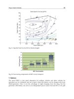
Fig. 1. Some advantages of FPGA use when controlling multiple electric motors.
The main motivation behind the FPGA introduction lies in the following properties: i)high
processing speed; ii
) modularity and parallel capabilities (see Fig. 1) and iii ) hardware
reconfigurability. The first feature, high processing speed, enables a reduction in execution
times of the motor control algorithm, which can been explored to increase the bandwidth
of torque control (Takahashi & Goetz, 2004) and decrease the discretization effects of some
control and estimation techniques (Delli Colli et al., 2010; Naouar et al., 2007). Similarly,
the FPGA parallelism and modularity features open up new possibilities to incorporate
multi-motor control in a single chip, a useful property in multi-axis robotic manipulator
arm (Jung Uk et al., 2009) and in process control applications (Tazi et al., 1999), and develop
fault tolerant control systems with physical redundancy (Seo et al., 2010). Furthermore, even
software based solution implemented in DSPs relies on some special hardware peripherals
to boost time critical tasks, e.g. the pulse with modulators (PWM). Although these fixed
hardware peripherals can be parameterized to address a wide variety of application, there
are some cases where this architecture is unsuitable. The special modulation hardware blocks
that multi-level converters demand is a paradigmatic example of the limitations present in
the fixed DSP architecture. In this case, the FPGA hardware reconfigurability property is
pivotal to effectively solve the multi-level modulation problem by allowing the development
of custom PWM blocks in FPGA logic (Lopez et al., 2008). As additional benefits, the FPGAs
offers the possibility to migrate, if large production volumes are needed, to ASICs - application
specific integrated circuits (Fasang, 2009) - and avoid components obsolescence by emulating
in FPGAs the behaviour of discontinued products, such as processors and others digital
circuits (Guzman-Miranda et al., 2011).
On the other hand, FPGAs also present some potential difficulties and pitfalls that must
be carefully considered before adopting this technology. Firstly, the FPGA unit cost
have been the main obstacle to achieve a wider penetration of this technology, but,
160
Electric Vehicles – Modelling and Simulations
FPGA Based Powertrain Control for
Electric Vehicles 3
owing to the continuous cost reduction in the fabrication processes, this issue is being
attenuated (Rodriguez-Andina et al., 2007). In second place, the designing times and the
learning curve associated with the FPGA tools can also pose some concerns. The most
common approach to design these types of systems is to code directly in hardware description
languages, like Verilog or VHDL. This approach has potential to produce very efficient and
optimized code, but the developing time, although inferior to ASICs (Winters et al., 2006),
is still very high when compared with DSPs. To overcome these difficulties, graphical based
design tools, such as Simulink HDL Coder (MathWorks, 2010) or the System Generator (Xilinx,
2005), were included on the top of the FPGA tool-chain, allowing faster developing times and
a jump start for designers without previous knowledge on hardware design. Another factor
that helps to reduce the developing effort is the integration of processors (hard or soft) within
the FPGA. As a result, the designer has an additional degree of freedom to partitioning the
system project into two components, namely the software and hardware components. The
former runs inside the processor and is responsible for non-time critical tasks, giving easier
and faster develop environments (Barat et al., 2002), while the later is implemented in FPGA
logic and handles the f aster algorithms.
Finally, another traditional limitation in the majority of the FPGAs is the absence of analog
peripherals, like a nalog to digital converters, forcing the inclusion of additional external
components on the control board, which may poses undesirable limitations on embedded
system with high-level of integration requirements. A notable exception to this trend is the
Actel Fusion family (Actel, 2010) t hat supports m ixed-signal p rocessing, and is being used to
develop complete SOC solutions for motor drives applications ( Idkhajine et al., 2009).
To sum up, the FPGAs cost reductions made in the last years, coupled with the new graphical
oriented design tools and the increasingly computational d emands in industrial and vehicular
electronics, are making these reconfigurable system a competitive alternative to ASICs and
DSPs. For that reason, in this work, we explore the FPGAs properties to design and implement
an advanced motion control library for EVs, addressing the most relevant control needs in
modern powertrains, i.e. (multi) motor control, energy loss minimization and vehicle safety
functionalities.
The remaining of the article is structured as follows. Section 2 presents an overview of
the library developed to control the powertrain of multi-motor EV’s. Next, in Section 3,
this powertrain library is used to build a FPGA control system for the uCar EV prototype,
including experimental validation. And finally, Section 4 discusses the conclusions and future
work.
2. Overview of the powertrain IP core library
Inspired by the vector control signal processing blockset for use with Matlab -
Simulink (Araujo & Freitas, 1998), in recent years our team developed a set of Intellectual
Properties (IP) cores, targeting the advanced and efficient powertrain control of EV’s with
multiple motors (Araujo et al., 2009; 2008; de Castro et al., 2010a;b; 2009a;b). This IP core
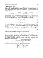
library, whose main components are depicted in Fig. 2, can be divided in 3 main classes.
Firstly, a low level c lass was created containing basic control blocks, like P roportional
and Integral controllers, modulators, mathematical transforms, etc., that were efficient and
carefully designed to be reused in the control of power electronics applications and other
higher level functions. Secondly, a middle layer incorporating motor control and estimation
blocks was developed, in order to regulate the electric motor torque and flux, while
161
FPGA Based Powertrain Control for Electric Vehicles
4 Will-be-set-by-IN-TECH
PI
K
i
K
p
out
Max
in
PI Controller
Park Transform, Low Pass Filter, Integrator, Trignometric Functions, etc
SVPWM
m
T
PWM
a
PWM
b
PWM
c
i
a
i
b
DE
abc
i
a
i
b
Clark Transform
Basic Control
Blocks
Motor Control
and Estimation
i
a
,i
b
i
q
*
,i
d
*
PWM
a
PWM
b
PWM
c
Motor Torque and
Flux Control
T
i
d
*
speed
i
q
i
d
i
q
*
Energy Loss
Minimization
L
m
,L
r
,L
s
r
s
,r
r
Motor Parameter
Identification
Vehicle Safety
O
P
T
in
tire slip
T
out
Traction
Control
T
in
yaw-rate
T
left
Active Torque
Distribution
O
P
T
in
tire slip
T
out
Anti-lock
Braking Control
Speed Observers, Flux Observers, etc…
Friction Observer, Vehicle Speed Observer, Side-slip observer,
T
right
v,i
Fig. 2. Powertrain IP Core library for the control of Electric Vehicles.
minimizing the energy losses in the process. On top of that, a control layer related with the
vehicle safety functions is also available, which aid the driver avoiding high tire slips during
acceleration (traction control) and braking (ABS) manoeuvres and to perform active torque
distribution in multi-motor EVs.
One of the main strengths in this library is that the system designer has a great flexibility to
specify the controller architecture that best fits the design goals, ranging from basic powertrain
controllers (just the motor control) to more advanced solutions with energy minimization
and driving aid systems. T he FPGA parallel features also allow the multiple instantiation
of the same IP core, without degrading the control response time, which is very beneficial
for multi-motor EVs where many blocks may need to be replicated in the same control
unit (de Castro et al., 2010b). Moreover, the library is implemented in a generic hardware
description language (Verilog), so it can be easily ported between different FPGA vendors,
introducing m ore freedom in the hardware s election f or the controller implementation.
It is worth pointing out that the IP core blocks represent "out-of-box" solutions to specific
powertrain control problems, without requiring extensive development times, so the
designer can focus more in the application problems and tuning and less in the technology
development. Although not explicitly represented in Fig. 2, there is also available other
auxiliary IP cores related with communications (UART, SPI, CAN, etc.), memory controllers,
quadrature decoder, soft processors etc., which are normally supplied from the FPGA
manufactures and allow the interface with external peripherals. In the remaining of this
section, a brief overview of the main functionalities of the powertrain library will be discussed.
2.1 Vehic le safety
Active safety systems are of paramount importance in modern transportation applications
and represent an unavoidable functionality to reduce and prevent road accidents (van Zanten,
2002). Therefore, the powertrain control of EVs must address this concern by offering
driving aid mechanisms to mitigate the effects of a loss of the vehicle longitudinal and/or
162
Electric Vehicles – Modelling and Simulations
FPGA Based Powertrain Control for
Electric Vehicles 5
lateral controllability. Such cases may appear due to aggressive driving patterns or, more
importantly, by unavoidable external conditions that limit the vehicle operation range and
make driving more difficult. For example, when the road present low grip conditions, such
as wet tarmac, snow or ice, it is easy for the driver to apply excessive torque to the wheels
and generate high tire slips. As a consequence, this excessive slip may produce tire wear,
reduce the longitudinal force transmitted to the vehicle and compromise the tire capability
to generate lateral forces, i.e. the steerability. In order to improve the longitudinal EV
safety our powertrain control library contains IP cores for performing the traction controller
(TC) and anti-lock braking functions. These control blocks are based on the sliding mode
control framework and, when excessive tire slips are detected, they reduce the wheel torque
magnitude to levels where the tire slip is co nstrained to a safe range, i.e. to a point where the
tire longitudinal force is maximized. The main merit of this approach is the implementation
simplicity and robustness to the model’s parametric variations, s uch as the grip levels present
on the road. These IP cores were experimental verified in our EV prototypes, demonstrating
satisfactory competence in preventing excessive tire slip, particularly under low friction
conditions. For further details about these control blocks, the interested reader is referred
to (de Castro et al., 2010a).
A second important safety function that the powertrain control must address is the torque
allocation/distribution strategy for EV’s driven by multiple motors. Unlike traditional
vehicles, based on internal combustion engine, the high specific power and energy densities
offered by the electric motor opens up new possibilities for the powertrain configuration, in
particular the distribution of several motors by the EV wheels. With these new configurations,
normally composed by 2 or 4 electric motors, the traditional mechanical differentials are
eliminated from the powertrain, as well as its energy losses, and the torque transmitted to each
driven wheel can be independently controlled. Accordingly, this new degree of control can
be explored to perform torque allocation based on the vehicle yaw-rate and side-slip control,
which improve the vehicle handling (He et al., 2005) a nd the lateral safety (Geng et al., 2009).
Although important, this block is still under internal development by our team (de Castro,
2010) and we are planning to incorporate it, as soon as possible, in the powertrain library.
Nevertheless, while this block is not completely developed we are employing a simple
constant torque allocation (de Castro et al., 2009b), whose features will be discussed i n a later
section.
2.2 Motor control, identification and energy minimization
To address t he control of EVs based on induction motors, the well known indirect field
oriented method (Araujo, 1991; Novotny & Lipo, 1996) w as incorporated in the library,
achieving a decoupled control of torque and flux by regulating the motor currents, which
are formulated in the synchronous reference frame and will be briefly discussed in the
next section. Besides the decoupled control, the current feedback loops, on which the
vector control builds, also increases the system robustness against load overloads, peak
current protection and compensation of non-linear effects (e.g. semiconductor voltage drop,
dead-times, DC-link voltage variations, etc.), making this approach very attractive for EV
applications. Furthermore, this module can also be used, with little modifications, to control
other types of motors frequently employed in the EV applications, s uch as permanent magnet
and brushless DC motors (Araujo et al., 2009), and be easily replicated inside the control unit
to address EVs with multi-motor configurations (de Castro et al., 2010b).
163
FPGA Based Powertrain Control for Electric Vehicles