Nuclear Power System Simulations and Operation Part 9 pptx
Bạn đang xem bản rút gọn của tài liệu. Xem và tải ngay bản đầy đủ của tài liệu tại đây (537.56 KB, 15 trang )
A Literature Survey of Neutronic and Thermal-Hydraulics Codes for Investigating
Reactor Core Parameters; Artificial Neural Networks as the VVER-1000 Core Predictor
109
No. Title and authors Coupled codes NPP
Transient
type ef.
11
Analysis of a Boron Dilution Accident for
VVER-440
Combining the Use of the Codes DYN3D and
SiTap
U. Rohde, I. Elkin, V. Kalinenko
SiTap
DYN3D
VVER 440 RIA
Grid
frequency
error
injection test
12
RELAP5-PANTHER Coupled
Code Transient Analysis
B.J. Holmes, G.R. Kimber,
J.N. Lillington, M.R. Parkes
RELAP5
PANTHER
PWR
(Sizewell-B)
Single
turbine
trip event
13
TACIS R2.30/94 Project Transient Anal
y
sis
f
or
RBMK Reactors
H. Schoels, Yu. M. Nikitin Nikiet
FLICA GIDRA SADC
DINAO
CRONOS
QUABOX/CUBOX
RBMK
(Smolensk 3)
RIA
14
PWR Anticipated Transients Without
SCRAM Analyses Using PVM Coupled
RETRAN and STAR 3-D Kinetics Codes
M. Feltus, K. Labowski
RETRAN
STAR 3-D
PWR ATWS
15
Development and First Results of
Coupled Neutronic and Thermal-hydraulics
Calculations for the
High -performance LWR
C.H.M. Broeders, V. Sanchez-Espinoza, A.
Travleev
RELAP5
KAPROS
HPLWR FA tests
16
Analysis and Calculation of an
Accident with Delayed Scram
on NPP Greifswald using the
Coupled Code DYN3D-ATHLET
S. Kliem
ATHLET
DYN3D
VVER-440
(Greifswald)
Delayed
scram
17
Multi-dimensional TMI-1 Main Steam Line
Break Analysis Methodology using TRAC-
PF/NEM
K. Ivanov, T. Beam, A. Baratta, A. Irani, N.
Trikouros
TRAC-PF
NEM
PWR
(B&W TMI-1)
MSLB
18
Realistic and Conservative Rod Ejection
Simulation in a PWR Core at HZP, EOC
with Coupled PARCS and RELAP Codes
J. Riverola, T. Núñez, J. Vicente
RELAP
PARCS
Three-loop
PWR
Peripheral
rod ejection
19
OECD/NRC BWR
Benchmark 3
rd
Workshop
ATHLET
QUABOX/CUBBOX
BWR Peach
Bottom
TT
ATWS: Anticipated Transient without Scram; RIA: Reactivity Induced Accident;
REA: Rod Ejection Accident; MCP: Main Coolant Pump; LOFW: Loss Of proper Feed Water
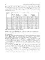
Table 1.(continues) Overview of 3-D coupled neutronics/thermal-hydraulics calculations
available from the literature
Nuclear Power - System Simulations and Operation
110
3.3 Computational Fluid Dynamics (CFD) codes
The strategy of CFD is to replace the continuous domain with a discrete domain using a grid.
The geometry is discretized with a typical mesh size of less than a volume and the thermal-
hydraulics properties are computed for every grid point defined. The conservation equations
for mass momentum and energy are solved in a discrete form. Any complex geometry is
possible, the extremely fine resolution costs computation time. The CFD approach is mostly
preferred for small geometries. Existing CFD codes include: FLUENT, CFX.
4. Coupled neutronic and thermal-hydraulics computer codes for LWR
An overview of available coupled neutronics/thermal-hydraulics code published up to now
has been reported in table 1. This table summarizes a list of coupled codes for PWR, BWR to
date, with the computer codes described in the previous chapters.
4.1 Requirements to the coupling algorithm
Detailed description of the interlace requirement to couple thermal-hydraulics code to 3-D
neutronic code has been reported by Langenbuch et al. The objective to couple neutronics
code with a thermal-hydraulics code is to provide an accurate solution in a reasonable
amount of CPU time. For the present study, the basic components that are considered for
the coupling methodology include:
4.2 Coupling method
There are two different ways of coupling, internal and external coupling. With internal
coupling the neutronics code is integrated within the thermal-hydraulics code. While with
external coupling, the two codes run externally and exchange information between each
other.
4.3 Spatial mesh overlay
Accurate mapping of mesh or volumes between the two codes is important to exchange
information between each other.
4.4 Coupled convergence schemes
A convergence scheme of the two codes needs to be defined. For a final convergence of the
coupled codes, independent convergence in the individual codes is required.
5. Theory of Artificial Neural Network (ANN)
An ANN consists of simple computational units called neurons and it is characterized by a
network structure. The neurons connected to each other with different connection strengths.
The strength of a connection between neurons is called weight. The types of ANNs are
different and associated with applications. The artificial neural networks have a wide
variety of applications in nuclear engineering. Some of the basic related researches are listed
below:
• Fuel management optimization (Faria and Pereira, 2003)
• Prediction of core parameters (Gazula and Bohr, 1992)
• Plant control and monitoring (Uhrig, 1995)
A Literature Survey of Neutronic and Thermal-Hydraulics Codes for Investigating
Reactor Core Parameters; Artificial Neural Networks as the VVER-1000 Core Predictor
111
• Nonlinear dynamics and transient diagnosing (Adali et al., 1997)
• Two-phase flow study (Tambouratzis and Pazsit, 2009)
• Signal validation method (Ikonomopoulos and Van Der Hagen, 1997)
In some investigations to speed up effectively optimization process a very fast estimation
system of core parameters has been introduced and developed using cascade feed forward
type of artificial neural networks.
5.1 ANN designing
Among the literature, there are different types of available network architectures. The most
popular neural network is Multi-Layer Perceptron (MLP) network. This later has been
chosen because of its high performance in predictive tasks (Erdogan and Geckinli, 2003;
Souza and Moreira, 2006) and to let comparison with the results issued from our
calculations. In MLP, various neurons are arranged in different layers called input, hidden,
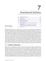
and output. Fig. 1 shows a typical scheme of the three layers neural network. The neurons
in the first layer correspond to independent input variables of the problem and transmit the
input values to the succeeding layer. After the input layer, there may be one or more hidden
layers. They receive the weighted combination of input values from the preceding layer and
produce an output depending on their activation function (Jodouin, 1994). As shown in
figure 1, the weights are determined and adjusted, through an iterative and a back-
propagation process, minimizing a quadratic error function. Thus, to make use of an
appropriate Artificial Neural Network, one must fine-tune the following items as their
incidence on the prediction parameters are of a crucial importance.
The items of interest are as follow:
1. Activation function,
2. Performance function,
3. Training algorithms.
Fig. 1. Typical architecture of Multi-Layer Perceptron (MLP) neural network
Nuclear Power - System Simulations and Operation
112
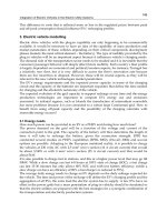
5.2 Cascade feed forward neural networks
A general type of feed-forward ANNs consists of a layer of inputs, a layer of output
neurons, and one or more hidden layers of neurons. Figure 2 shows a general type of a three
layers feed-forward ANN. Typically feed-forward ANNs are used to parameter prediction
and data approximation.
Fig. 2. A general type of three layered feed-forward ANNs
A cascade type of feed-forward ANNs consists of a layer of input, a layer of output neurons,
and one or more hidden layers. Similar to a general type of feed-forward ANNs, the first
layer has weights coming from the input. But each subsequent layer has weights coming
from the input and all previous layers. All layers have biases. The last layer is the network
output. Each layer’s weights and biases must be initialized. A supervised training method is
used to train considered cascade feed forward ANNs.
5.3 Training and activation functions
The training process determined through a back propagation algorithm which minimizes a
quadratic error between the desired and network outputs. The gradient descent method
with momentum weight/bias learning rule has been used to train considered ANNs. It is a
developed algorithm of the basic back propagation algorithm (Hagan et al., 1995; Rumelhart
et al., 1986a,b). A net input (V
j
) to a neuron in a hidden layer k is calculated by this formula
(Eq. (1)).
1
n
jj
ii
j
i
VW
θ
θ
=
=
+
∑
(1)
Where n is the number of k-1 layer neurons for a general type of feed-forward ANNs and
the number of all of the previous layer neurons for a cascade type of feed-forward ANNs.
Weights are noted by W
ji
; and the threshold offset by θ
j
.
A Literature Survey of Neutronic and Thermal-Hydraulics Codes for Investigating
Reactor Core Parameters; Artificial Neural Networks as the VVER-1000 Core Predictor
113
The output of the neuron O
j
is given by an activation function. An activation derivative
function effects on neuron outputs to compress propagated signals and simulate the
nonlinearity of the complex systems. Many different activation functions are used in feed-
forward ANNs. There are several types of activation functions such as Linear (Eq. (2)), Log-
Sigmoid (Eq. 3), Tan-Sigmoid (Eq. 4) functions, etc.
()
jj
O Pureline V
=
(2)
(
)
()
()1/1
j
V
jj
OLogsigV e
−
==+ (3)
(
)
2( ) 2( )
() 1 /(1
jj
VV
jj
OTansigV e e
−
−
==−+
(4)
In this learning method, which is a batch training method, weights and biases are only
updated after all the inputs and targets are presented to ANNs. Then the average of system
error (Eq. 5) should be minimized to increase learning performance.
()
2
11
1
() ()
2
NM
AV j j
ij
EdnOn
N
==
=−
∑∑
(5)
Where d
j
(n) is the desired output; and O
j
(n) is the network output. N and M are the total
number of training data sets and the number of neurons of the output layer. In the gradient
descent method improved values of the weights can be achieved by making incremental
changes Δw
ji
proportional to ∂E
AV
/∂W
ji
(Eq. 6).
A
V
ji
j
i
E
W
W
η
∂
Δ=−
∂
(6)
Where the proportionally factor η is called the learning rate. Large values of η in the
gradient descent formulation may lead to large oscillation or divergence. One attempt to
increase the speed of convergence while minimizing the possibility of oscillation, or
divergence, involves adding a momentum term to the basic gradient descent formulation. In
this case the weight vector at time index (k+1) is related to the weight vectors at time
indexes (k) and (k-1) by this formula (Eq. 7).
(1) () (1)
E
Wk Wk Wk
W
ηβ
∂
⎡
⎤
+= − +Δ −
⎢
⎥
∂
⎣
⎦
(7)
Then the new weights for step (k+1) are given by:
(1) ()
ji j j ji
Wk O Wk
η
δβ
Δ
+= +Δ (8)
Where a momentum coefficient, or an acceleration parameter β is used to improve
convergence. The expression of δ
j
is given by:
0.5( ) ( )
kkkk
dOfv
δ
′
=
− (9)
( ) for hidden neurons
jkkkj
k
fv W
δδ
′
=
∑
(10)
Nuclear Power - System Simulations and Operation
114
It should be noted that the technology of ANNs has been still developing. The determination
of minimum number of necessary hidden neurons and hidden layers is completely practical.
If the hidden neurons are chosen very small, the network will classify its input in a small
number of classes (Wilde, 1997). If the hidden neurons are selected extremely large, the time
of learning process increases ineffectively. Presently, the best method is making an educated
guess. In this work, after primarily studies some practical tests are suggested and used to
adjust the main parameters and properties of the ANNs’ structures and used training rule
(Eqs. 1 through 10).
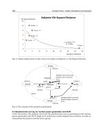
5.4 ANN development strategy
The motivation in using such a computational procedure lies in the fact that it will let us use
just hundreds of configurations rather than the thousands, in the learning stage, that are
usually required in typical calculations to ensure reasonable predictions. Hence, as shown in
Fig. 3, a suitable neural networks development strategy can be tested based on executing the
following two main calculational stages, in an independent way: learning stage and
prediction stage.
Initial Core
cofiguration
Transformation
Input pattern
Transformation
Input pattern
Initialize
Weights
Calculate
Output
Calculate
Output
Adjust weights to
minimize error
Save
weights
Compare
Error < ε
Yes
No
1
1
Core parameters
calculator software
1
Neutronic (Keff, Peaking factor, …)
Thermal -Hydraulic(Heat flux ,
DNBR, CHF) parameters
2
2
Validation
Prediction Stage
Learning Stage
2
Fig. 3. Overall back-propagation computational strategy for the core parameter prediction
A Literature Survey of Neutronic and Thermal-Hydraulics Codes for Investigating
Reactor Core Parameters; Artificial Neural Networks as the VVER-1000 Core Predictor
115
The first stage of computational procedure consists of creating suitable networks by
applying an appropriate learning rule using a desired database. The information required in
the related database will contain coupled input values with the corresponding target output
values. These values are used to train the networks until the error reaches a desired value
stated at the beginning of the learning process. It becomes evident that the quality of the
results obtained will depend on how well knowledge is capitalized in this database. Hence,
significant attention will be focused on how well this database will be created. The main
steps required in the learning process are:
1.
Create the database for training;
2.
Construction of networks for training;
3.
Choosing a learning function;
4.
Train the developed networks;
The second stage is the prediction one where the weights, from the inter-connected neurons,
have been adjusted to the desired error in the previous calculations stage. These weights
will be used in a global computational sequence, to predict the networks outputs when
unseen data will be presented to the developed networks. This is the power of the network
approach and one of the reasons for using it. The net is said to have been generalized from
the training data. This stage is necessary to test the performance of the developed neural
network.
5.5 Create data-base for training
A wide variety of completely different core arrangements are needed to train effectively
considered ANNs. In this work, the fuel assembly positions are considered changeable in
calculations. Core calculations have been done by a supporting software tool that will be
able to calculate neutronic and thermal hydraulic parameters of a typical reactor core. This
program uses a coupling method to calculate reactor core parameters for desired core
configuration. Needed parameters for training should be extracted from the software
calculations. They must be converted to a compatible format to feed desired ANNs. Doing
this manually takes a long time while some human errors are possible. In this research, a
data base builder program is designed and used. It is used to create data sets necessary to
train and test considered ANNs.
In this research, a software package (Core Parameters Calculator) is developed and used.
The random state of the software is used to create data sets necessary to train and test used
ANNs. Many strings composed of specific integer numbers are chosen randomly to form
different core configurations. For each different state (configuration), Core Parameters
Calculator software uses MCNP and COBRA-EN code to extract needed neutronic and
thermal-hydraulics core parameters. During calculation process, MCNP code uses cross
sections library provided by NJOY program. Then calculated fission powers of fuel rods
send to Thermal-hydraulics code for calculating of density and temperature distribution of
fuel and coolant. Finally the results (consist of neutronic and thermal- hydraulic parameters)
are stored on a local data base table. Figure 4 shows the main diagram of creating desired
data.
5.6 Developing of a supporting tool for core parameters calculation
Due of the strong link between the water (moderation) and the neutron spectrum and
subsequently the power distribution, a coupling of neutronics and thermal-hydraulics has
Nuclear Power - System Simulations and Operation
116
Data base
tables
Core parameters
calculator software
Outputs
Thermal -
Hydraulic code
Cross -section
Generation code
Neutronic
code
Coupling structure
sending
recieving reading
storing
Fig. 4. The main diagram of creating desired data
become a necessity for reactor concepts operating at real conditions. The effect of neutron
moderation on the local parameters of thermal-hydraulics and vice-verse in a fuel assembly
has to be considered for an accurate design analysis. In this study, the Monte Carlo N-
Particle code (MCNP) and the sub-channel code COBRA-EN (Sub-channel Thermal-
hydraulics Analysis of a Fuel Assembly for LWR) have been coupled for the design analysis
of a fuel assembly and core with water as coolant and moderator. Both codes are well
known for complex geometry modeling. The MCNP code is used for neutronics analyses
and for the prediction of power profiles of individual fuel rods. The sub-channel code
COBRA for the thermal- hydraulics analyses takes into account the coolant properties as
well as separate moderator channels.
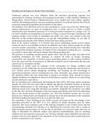
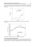
The coupling procedure is realized automatically. MCNP calculates the power distribution
in each fuel rod, which is then transferred into COBRA to obtain the corresponding thermal-
hydraulics conditions in each sub-channel. The new thermal-hydraulics conditions are used
to generate a new input for the next MCNP calculation. This procedure is repeated until a
converged state is achieved. The parameters that are exchanged between the two codes for
the coupling are: power distribution from MCNP code, water density distribution, water
temperature distribution and fuel temperature distribution from COBRA code, as shown in
Figure 5. The COBRA-EN code, which is written in FORTRAN language, is modified to
include the power distribution obtained from neutronics analysis and to be able modeling of
Russian fuel type.
The nuclear cross section data library of MCNP must be provided for additional
temperatures and must be added to MCNP data directory. The cross section data for
neutron interaction are obtained from the evaluated MCNP libraries ENDF/B. Cross section
data provided with the MCNP are for a limited number of temperatures. An additional
library must be constructed from NJOY code with more temperatures (300 K, 500 K, 600 K,
760 K, 800 K, 1000 K, 1500 K) and is added to the MCNP data directory. The coupled code
system was tested on a proposed fuel assembly design of a VVER-1000. The coupling
A Literature Survey of Neutronic and Thermal-Hydraulics Codes for Investigating
Reactor Core Parameters; Artificial Neural Networks as the VVER-1000 Core Predictor
117
procedure presented will also be applicable to other types of reactors with a density
variation in the core such as in BWR.
NJOY
Neutron Cross
Section
MCNP code
Neutronics analysis
COBRA-EN code
Thermal-hydraulics sub -
channel analysis
Power distribution in the fuel
rods
Fuel, clad and
coolant temperature
distribution
Wate r de ns ity dis tribution
in the s ub-c hannels
Fig. 5. Coupled MCNP/COBRA-EN for joining neutronic –thermalhydraulics are shown
schematically. The cross sections modification are a major concern which are doen using
NJOY code
From the literature review, most of the available coupled codes for neutronics/thermal-
hydraulics are based on diffusion and system codes resulting in a rather coarse resolution of
the core. For a detailed analysis of a VVER-1000 fuel assembly analysis, diffusion codes and
system codes are not giving enough local information. All prior application had been to
PWR and BWR transient analysis. To accurately analyze a VVER fuel assembly a more
detailed analysis fuel rod wise and sub-channel wise is required to predict a hot spot and
the temperature distribution around the circumference of a fuel rod. In order to perform
such detailed analysis of the VVER fuel assembly, a new coupled code system is required.
From the reviewed neutronics and thermal-hydraulics computer codes, the Monte Carlo
code and sub-channel codes show to be the best choice of codes to be coupled for detailed
fuel assembly analysis. Both have similar spatial resolution. The smallest control volume is
in the order of a few cm in both cases. System codes on the other hand would be too coarse
for MCNP and CFD codes too fine in resolution.
6. Conclusions
Obviously, due to huge files, it is not possible to present our input files ( MCNP and
COBRA-EN codes) as our suggested package in this chapter, but reader can consult the
Nuclear Power - System Simulations and Operation
118
corresponding author to find the MCNP as well as COBRA-EN input files for simulating a
VVER-1000 reactors. The MCNP code contains hexagonal core including all core conditions
such as all control rod inserted (or withdrawn), boric acid inserted, hot full power condition,
etc. Also, reader can find our COBRA-EN code to undrestand how we can simulate thermal
hydraulics subchannels of a VVER-1000 reactor. Moreover, as we said previously,
temperature cross sections modification are carried out using NJOY code and obviously
reader can receive our modification. These so-called data are used as output data for ANN
training. If reader are interested, they can consult the corresponding author to get our ANN
simulator. Basically, the main objective of the ANN software is to obtain fast estimation
tool which allows large explorations of core safety parameters. This software is very useful
in reactor core designing and in-core fuel management or loading pattern optimization.
In due course, verification and validation of the procedures are taking into account using
available experimental data or other code-to-code benchmarking, and this is an important
part of research.
7. References
Adali, T., Bakal, B., Sönmez, M.K., Fakory, R., Tsaoi, C.O., 1997. Modeling nuclear reactor
core dynamics with recurrent neural networks. Neurocomputing 15 (3–4), 363–
381.
Allaire, G.: Solving Linear System Equation in FLICA, A Thermo-Hydraulic Code for 3-D
Transient Computations, Proc. International Conference on Mathematic and
Computations, Reactor Physics and Environmental Analyses.
Asaka, H., Zimin, V.G., Iguchi, T., Anoda, Y.: Coupling of the Thermal-hydraulics codes
with 3D Neutron Kinetic Code SKETCH-N, Preliminary Proceedings of the
OCED/CSNI Workshop on Advanced Thermal-hydraulics and Neutronics Codes:
Current and Future Applications, Vol.2, pp. 1 — 15, Barcelona, Spain, 2000
Bousbia-Salah, A. et al.: Analysis of the Peach Bottom Turbine Trip 2 Experiment by
Coupled RELAP-PARCS Three-Dimensional Codes, Nuclear Science and
Engineering, Vol. 148, pp337– 353, 2004.
Bovalini, R., D’Auria, F., Galassi, G.M., Spadoni, A., Hassan, Y.: TMI-MSLB Coupled 3-D
Neutronics/Thermal-hydraulics Analysis: Application of RELAP5-3D and
Comparison with Different Codes, RELAP5 International Users Seminar, Sun Vally,
Idaho, 2001.
Briesmeister J.F, Editor, MCNP – A General Monte Carlo N-Transport code, Version 4C, Los
Alamos National Laboratory report LA-12625, 1993.
Broeders, C.H.M., Dagan, R., Sanchez-Espinoza, V, Travleev, A.: KAPROS-E: Modular
Program System for Nuclear Reactor Analysis, Status and Results of Selected
Applications, Jahrrestagung Kerntechnik, Diisseldorf, 2004.
Burwell, M.J.,Lerchl, G., Miro, J., Teschendorff, V., Wolfert, K.: The Thermal-hydraulics
Code ATHLET for Analysis of PWR and BWR Systems, Proceedings Fourth
International Topical Meeting on Nuclear Reactor Thermal-hydraulics, Vol. 2, pp
1234 – 1239, Oct. 10 – 13th,1989.
CFX-4 User Manual,1997, AEA Technology,
A Literature Survey of Neutronic and Thermal-Hydraulics Codes for Investigating
Reactor Core Parameters; Artificial Neural Networks as the VVER-1000 Core Predictor
119
Cheng, X., Schulenberg, T., Bittermann, D., Rau, P.: Design Analysis of Core Assemblies for
Supercritical Pressure Condition, Nuclear Engineering and Design, 223, 279-294,
2003.
Erdogan, A., Geckinli, M., 2003. A PWR reload optimisation code (XCore) using artificial
neural networks and genetic algorithms. Ann. Nucl. Energy 30,35–53.
Faghihi, F., Fadaie, A.H., Sayareh, R. Reactivity coefficient simulation of the Iranian VVER-
1000 nuclear reactor using WIMS and CITATION codes. Prog. Nucl. Energy 49, 68–
78. 2007.
Faghihi, F.; Saidinezhad, M.; 2011. Two safety coefficients for 13×13 annular fuel assembly,
Prog. Nuclear Energy 53, pp.250-254.
Faghihi et al.; 2010. Modified COBRA_EN code for investigating Iranian VVER-1000 reactor,
Prog. Nucl. Energy 52, pp. 289-295.
Faria, E.F., Pereira, C., 2003. Nuclear fuel loading pattern optimization using a neural
network. Annals of Nuclear Energy 30 (5), 603–613.
Fluent 5 Users Guide, Fluent Inc., Lebanon, NH (1998); .
Fu, H., Rodarte, J.S., Ivanov, K.N.: TRAC-PF1/NEM Modelling and Results of
OECD/NEA BWR core Transient Benchmarks, Annals of Nuclear Energy, 27,
1051 – 1058, 2000.
Gazula, S., Bohr, J.W.C., 1992. Learning and prediction of nuclear stability by neural
networks. Nuclear Physics A 540 (1–2), 1–26.
Glaeser, H.: Validation and Uncertainty Analysis of the ATHLET code Thermal-hydraulics
computer code, Nuclear Society of Slovenia, 2nd Regional Meeting: Nuclear Energy
in Central Europe Portoroz, Slovenia, 1995.
Grundmann, U., S. Mittag and U. Rohde, Dyn3d2000/M1 for the Calculation of Reactivity
Initiated Transients in LWR with Hexagonal and Quadratic Fuel Elements – Code
Manual and Input Data Description for Release, 3rd Edition, Research Center
Rossendorf Inc., Sept. 2001.
Grundmann, U., Lucas, D., Rohde, U.: Coupling of the Thermo-hydraulic Code ATHLET
with the Neutron Kinetic Core Model DYN3D, Proc. International Conf. on
Mathematics and Computation, Reactor Physics and Environmental Analyses.
Grundmann, U., Kliem, S., and Rohde, U.: Analysis of the Boiling Water Reactor Turbine
Trip Benchmark with the Codes DYN3D and ATHLET/DYN3D. Nuclear Science
and Engineering, Vol. 148, Page 226 – 234, 2004.
Hagan, M.T., Demuth, H.B., Beale, M.H., 1995. Neural Network Design. PWS Pub. Co.,
Har/Dsk Edition.
Holland, J.H., 1975. Adaptation in Natural and Artificial Systems. University of Michigan,
Ann Arbor.
Ikonomopoulos, A., Van Der Hagen, T.H.J.J., 1997. A novel signal validation method
applied to a stochastic process. Annals of Nuclear Energy 24 (13), 1057–1067.
Ivanov, K., et al., “Nodal Kinetic Model Upgrade in The Penn State Coupled TRAC/NEM
Codes”, Annl. Nucl. Ener., 26, 1205 (1999).
Ivanov K.N., Juan, R.M., Irani, A., Baratta, A.J.: Features and Performance of a Coupled
Three Dimensional Thermal-hydraulics/kinetics TRAC-PF1/NEM PWR analysis
code, annals of Nuclear Energy 26, 1407 —1417, 1999.
Nuclear Power - System Simulations and Operation
120
Jackson, C.J., Finnemann, H.: Verification of the Coupled RELAP/PANBOX System
with the NEACRP LWR Core Transient Benchmark, Proc. International
Conference on Mathematic and Computations, Reactor Physics and
Environmental Analyses
Jodouin, J.F., 1994. Les Réseaux Neuromimétiques, Modèles et Applications. Edit. Hermès,
Paris.
Joo, H.G., D.A. Barber, G. Jiang and T.J. Downar, PARCS: A Multidimensional Two-group
Reactor Kinetic Code Based on the Non-linear Analytical Nodal Method,
University of Purdue Report PU/NE-98-26 (1998).
Kim, H.G., Change, S.H., Lee, B.H., 1993. Pressurized water reactor core parameter
prediction using an artificial neural network. Nuclear Science and Engineering
113,10–76.
Kirkpatrick, S., Gellat, C.D., Vecchi, M.P., 1983. Optimization by simulated annealing.
Science 220 (4598), 671–680.
Langenbuch, S., QUABBOX/CUBBOX-HYCA, Ein Dreidimensionales Kernmodell mit
parallelen Kühlkanälen für Leichtwasser-reaktoren, GRS-A-926, Garching,
Germany (1984).
Langenbuch, S., Austregesilo, P., Fomitchenko, P., Rohde, U., Velkov, K.: Interface
Requirements to Couple Thermal-Hydraulics Codes to 3D Neutronic Code,
OCED/CSNI Workshop on Transient Thermal-hydraulics and Neutronic Codes
Requirements, Annapolis, United State, 1996.
Lee, D et al.: Analysis of the OECD/NRC BWR Turbine Trip Transient Benchmark with the
coupled Thermal-hydraulics and Neutronics Code TRAC-M/PARCS, Nuclear
Science and Engineering, Vol. 148, Page 291 – 305, 2004
Lee, D., Downar, T.J., and Kim, Y.: A Nodal and Finite Difference Hybrid Method for Pin-by
Pin Heterogeneous Three-Dimensional Light Water reactor Diffusion Calculations,
Nuclear Science and Engineering, Vol. 146, pp. 319 — 339, 2004
Mazrou, H., Hamadouche, M., 2004. Application of artificial neural network for safety core
parameters prediction in LWRRS. Progress in Nuclear Energy 44 (3), 263–275. Fuel
and Energy Abstracts 46 (1), 14, January 2005.
Miller, M.R., Downar, T.J.: Completion Report for the Coupled TRACS-M/PARCS Code,
University of Purdue, Report PU/NE-99-20.
Mignot, G., Royer, E., Rameau, B., Todorova, N.: Computation of a BWR Turbine Trip with
CATHARE-CRONOS2-FLICA4 Coupled Codes, Nuclear Science and Engineering,
Volume 148, Page 235 – 246, 2004.
Misu, St., Kiehlmann, H.D., Spierling, H., Wehle, F.: The Comprehensive Methodology for
Challenging BWR Fuel Assembly and core Design used in Framatome ANP,
Physor, Seoul, Korea, 2002.
Mori, M., Rineiski, A., Kretzschmar, F., Maschek, W., Morita, K.: Coupled MCNP/MXN
Calculations for the SCFR, CAPRA-CADRA, International Seminar, Aix-en-
Provence, France,2004.
Mori, M., Maschek, W., Laurien, E., Morita, M.: Monte-Carlo/Simmer-III Reactivity
Coefficient Calculation for the Super-Critical Water Fast Reactor, Proc. of the
ANS/ENS Topical Meeting GLOBAL, New Orleans, 2003.
A Literature Survey of Neutronic and Thermal-Hydraulics Codes for Investigating
Reactor Core Parameters; Artificial Neural Networks as the VVER-1000 Core Predictor
121
Nigro, A.L., Spadoni, A., D’Auria, F., Saiu, G.: MSLB Coupled 3D Neutronics-Thermal-
Hydraulics Analysis of a Large PWR using RELAP5-3D, International Conference
Nuclear Energy in Central Europe, Portoroz, Slovenia, 2001.
Oak Ridge National Laboratory, 1972. CITATION-LDI2 code.
Pautz, A., and Birkhofer, A.: DORT-TD: A Transient Neutron Transport Code with Fully
Implicit Time Integration, Nuclear Science and Engineering, Vol. 145, pp. 299 —
319, 2003
Pautz, A., Hesse, U., Zwermann, W., Langenbuch, S.: Fuel Assembly Calculation Using the
Method of Discrete Ordinates, Nuclear Science and Engineering, Vol. 149, pp. 197
— 210, 2005.
Pazsit, I., Kitamura, M., 1996. The rule of neural networks in reactor diagnostics and control.
Advances in Nuclear Science and Technology 24, 95–130.
Rhoades W. A., Childs R. L.: TORT-DORT, Two- and Three-Dimensional Discrete Ordinates
Transport, Version 2.7.3, RSIC-CCC-543, ORNL RSICC, Oak Ridge, TN (1993).
Rumelhart, D.E., Hinton, G.E., Williams, R.J., 1986b. Learning internal representations by
error propagation. In: Parallel Data Processing, vol. 1. The MIT Press, Cambridge,
MA, pp. 318–362. (Chapter 8).
Sanchez-Espinoza, V.H., Hering, W., Knoll, A., Boeer, R.: Analysis of the OCED.NEA PWR
Main Steam Line Break (MSLB) Benchmark Exercise 3 with coupled code system
RELAP5/PANBOX, Wissenschaftliche Berichte, FZKA- 6518, 2002.
Sanchez-Espinoza, V., Hering, W., Knoll, A.: Analysis of the OECD/NEA PWR MSLB
Benchmark Exercise 1 using the RELAP5 Code with Point Kinetics Option, FZKA
6427, 2002.
Sanchez-Espinoza, V., Hering, W.: Investigations of the Appropriateness of RELAP5/MOD3
for the Safety Evaluation of an Innovative Reactor Operated at Thermodynamically
Supercritical Conditions, FZKA 6749, 2002.
Souza, R.M.G.P., Moreira, J.M.L., 2006. Neural network correlation for power peak factor
estimation. Ann. Nucl. Energy 33, 594–608.
Turinsky, P.J., et al., NESTLE: A Few-group Neutron Diffusion Equation Solver Utilizing the
Nodal Expansion Method for Eigenvalue, Adjoint, Fixed-source Steady State and
Transient Problems, EGG-NRE-11406, Idaho National Engineering Laboratory,
June 1994.
Uhrig, R.E., 1991. Potential application of neural networks to operation of nuclear power
plants. Nuclear Safety 32.
Uhrig, R.E., 1993. Use of neural networks in nuclear power plants. ISA Transactions 32 (2),
139–145.
Wheeler, C.L., Stewart, C.W., Cena, R.J., Rowe, D.S., Sutey, A.M.: COBRA-IV –I, An Interim
Version of COBRA for Bundle Nuclear Fuel Element and Cores, BNWL-1962, UC-
32, March 1976.
Wilde, P.D., 1997. Neural Network Models. Theory and Projects. Springer, London, p.40.
Winfrith, 1982. LWR-WIMS, a Computer Code for Light Water Reactor Calculations. AEE,
UK. AEEW-R 1498.
Yoo, Y.J., and Hwang, D.H.: MATRA, Multichannel Analyzer for Steady States and
Transients in Rod Arrays, Korea Atomic Energy Research Institute, October 2003.
Nuclear Power - System Simulations and Operation
122
Ziabletsev, D.N., Ivanov, K.N.: Improved verification methodology for TRAC-PF1/NEM
Using NEA/OECD Core Transient Benchmarks, Annals of Nuclear Energy, 27,
1319 – 1331, 2000.
7
Recent Trends in Mathematical Modeling and
Simulation of Fission Product Transport
From Fuel to Primary Coolant of PWRs
Nasir M. Mirza, Sikander M. Mirza and Muhammad J. Iqbal
Department of Physics and Applied Mathematics,
Pakistan Institute of Engineering and Applied Sciences, Nilore, Islamabad 45650,
Pakistan
1. Introduction
With over 437 operational power plants, nuclear systems contribute 370705 MW(e) worldwide
[1]. The Pressurized Water Reactors (PWR) constitute a two-third majority of the operational
nuclear power plants while the nuclear reactors in planning and construction phases also
show strong trend towards PWRs. These systems are mainly used as baseline load carriers
while conventional fossil fueled systems are used for load adjustments and variations [2].
The PWRs have higher than average levels of radiation fields emanating from the corrosion
and fission product activity [3] [4] [5]. This leads to prolongation of maintenance schedules
entailing loss of revenues mounting to several million dollars per plant annually [6].
Consequently, the plant availability factors are also lowered. This situation is further
aggravated due to strong shift of plant age profile toward over 25 years operational range.
With plant aging, the fuel failures become more frequent which leads to enhancement of
radiation levels in the primary circuits of PWRs.
The levels of fission product activity (FPA) have been of concern both from the operational
as well as from accidental perspectives. These levels are continuously monitored during the
normal operation of PWRs. The fuel pins develop leakages with their burnup. When the
failed fuel fraction exceeds a safe limit, replacement of defective assemblies by refueling
becomes necessary. Therefore, low levels of leaked-out fission products (FPs) in primary
coolant of PWRs are indicative of the core health [7]. In the accidental conditions, the total
value of FPA serves as the available source term that potentially can escape into the
surroundings [8] [9].
The fission products are released in the fuel matrix during burnup. They escape from the
ceramic pellets into the gap between pellets and the clad regions. Hyun et al. [10] have
developed an analytic method for the fuel rod gap inventory of unstable fission products
during steady state operation of PWRs. The fission gas bubbles escape from grain corners
and are interlinked in the open space. The release rate depends on the bubble interlinkage
along with temperature and burnup. A generalized model for fission product transport in
the fuel-to-sheath gap was given by Lewis [11]. Barrachin et al. presented a review of fission
product behaviour in UO
2
fuel [12].