Nuclear Power System Simulations and Operation Part 11 docx
Bạn đang xem bản rút gọn của tài liệu. Xem và tải ngay bản đầy đủ của tài liệu tại đây (532.18 KB, 15 trang )
8
Thermal-Hydraulic Simulation of
Supercritical-Water-Cooled Reactors
Markku Hänninen and Joona Kurki
VTT Technical Research Centre of Finland
Tietotie 3, Espoo, FI-02044 VTT,
Finland
1. Introduction
At supercritical pressures the distinction between the liquid and gas phases disappears, and
any fluid stays in a single continuous phase: no evaporation or condensation is observed. At
supercritical state the thermo-physical properties of the fluid, such as density and viscosity,
change smoothly from those of a liquid-like fluid to those of a gas-like fluid as the fluid is
heated. Because of the single-phase nature, a one-phase model would be ideal for thermal-
hydraulic simulation above the critical pressure. However, in the nuclear power plant
applications the one-phase model is not sufficient, because in transient and accident
scenarios, the pressure may drop below the critical pressure, turning the coolant abruptly
from a one-phase fluid into a two-phase mixture. Therefore the thermal-hydraulic model
has to be able to reliably simulate not only supercritical pressure flows but also flows in the
two-phase conditions, and thus the six-equation model has to be used.
When the six-equation model is applied to supercritical-pressure calculation, the questions
how the model behaves near and above the critical pressure, and how the phase transition
through the supercritical-pressure region is handled, are inevitably encountered. Above the
critical pressure the latent heat of evaporation disappears and the whole concept of phase
change is no longer meaningful. The set of constitutive equations needed in the six-equation
solution including friction and heat transfer correlations, has been developed separately for
both phases. The capability of constitutive equations, and the way how they are used above
the supercritical pressure point, have to be carefully examined.
In this article, the thermal hydraulic simulation model, which has been implemented in the
system code APROS, is presented and discussed. Test cases, which prove the validity of the
model, are depicted. Finally, the HPLWR concept is used as a pilot simulation case and
selected simulation results are presented.
2. Modeling of supercritical fluid thermal hydraulics
One possibility to maintain separate liquid and gas phases in the supercritical flow model is
to use a small evaporation heat, and then apply the concept of the pseudo-critical line. The
pseudo-critical line is an extension of the saturation curve to the supercritical pressure
region: it starts from the point where the saturation curve ends (the critical point), and it can
Nuclear Power - System Simulations and Operation
140
be thought to approximately divide the supercritical pressure region to sub-regions of
pseudo-liquid and pseudo-gas. The thermo-physical properties of water and steam undergo
rapid changes near the pseudo-critical line and therefore the quality and accuracy of the
steam tables is essential in calculation of flows under supercritical conditions. One difficult
problem is related to the heat transfer at supercritical pressures; if the ratio of the heat flux
to mass flux exceeds certain value and flow is directed upwards, the heat transfer rate may
suddenly be reduced, and remarkable heat transfer deterioration may occur. The same
phenomena may occur due to flow acceleration. The present heat transfer correlations are
not able to predict properly this phenomenon. However, in conditions where this heat
transfer impairment does not occur, heat transfer rates can be predicted with a reasonable
accuracy using the currently-available correlations. Another issue that has to be taken into
account in thermal hydraulic simulations of SCW reactors is the possible appearance of flow
instabilities. Similarly to the boiling water reactors, instabilities in the core of SCWR may
appear when the ratio of the heat flux to mass flux exceeds a certain value.
3. Solution principles of the six-equation model
At present, the system-scale safety analyses of nuclear power plants are generally calculated
using the six-equation flow model. The safety analyses conducted for a particular nuclear
power plant include mainly different loss-of-coolant scenarios, where the pressure in the
primary circuit decreases at a rate depending on the size of the break. This means that also
in the case of supercritical-water-cooled reactors, boiling may occur during accident
conditions, and therefore also the simulation tools used for the safety analyses of the
SCWR's have to be able to calculate similar two-phase phenomena as in the present nuclear
reactors. A practical way to develop a supercritical pressure safety code, is to take a present
code and modify it to cope with the physical features at supercritical pressures.
The six-equation model of APROS used for the two-phase thermal hydraulics is based on
the one-dimensional partial differential equation system which expresses the conservation
principles of mass, momentum and energy (Siikonen 1987). When these equations are
written separately for both the liquid and the gas phase, altogether six partial differential
equations are obtained. The equations are of the form
k
kkkkk
=
z
uρα
+
t
ρα
Γ
)()(
∂
∂
∂
∂
, (1)
kkkkkk
kkkkkk
F+F+gρα+u=
z
uρα
+
t
uρα
iwi
2
Γ
)()(
G
∂
∂
∂
∂
, (2)
kkkkkkkk
kkkkkkk
uF+uF+q+h+
t
p
α=
z
huρα
+
t
hρα
iiwii
Γ
)()(
∂
∂
∂
∂
∂
∂
. (3)
In the equations, the subscript k is either l (= liquid) or g (= gas). The subscript i refers to
interface and the subscript w to the wall. The term Γ is the mass change rate between phases
(evaporation as positive), and the terms F and q denote friction force and heat transfer rate.
For practical reasons, the energy equation (3) is written in terms of the total enthalpy, which
equals to conventional “static” enthalpy plus all the kinetic energy:
2
stat
2u/1+h=h
.
Thermal-Hydraulic Simulation of Supercritical-Water-Cooled Reactors
141
The equations are discretized with respect to space and time and the non-linear terms are
linearized in order to allow the use of an iterative solution procedure (Hänninen & Ylijoki).
For the spatial discretization a staggered scheme has been applied, meaning that mass and
energy balances are solved in one calculation mesh, and the momentum balances in another.
The state variables, such as pressure, steam volume fraction, as well as enthalpy and density
of both phases, are calculated in the centre of the mass mesh cells and the flow related
variables, such as gas and liquid velocities, are calculated at the border between two mass
mesh cells. In solving the enthalpies, the first order upwind scheme has been utilized
normally. In the mesh cell, the quantities are averaged over the whole mesh, i.e. no
distribution is used.
In the case of the APROS code, the main idea in the solution algorithm is that the liquid and
gas velocities in the mass equation are substituted by the velocities from the linearized
momentum equation. In the momentum equation the linearization has been made only for
the local momentum flow. For the upwind momentum flows the values of the previous
iteration is used. In addition the phase densities are linearized with respect to pressure. The
density is linearized as
()
pp
p
ρ
+ρ=ρ
n
k
k
n
k
−
∂
∂
, (4)
where the superscript n refers to the value at the new time step. When this linearization is
made together with eliminating phase velocities with the aid of the linearized momentum
equation, a linear equation group, where the pressures are the only unknown variables is
formed. Solution of this equation system requires that the derivatives of density are always
positive, and also the phase densities obtained from the steam table are increasing with
increasing pressure.
In the one-dimensional formulation, phenomena that depend on gradients transverse to the
main flow direction, like friction and heat transfer between the gas and liquid phases, and
between the wall and the fluid phases, have to be described through constitutive equations,
which are normally expressed as empirical correlations. These additional equations are
needed to close the system formed by six discretized partial differential equations.
4. Application of the six-equation model to supercritical-pressure flow
When the six-equation model is applied to supercritical-pressure calculation, the problems
how the model behaves near and above the critical pressure, and how the phase transition
needed in two-phase model is handled when the pressure exceeds the supercritical line, are
inevitably encountered. Above the critical pressure the heat of evaporation disappears and
the whole concept of phase change is no longer meaningful. The set of constitutive
equations needed in the six-equation solution includes friction and heat transfer correlations
that are developed separately for both phases. Also, many of the material properties exhibit
sharp changes near the pseudo-critical line, and therefore correlations developed for
subcritical pressures cannot give sensible values, and thus special correlations developed for
supercritical pressure region have to be used instead. Then, how the transition from the
subcritical to supercritical takes place, has to be taken into account in developing the
correlation structure for friction and heat transfer. The capability of constitutive equations
and the way how they are used has to be carefully examined (Hänninen & Kurki, 2008).
Nuclear Power - System Simulations and Operation
142
In system codes, the thermo-physical properties of the fluids are often given as tabulated
values as a function of pressure and enthalpy. Especially for values near the critical point, a
very dense network of the tabulated pressure and enthalpy points is needed in order to
ensure the accuracy of the used property values. The heat capacities of the liquid and steam
approach simultaneously infinity as the latent heat of evaporation approaches zero. In
addition, the density and viscosity experience the sharp changes near the critical line (see
Figure 1).
Fig. 1. Thermo-physical properties of water near the pseudo-critical line at various
pressures
Thermal-Hydraulic Simulation of Supercritical-Water-Cooled Reactors
143
5. Treatment of phase change
In order to keep the solution structure close to the original two-phase flow model at the
supercritical pressure region, the mass transfer rate between the pseudo-liquid and the
pseudo-gas is calculated and taken into account in the mass and energy equations of both
phases. At subcritical pressures the mass transfer is calculated from the equation
sat1,satg,
wiig,i1
Γ
hh
qq+q
=
−
−
−
(5)
In Equation (5) the heat fluxes from liquid to interface and from gas to interface q
il
and q
ig
are calculated using the interface heat transfer coefficients based on experimental
correlations. The term q
wi
is the heat flux from wall directly to the interface used for
evaporation and condensation. Because at supercritical pressures the mass transfer rate
doesn't have any physical meaning it was found to be more practical instead of using the
heat fluxes just to force the state of the fluid either to pseudo-liquid or to pseudo-gas. This
was done by introducing model for forced mass transfer. In this model the heat flux from
wall to interface q
wi
was omitted. The forced mass transfer is then calculated as
(
)
⎪
⎪
⎪
⎩
⎪
⎪
⎪
⎨
⎧
−
−
=Γ
−−
−−
gsat,b
gsat,b
gin,g
lsat,b
ln,
l
F
if,0
if,
ΔΔ
if
ΔΔ
1
h<h<h
h<h
t
m
t
ρα
h>h,
t
m
+
t
ρα
ΔttΔtt
i
ΔttΔtt
(6)
For the treatment of the pseudo evaporation/condensation the concept of the pseudo-latent-
heat is needed to separate the saturation enthalpies of liquid and gas. By using the pseudo-
latent heat the pseudo-saturation enthalpies of liquid and gas can be expressed as
2
lg
pclsat,
h
h=h −
(7)
2
lg
pcgsat,
h
+h=h
(8)
In Equations (7) and (8) the pseudo latent heat h
lg
is chosen to be small in order to have fast
enough transition from pseudo liquid to pseudo gas or vice versa. The use of very small
value for pseudo latent heat (< 100 J/kg) may require small time steps to avoid numerical
problems. However, it is also important that the transition does not happen too slowly,
because a state with the presence of two separate phases with different temperatures at the
same time is not physical.
The calculated mass transfer rate is taken into account in mass, momentum and energy
equations of both phases. The pseudo saturation enthalpies are used when the interfacial
heat transfer rates are calculated to fulfill the energy balances of the two fluid phases.
The presented model has been widely tested and it works well even for very fast transients
(Kurki & Hänninen, 2010, Kurki 2010).
Nuclear Power - System Simulations and Operation
144
6. Wall heat transfer
Above the critical pressure the boiling and condensation phenomena cease to exist and only
one-phase convection occurs. Due to the pseudo two-phase conditions convection has to be
calculated for both the liquid and the gas phase. In the model the heat transfer coefficient is
calculated by weighing the pseudo liquid and gas phase coefficients with the gas volumetric
fraction, i.e. the supercritical coefficient is calculated as
(
)
lps,ps,b
Nu1NuNu α+α=
g
−
(9)
The subscript b refers to bulk fluid, and the subscripts ps,g and ps,l to pseudo-gas and
pseudo-liquid. In the model most of time void fraction α is either 1 or 0, i.e. the case where
liquid and gas are at different state is temporary. The transition speed from pseudo liquid to
pseudo gas depends on the size of the pseudo evaporation heat and on the model to
calculate the mass and energy transfer between phases.
Above the critical pressure point the forced-convection heat transfer from wall to both
pseudo liquid and pseudo gas is calculated with the correlation of Jackson and Hall (Jackson
2008). The exponent n depends on the ratios of bulk-, wall- and pseudo-critical temperatures.
The correlation gives good values for the supercritical pressure heat transfer, but it does not
predict the deterioration of heat transfer.
n
bp,
p
b
w
bbb
c
c
ρ
ρ
=
⎟
⎟
⎠
⎞
⎜
⎜
⎝
⎛
⎟
⎟
⎠
⎞
⎜
⎜
⎝
⎛
0.3
0.50.82
Pr0.0183ReNu
(10)
⎪
⎪
⎪
⎪
⎩
⎪
⎪
⎪
⎪
⎨
⎧
⎟
⎟
⎠
⎞
⎜
⎜
⎝
⎛
⎟
⎟
⎠
⎞
⎜
⎜
⎝
⎛
−−
⎟
⎟
⎠
⎞
⎜
⎜
⎝
⎛
−
⎟
⎟
⎠
⎞
⎜
⎜
⎝
⎛
−=
wbb
bw
wb
w
wbwb
T<T<T<T,
T
T
T
T
+
T<T<T,
T
T
+
T<T<T<T<T
n
and1.2T if15110.20.4
if10.20.4
1.2Tor if0.4,
pcpc
pcpc
pc
pc
pcpc
The heat capacity
p
c is calculated as an average of values in bulk flow and at wall
conditions. In the six-equation model of APROS, also three other forced-convection heat
transfer correlations are available as an option. The commonly used subcritical-pressure
correlation of Dittus and Boelter gives reasonable values in some situations but in general it
exaggerates the heat transfer near the critical point. This is due to extreme high heat capacity
value near the critical pressure point (see Figure 1).
Two other forced-convection correlations implemented in APROS are those of Bishop and
Watts and Chou (Watts and Chou, 1982). Again, the correlations give generally sensible
prediction of the heat transfer coefficient, but only in the absence of the heat transfer
deterioration phenomena caused by flow acceleration and buoyancy.
The Watts and Chou correlation uses a buoyancy parameter that tries to take into account
the density difference between the fluid at wall temperature and the fluid at the bulk
temperature.
Thermal-Hydraulic Simulation of Supercritical-Water-Cooled Reactors
145
For vertical upward flow, the correlation takes the form
(
)
()
⎩
⎨
⎧
≤≤−
−
−−
χ<,χ
χ,χ
=
4
0.295
var
45
0.295
var
b
10if7000Nu
1010if30001Nu
Nu
(11)
For vertical downward flow the correlation gives the Nusselt number as
(
)
0.295
varb
300001NuNu χ+=
,
meaning that heat transfer is enhanced when the influence of buoyancy is increased.
The term Nu
var
takes into account “normal” convection and material property terms
0.35
bw
0.550.8
bvar
/rP0.021ReNu )ρ(ρ=
,
and the buoyancy parameter is defined as
(
)
0.5
b
2.7
bb
rPRe/rG=χ
.
It can be seen that with the buoyancy parameter from 10
-5
to 10
-4
the Nusselt number is
decreasing with increasing values of the buoyancy parameter (about 10 %) and above 10
-4
Nusselt number is increasing.
This correlation takes into account buoyancy-influenced heat transfer but it does not take
into account the acceleration-influenced heat transfer impairment.
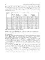
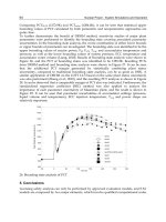
Fig. 2. Heated vertical pipe (IAEA benchmark 1). Effect of different heat transfer correlations,
calculated with APROS (Kurki 2010). Experimental data are from (Kirillov et. al., 2005)
APROS includes the four heat transfer correlations which can be used at supercritical
pressure flows - Dittus-Boelter, Bishop, Jackson-Hall and Watts-Chou. These correlations
Nuclear Power - System Simulations and Operation
146
were used for simulating a test case (Kirillov et. al., 2005), in which the steady-state heat
transfer behaviour in a heated vertical pipe was analysed for both upwards and downwards
flows (see Figure 2). The length of pipe was 4 m, the inner diameter was 1 cm, pressure at
outlet was 24.05 MPa, inlet temperature was 352 ºC and mass flux was 0.1178 kg/m
2
s. In
case of upwards flow the weak impairment of heat transfer occurs. It can be seen that the
Watts-Chou correlation is able to predict this quite well, while the Dittus-Boelter correlation
gives much too high values. The reason for too high values is that the heat capacity used in
Prandtl number increase strongly near the pseudo saturation state of 24 MPa. For
downward flow all of the correlations give sensible values – again Watts-Chou giving the
closest values. It should be kept in mind that this is only one example. It has been found that
any of available heat transfer correlations cannot predict the heat transfer impairments at all
conditions.
7. Wall friction
Estimation of two-phase flow wall friction in system codes is generally based on single-
phase friction factors, which are then corrected for the presence of two separate phases
using special two-phase multipliers. The wall friction factor for single phase flow is often
calculated using the Colebrook equation, which takes into account also the roughness of the
wall
⎥
⎥
⎦
⎤
⎢
⎢
⎣
⎡
−
H
D
ε
+
f
=
f
2
Re
18.71
2log1.74
1
colcol
, (12)
where
ε is the relative roughness of the flow channel wall.
Because at supercritical pressures the variations of the thermophysical properties as a
function of temperature may be very rapid, the properties near a heated wall – where the
skin friction takes place – may differ considerably from the bulk properties. The friction
factors can be corrected to take this into account by multiplying the factor by the ratio of a
property calculated at the wall temperature to property calculated at the bulk fluid
temperature. One of the friction correlations intended for supercritical pressure is the
correlation of Kirillov
()
0.4
b
w
2
b10kir
1.64Re1.82log
⎟
⎟
⎠
⎞
⎜
⎜
⎝
⎛
−
−
ρ
ρ
=f
(13)
This correlation has been formed by multiplying the friction factor correlation of Filonenko
(the first term) by a correction term based on the ratio of densities calculated at wall and
bulk temperatures respectively. However, this correlation is valid only for flows in smooth
pipes.
Since no wall friction correlation for supercritical-pressure flows in rough pipes is available
in the open literature, a pragmatic approach was taken in APROS to make it possible to
estimate the wall friction in such a situation: the friction factor obtained from the Colebrook
equation is simply multiplied by the same correction term that was used by Kirillov to
extend the applicability of the Filonenko correlation, thus the friction factor may be
calculated as
Thermal-Hydraulic Simulation of Supercritical-Water-Cooled Reactors
147
0.4
b
w
col
⎟
⎟
⎠
⎞
⎜
⎜
⎝
⎛
ρ
ρ
f=f
(14)
It is important to notice that this correlation is not based on any real data, and as such it
must not be used for any real-life purposes before it has been carefully validated against
experimental results. Thus, this form of the correlation serves only for preliminary
estimation of the effect of friction and is mainly intended for reference purposes (Kurki
2010).
8. Flow instabilities in heated channels
In simulating flows and heat transfer at the supercritical pressure region the possibility of
appearance of flow instabilities should be taken into account. Due to the rapid changes of
density and viscosity with changing temperature near the pseudocritical line, different types
of flow instabilities may occur. These instabilities are analogous to those related to boiling in
vertical pipes, and may be of the Ledinegg or the density-wave-oscillation (DWO) type.
Useful dimensionless parameters for defining the condition for stable or instable flows in
heated pipes are the sub-pseudo-critical and trans-pseudo-critical numbers proposed in
(Ambrosini & Sharabi 2006 and 2008).
The sub-pseudo-critical number describes the sub-cooling at the inlet of the heated pipe
section, and is calculated as
()
inpc
pc
pc
spc
N hh
c
β
=
p,
−
, (15)
while the trans-pseudo-critical number represents the proportion of heating power to mass
flux, and is defined as
pc
pc
in
tpc
N
p,
c
β
m
P
=
. (16)
With these two parameters the threshold for instabilities and the instable and stable flow
areas can be estimated.
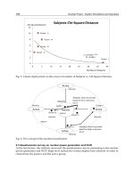
In the reference (Ambrosini & Sharabi, 2008) the stability boundaries of one particular
geometry as function of N
spc
and N
tpc
calculated with RELAP5 are shown. The calculated
values in the charts have been obtained by simulating the case where the flow under
supercritical pressure flows through a vertical uniformly heated circular pipe. At the inlet,
the constant singular pressure loss coefficient of K
in
=10.5 and at the outlet the coefficients of
K
out
= 0.0 and 3.0 were applied. The pressure at inlet and at outlet is kept constant, but the
heating rate is gradually increased, which results in a slowly increasing trans-pseudo-critical
number. The calculation was repeated with different sub-pseudo-critical numbers
corresponding to different inlet conditions. With a certain trans-pseudo-critical number, the
flow changes from stable to oscillating or experiences the flow excursion. In the charts the
instability threshold is presented when the amplifying parameter Zr has the value zero. The
instability values above the position, where the second derivative changes strongly,
represent the Ledinegg instabilities (N
spc
about 3). The values below N
spc
about 3 stand for
Nuclear Power - System Simulations and Operation
148
density instabilities. As an example, two calculation results obtained with APROS have been
shown in Figures 3 and 4. In Figure 3 the typical behavior of a DWO-type instability is
shown. The result representing the Ledinegg instability is presented in Figure 4.
Fig. 3. Example of oscillating type (density) instability (IAEA benchmark 2, N
spc
= 2.0, K
in
= 20,
K
out
= 20), Calculated with APROS
Fig. 4. Example of excursion type (Ledinegg) instability (N
spc
= 3.0, K
in
= 20, K
out
= 20),
Calculated with APROS
Thermal-Hydraulic Simulation of Supercritical-Water-Cooled Reactors
149
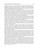
9. Simulation application – European concept of supercritical reactor
(HPLWR)
In an European collaboration project, the concept of a new reactor working under the
supercritical pressure has been developed (Schulenberg & al. 2008). This concept, called
High Performance Light Water Reactor (HPLWR), has a three-pass core (Fischer & al, 2009),
which was introduced to the design for preventing the formation of hot spots in the reactor
core. The coolant flows through the core three times in the radially separated evaporator,
super-heater 1 and super-heater 2 sections. Half of the feed water coming into the reactor
pressure vessel is directed upwards to the upper plenum in order to provide neutron
moderation for the reactor core and the other half flows to the downcomer, from where it
continues to the core coolant channels. Also for the moderator, a three-stage flow scheme is
applied.
For some preliminary accident analyses of the HPLWR safety concept, the APROS system
code was used (Kurki & Hänninen, 2010). The intention of calculation was on the other hand
make a typical large break LOCA analysis and also to verify the feasibility of the tentative
protection system. The accident which was analysed was a guillotine break of one of the
four steam lines. The accident was initiated by a 2 x 100 % break between the pressure vessel
outlet and the main steam line isolation valve. Decreasing pressure at the pressure vessel
outlet (
p
out
< 225 bar) initiates the reactor scram sequence and closure of the main steam line
isolation valves (MSIV). The time taken for fully closing the isolation valves is assumed to be
3.5 seconds. After the MSIV has been shut, the effective break size is 1 x 100 %.
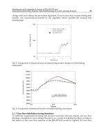
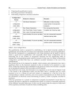
The calculation results (see Figure 5) suggested that with the assumed protection strategy
and with the used safety injection capacity the reactor core of the HPLWR can be kept
sufficiently cooled-down in the case of a large break LOCA caused by rupture of one of the
four main steam lines, using the designed safety systems.
Fig. 5. Results from the HPLWR LB-LOCA simulations: maximum flue cladding temperatures
(left) and pressures in different parts of the pressure vessel (right)
Nuclear Power - System Simulations and Operation
150
10. Conclusion
With modifications described in this paper, the six-equation flow model of the system code
APROS has been updated to work near and above the critical point. By using the concept of
pseudo saturation enthalpy the two-phase structure can be maintained. The developed
model for the forced mass transfer enables the numerically stable and fast transition from
pseudo-liquid to pseudo-gas and vice versa. The model includes a selection of friction and
heat transfer correlations that the user can choose to be used at supercritical pressures. One
deficiency is that at the moment there is not any heat transfer correlation which is able to
calculate the impairment of the heat transfer reliably. In simulating the supercritical flows in
heated pipes the instabilities due to large density changes is possible. In making simulations
with system codes or other simulation tools it is necessary to know the limits of these
instabilities. As an example of the HPLWR LOCA simulation proves the developed model
can be used for the safety analysis of supercritical-water-cooled reactors.
11. Nomenclature
A
area, flow area (m
2
)
β
volumetric coefficient of expansion
f friction factor
F friction (N/m
3
)
g
acceleration of gravitation (m/s
2
)
h enthalpy (J/kg)
m
mass flow (kg/s)
Nu Nusselt number
p
pressure (Pa)
Pr Prandtl number
q
heat flow/volume
Re Reynolds number
T
temperature (ºC or K)
t time (s)
u velocity (m/s)
V volume (m
3
)
x mass fraction
α
gas volume fraction
ρ
density (kg/m
3
)
Γ mass transfer (kg/s m
3
)
tΔ time step (s)
T temperature (C)
zΔ mesh spacing in flow direction (m)
Subscripts
b bulk
col Colebrook
g
gas
i interface
k phase k (either gas or liquid)
Thermal-Hydraulic Simulation of Supercritical-Water-Cooled Reactors
151
kir Kirillov
l liquid
lg evaporation, liquid to gas
p constant pressure
pc pseudo critical
sat saturation
w wall
Superscript
n new value
12. References
Ambrosini, W., and Sharabi, M., 2006, Dimensionless Parameters in Stability Analysis of
Heated Channels with Fluids at Supercritical Pressures, Proceedings of ICONE 14,
14th International Conference on Nuclear Engineering, July 17-20, 2006, Miami,
Florida USA.
Ambrosini, W., and Sharabi, M., 2008, Dimensionless Parameters in Stability Analysis of
Heated Channels with Fluids at Supercritical Pressures,
Nuclear Engineering and
Design 238 (2008) 1917–1929.
Bishop, A. A., Sandberg, R.O., Tong, L.S., Forced convection heat transfer to water near
critical temperatures and supercritical pressures, Report WCAP–5449,
Westinghouse Electrical Corporation, Atomic Power Division (1965).
Fischer, K., Schulenberg, T., Laurien, E., Design of a supercritical water-cooled reactor with a
three pass core arrangement. Nuclear Engineering and Design, 239 (2009), pp. 800-
812.
Hänninen, M. & Kurki, J. Simulation of flows at supercritical pressures with a two-fluid
code. NUTHOS-7: The 7th International Topical Meeting on Nuclear Reactor
Thermal Hydraulics, Operation and Safety, Seoul, Korea, October 5–9, 2008
Hänninen, M. and Ylijoki, J. The on-dimensional separate two-phase flow model of APROS.
Espoo 2008. VTT Tiedotteita – Research Notes.
Jackson, J.D., “A Semi-empirical model of turbulent convective heat transfer to fluids at
supercritical pressure, Proceedings of the 16th International Conference on Nuclear
Engineering, ICONE16 May 11–15, 2008, Orlando, Florida.
P. Kirillov and V. Grabezhnaya, Heat transfer at supercritical pressures and the onset of
deterioration, in Proceedings of ICONE14 (Jul 2006)
P. Kirillov, R. Pomet’ko, A. Smirnov, V. Grabezhnaia, I. Pioro, R. Duffey and H. Khartabil,
Experimental Study on Heat Transfer to Supercritical Water Flowing in 1- and 4-m-
Long Vertical Tubes, in Proceedings of GLOBAL 2005 (2005)
Kurki, J., Simulation of thermal hydraulics at supercritical pressures with APROS, Thesis for
the degree of Master of Science in Technology, Helsinki University of Technology,
Department of Engineering Physics and Mathematics, 2008.
Kurki, J. and Hänninen, M., Simulation of flows at supercritical pressures with a two-fluid
code, in Proceedings of the 8th International Topical Meeting on Nuclear Reactor
Thermal Hydraulics, Operation and Safety (NUTHOS-8) (October 2010
Kurki, J. and Seppälä M., Thermal Hydraulic Transient Analysis of the High Performance
Light Water Reactor Using APROS and SMABRE , 20th International Conference
Nuclear Power - System Simulations and Operation
152
on Structural Mechanics in Reactor Technology (SMiRT 20), Espoo, Finland, August
9 -14, 2009, SMiRT 20 – Division X, Paper 3164
J. Kurki and M. Hänninen, Simulation of a Large-Break Loss of Coolant Accident in the
High Performance Light Water Reactor, in Proceedings of IAEA Technical Meeting
on ’Heat Transfer, Thermal-Hydraulics and System Design for Supercritical Water
Cooled Reactors’ (July 2010)
Kurki, J., Computational modeling of a supercritical-Water-Cooled Reactor, Thesis for the
degree of Licentiate of Science in Technology, Aalto University, School of Science
and Technology, 2010.
Schulenberg, T., Starflinger, J., Heinecke, J., Three pass core design proposal for a high
performance light water reactor. Progress in Nuclear Energy, 50 (2008), pp. 526-531.
Watts, M. J., and Chou, C. T., Mixed Convection Heat Transfer to Supercritical Pressure
Water, Proceedings of the 7th International Heat Transfer Conference, vol. 3, 495 –
500 (1982)
9
Non-Linear Design Evaluation of
Class 1-3 Nuclear Power Piping
Lingfu Zeng, Lennart G. Jansson and Lars Dahlström
ÅF-Industry AB
Box 1551, SE-401 51 Göteborg,
Sweden
1. Introduction
A nuclear piping system which is found to be disqualified, i.e. overstressed, in design
evaluation using linear analysis software in accordance with ASME Boiler & Pressure Vessel
Code, Section III (ASME, 2009a), denoted as ASME III below for convenience, can still be
qualified if further design requirements can be satisfied in refined nonlinear finite element
analyses in which material plasticity and other non-linear conditions are taken into account.
For clarity, a design evaluation using such linear analysis software will throughout this
chapter be called a linear design evaluation, and a design evaluation involving a non-linear
finite element analysis a non-linear design evaluation.
The linear design evaluation according to ASME III is purely based on stress limits. Stresses in
piping components are first divided into membrane, bending and localized stresses for
formulation consistency with beam and/or shell structures. Thereafter, stresses are further
categorized into primary, secondary and peak stresses. The primary stresses are the “not
self-limiting” part of responses typically resulted from external forces such as dead-weight,
internal pressure, earthquake and so on, and they are important to avoid catastrophic failure
and to control plastic deformation. The secondary stresses refer to the “self-limiting” part of
responses resulted typically from thermal effects and gross structural/material discontinuities,
and they are responsible for eventually progressive/incremental deformation. The peak
stresses are the combined “peak” responses which are used to control fatigue failure. In
ASME III, design criteria are defined in terms of stress intensity or principal stresses. For
Class 1 piping systems, the criteria are defined by the stress intensity which is the largest
absolute value of the principal stress difference, or equivalently twice of the maximum shear
stress, and for Class 2 and 3 piping systems by the largest absolute value of the principal
stresses. In connection with the design-by-analysis approach, the linear design evaluation is
performed through comparing stress intensities of above-mentioned stress categories with
their allowable limits. Among software commercially available for performing such a linear
design evaluation, PIPESTRESS from DST Computer Services S.A. (DST, 2005) is widely
used in Sweden.
Furthermore, the linear design evaluation is conducted for each of the following load sets:
Design Condition and 4 so-called Service Limits of Level A, B, C and D. For different load
sets, different design criteria and requirements are used. Through defining various loads