Tài liệu bảo dưỡng Kawasaki 80zv 2 shop manual
Bạn đang xem bản rút gọn của tài liệu. Xem và tải ngay bản đầy đủ của tài liệu tại đây (15.92 MB, 549 trang )
mE Kawasaki
93209-00441
August 2011
SHOP MANUAL
WHEEL
LOADER
8O0ZV-2
General Information
Standard Measurement
Performance Check
Function & Structure
Check & Adjustment
Powered by CUMMINS
Serial No. 80C5-9001
QSC8.3 Engine
and up
Values for
93208-00501
August 2011
Foreword
To ensure good machine performance, reduce failures or problems, and prolong the service life of each component,
it is necessary to operate the machine as is directed in the Operator and Maintenance Manual.
To effectively diagnose and repair the machine, it is important to follow the guidelines laid out in this Shop Manual.
General Information
Function and structure
For the engine, refer to the engine Shop Manual provided by the engine manufacturer.
The purpose of this manual is to provide information on the product and the correct maintenance and repair methods. Please read this manual to ensure correct troubleshooting and good repair service.
This manual will be periodically reviewed and revised for more satisfactory content. If you have any opinion or
requests, please inform us.
Safety Symbols
An accident may occur if you disregard safety rules.
In this manual, several expressions are used according to levels of danger for inspection and repair work as shown
below. Read the work procedures and cautions described in this manual, and take preventive measures against
possible problems before starting service work.
4
DANGER
This danger symbol identifies special warnings or
procedures which, if not strictly observed, will result
in death or serious injury.
A WARNING
This warning symbol identifies special warnings or
procedures which, if not strictly observed, could result
in death or serious injury.
Á
CAUTION
This caution symbol identifies special instructions or
procedures which, if not strictly observed,
in minor or moderate injury.
may result
IMPORTANT
This
important
symbol
or procedures which,
identifies special
instructions
if not correctly followed, may
result in serious machine damage.
We cannot predict all possible accidents or incidents that may occur during service work. Therefore, an accident that
is not specifically mentioned in this manual may occur. To protect yourself from all accidents, be careful when doing
service work.
CONTENTS
BOZV-2 General Informaiion.........1112
....
1.111
....
1. ........
........---
How †o Use Manual............
co n2
......
2t
......
r ..
C22020
00-1
002000
. 064.
..
Hose band tightening torque ^.......
...
Liquid gasket and screw lock agent
00-17
.....c.cccccsssccsssssesstsnessssssistsersesersnstssasssssnssnnasssssssisssssstsasasasneseeeeeesceee, 00-18
Cautions regarding welding repair service............................
n1 11p rrEreerre
00-20
80ZV-2 Measurement for Performance Check
.....
Cautions on Safety...............................s.cccsoccccccrc
Standard Measurement Values for Performance Check.........................s
80ZV-2 Function & Structure Chassis Group. . . . . . . . . . . . .
Front CHASSIS
222220222
SH He
111
e
.
. s02 021111122181
re nrrr
tre
COAO1A......
SG...
..
12-2
7a1A........,,
12-2
Loading linkage pin. . . . . . . . . . .
cu 2n 2.,.01110 212211
teen
Hee
c.7.4.A.......
.
Fuel tank (S/N 9001~9128)...........................H212 1e
1e re
Rear CHASSIS
Fuel tank (S/N 9129~). . . . . . . . . . . .
Floor board moui[. . . . . . . . . . . . . .
há
022
set 2111112121121.
ng
ke
re erererrerrrereeeeeec
ơ.ơớ.ớớ.,ớ.a......
..
LOWer G©nfer pBỈn. . . . . . . . .
na.
c2
a
2t
1e
12-4
12-5
12-5
re
Hreereeseee 12-6
Upper certer pÏn. . . . . . . . . . c2
2
re
BC
12-1
te
12-7
12-8
12-8
HreHrarrsrseeee 12-8
.g.........
12-9
80ZV-2 Check & Adjustment Chassis Group .......cscscccccsssssessssssessssssesssssssssssassststisessssavec
tsssesssssstiseesssssssueeseeseecce 13-1
Linkage Pin
Center PIN
oo. œc-ưcưưc._ơ...ẶẶẶẶ....111.............
bò) 20980 0n...
........................................
Installing bearing COV@T. . . . . . . . . . . . . . . . .
ch
C110s83--00á)s09)).0uu
nu HH HH HH
22-1
POWEr LINE ốốốốốốốốốốốốốốốố
ố ốố cố
ốốố .ốốố................
22-2
Engine / Transmission "6
22-3
000)
=1
20
90001...
.á-
c1 22111 22111424 13K
.........................
22-3
.....................
22-4
ng
HH
C6160 A2008 Tố.
RadiatOr mOUTIE...................
cà
HT HT TH TH
“-4dđ4........
s00...
Radiator mOUTIE. . . . . . . . . . .-
2111111 K1
13-5
11111111 11 gi
Z12)0-0Ä1
TH
13-4
HH HH. KH TH HT TH HT vkc 13-4
AT“...
80ZV-2 Function & Structure Power GTOUD. . . . . . . . . . .
13-4
HH
Tàn
ưưi TH
HH
HH tr re 22-5
he................
HH HH HH HH
Propeller Shaft.....................................---Ặ SH
HH HH
HH HH. 11111112111
22-6
re. 22-7
2Ề1111111111271127112711117111217
HC. HH HH HH H20 Hàn rhàp 22-8
‘Second propeller shaft assembly.................................
cà HH HH HH HH
TH HT HH HH HH Tiện 22-9
Third propeller shaft ASSCMDLY ....... ccc
ccc
.ố
ố .<................
22-10
Axle ASSEMDIY ooo. ceceeeessseseneeessereceeeereeeteessaeecatsseeenensaeceaessaesasscasusseseseesseeusaeceaeseeseaesaeeesseparecsesseasaeaseesseasees 22-11
S902
.......ốốốốốốốốốốốốố.ốằẶộỒộ Ắ......aa...
Differential G@ar. . . . . . . . . . . . . . . . . . .
HH
Torque (s23 vn
02000
2
nh...
e0
TT
. ................
HH
1k
HH HH TH HH Hy
.......ee...UOố.
...
Measuring engine Oil PreSSUre
Propeller Shaft
1111211112 1110111 11111 TT
4..ÝÁÝÁÝ............
Limited Siip Differertial (Opfion)_. . . . . . . . . . . . . .
mu
TH T1
.................
ẽ....ẮẮ.ồ..........
Propeller Shaft phase
n“..
Axle nut tightening procedure:
.
nadd...
.........................................
Differential gear adjustment procedure
22-12
ườ 22-14
22-14
22-17
22-18
22-18
80ZV-2 Function & Structure Torque Converter and Transmission có..
.::‹-.
.
Torque Converter
32-1
.......................................
Torque converter structure
Power flow path
......................
Torque multiplication
............
Torque Converter Gear Pump .
Gear pump specifications
-
Transmission .................
Clutch combination
Shift lever position
Downshift button operation
..
Gear train and number of te fh. . . . . . . . . . . . . .
co nh n1
1
21112 Heo
32-5
Clutch specifications
Clutch Pack
....
Hydraulic System Diagram
oo... sccsssessesssssssesecsessecsnsssssssssisssussussssssecguesasissussnisstessessstsssssesstvesteeeseeeveesccees 32-14
Hydraulic Circuit Diagram........
c0. 212101112121
.....1.....
211 xe
.....
re
.....
Oil Flow ....
32-15
Clutch Solenoid Valve
ooo...
....
.. e.............
32-27
For forward/reverse and speed CIULCHES 22.0... cccccccssesessesesssecsesesecsecseseceseeceessesseevacevacavavasvassesscateseesavars 32-27
20000) 000...
13a354.........
TH tre
32-29
80ZV-2 Check & Adjustment Torque Converter and Transmission GroUp.............................
Q22 Hee
33-1
Clufch Oii PresSUre. . . . . . . . . . . . . . . . . .
cu SH.
Measuring Clutch oil Dr@SSUT€...........................
12 1110111011111 111111111 1111 TT
án
HH HH 1121111142 1 HH H11
80ZV-2 Function & Structure Hydraulic GrOUD. . . . . . . . . . . . . -
sát
TT TH
cư 33-2
HH HH HH TH HH
tàn 33-2
HT 121 8111112411112111 01T gen.
42-1
Flushing HydrauliC CirUif....................................
s1
nề H1 9111111111.1111 1211111411211 TT TH TH TH TH TT T0
ng 42-2
Purpose of flUshing,. . . . . . . . . . . . . . . . . -
---
1212221212011 11411111113 01111 1 131 1c HH
Cautions on Hydraulic Parts ReplaCementL........................
Hydraulic Circuit SYMDOIS
H210
2n H1 HH HH TH
TH HH
HH HH2
42-2
HH TH
42-3
““...............ee...Ả...
..
Hydraulic HIMOS ƯA...
PUMPS & MOOS
HC TH HH
ooo.
..........................
cece sseneeseeeaeeneseesseessessseesecoevsesaesaeseessssacsesaucssseessseesscsessucsuseucaesacsusssseaneseveceaeaase
2209 cố...
Operation Methods
l6 S0
..ốốốốốốốốốốốẽốố
ốốố .ốeốe^.............
s02)
I9. sou
ôn.
mẽ
ố
ốc
.ố ố.ố
hố.
ằe............
ố ốốốốeẮe.....
Directional control valve
CHECK VEIVE .............ố.ố.ố...........ƠỎ
Miscellaneous hydraulÍC symmbOlS..........................ccc
ch HH2412412111111 81 HH HH HH HH
ty
Hydraulic System OperafÏOn............................
HH
211 1111 c1 HH HH HH
.42-7
HH
.42-8
Hydraulic system operafion oufline.............................
Set cv 22111221 12 11H11 HH TH HH Hưun
.42-8
Layout of Hydraulic Unif8...................................
TL 2221211111 HH HT HH HH H141
01 ty
42-10
Hydraulic Tank
42-11
TT“...
ốằằ............
Hydraulic tank specificatiOns ...........................- e1
ke
42-11
Hydraulic oil level check .........................-sàn SH HH
He.
42-11
Hydraulic Tank (S/N 9001~9250)
42-12
Hydraulic Tank (S/N 9251~)
Hydraulic Pump
......................................
.......................
42-14
..................................c.c:
..42-16
Hydraulic pump Specifications An"...
. . .-. . . . . ố. 42-16
Hydraulic pump prinCÏDÏ©..............................
- - . -c c1 L1 2112111031612 111 TH tk Hà HT 11 HT
Hydraulic pump Wear Plate oo...
Hydraulic pump bushing lUubriCatiOn
HC TH TT kg
42-17
.....ẻ.ẻ................... 42-18
.........
..
HH
HH HH
HH1
1 HH
HH HH Ha 42-18
Hydraulic Cylinder.............
cv 2222101
.......
22110115.......
1011116 xererre
...
Đoom CyÏ nder. . . . . . . . . . . . . . . . . .
cv
Bucket ©ylinider. . . . . . . . . . . . . .
ch
vn
1H
011111211 2
Tá
42-19
110101222
01121111121
reree
2
se
re
42-19
42-19
Steering CylÏnder.............
1t .......
2v v22 121221 T1.......
H211 .......
112112212....-:eerrreeree
-cc 42-20
Hydraulic cvlinder specifications
Loading System. . . . . . . . . . . . . . . . .
............
ác LH
......
1012
......
21
......
s...
42-21
c2
42-22
2121 11 1
Reducing Valve (for Pilot Pressur©).............................
1111 n1
s1
Pilot Valve (S/N 9001~9208).,...................
c1
Pilot valve funcfion. . . . . . . . . . . . . . .
c2
2
Hee
1112110112221 2e
1211112
1211121
re
reerreeesee 42-24
tren
Pilot valve operation (modulated position)...............
11122111811
........
1E Hee
......-sccH
Pre-detent and detent magnet solenoid
42-23
42-27
42-27
......
Pilot Valve (S/N 9206~) ...................................
Multiple Control Valve (KML28/2T102)
testes
Muitiple control valve specifications ..
Multiple control valve main relief valve
.
Multiple control valve overload relief valve (with make-up FUNCTION) oo... scscessescsesceeseessecscessesseessssosseseseesee 42-38
Multiple control valve make-up VaIVE oo...
seecsessccssssescsssssssscsnsssavsssssecuasesanstesressesteateaterssevestcevessesceeseeceees 42-40
Multiple control valve buckef spo l. . . . . . . . . . . . . . -c:Multiple control valve DOOM §pOoI . . . . .
Adapter (OrifiCe). . . . . . . . . . . . . . .
HH,
Ride Control (OPT)
42-41
7:1 2222x222 E12 211 11211112112 10 EEerererrr
eo
42-43
11212121 1111
xe
42-46
..ccccescesssssssessessessesetssssseesssseesssssessssssussuessssesasssssusassnesesasesussusssssresseatsaveressesuscevscesensetseveeses 42-47
Ride control hydraulic Circuit
0...
cesseseessesssseesesseessssesecscaucsessessssessusenssssstesessetsusavessuusatasessussrcssesssseseeseees 42-47
Ride Control FUMCHION oo...
cececessesssestecesseestssessessnessssssseessseesssussscsvesessssusssesussussutsussussstiarsutestscersseseveescerseees 42-47
Ride control operafÏOn...........................
Ride control valve ASSOMDLY
tt
2222121121211 1121 TH x1
treo
42-48
o.
cescesesesssessessessessecscssesesscavssusessasssesecsrsarssssasssseareseasesesscsesseteseareeesseseseesees 42-50
-00000004................
42-53
K9 2060520
Accumulator (for ride confrol).....................
Steering System
2s 22t 2222212711211. 112.EEErrerrere
....
c2 22t 222112121121 1211011211111 Eereererrsaec
42-55
OrbitrolP specification........................
¿22t
Orbitrof® operation. . . . . . . . . . . . . . . . .
2 22112222210 T2 10
vu 221 222112211110
.t.seerereeree
TH H10
re
42-58
eeerreeerreerrree 42-59
Orbitrol® feed-back mechanism operation.....................
LH
H210 ...............
1222121
eeeeercee 42-61
Steering speed and flOW raf€ COI FOl. . . . . . . . . . . . .-.
2.
Hydraulic pump oil amount and st©e©rÏng ÍOrCe. . . . . . . . . . .
Orbit rotor operation prirtclpble.........................
.. .c. tt
.--c c1
Steering Valve (KVS25-A3.0/20)......................
HH
Steering valve operafiOn.................................
22 2 3211301 13 12121111151 111111111111 01 1 TT 110511111211 van crưy 42-62
2 22111111111 7 T11 T111
1111 111121211111111 11
H211
HH
1
HH1
H112
101116 1g, 42-62
1x11 HH
c1
ky 42-63
HH
rớc 42-64
c1 1 v22 2121112112121 11c 1111101111111
Steering plunger variable thrOtle. . . . . . . . . . . . . . .
Steering valve flow control plunger
cvay 42-66
St 2 n1 111011121112 2111110111111 0 HH
HH1
51 156 xEy 42-68
—..................
Steering valve main relief VaÏV©. . . . . . . . . . . . . . . .
L2. 1v 1v n2 1121111221111
01T
1 11g
42-69
rsyg 42-70
Steering valve overload relief ValV@...................
TL 2.12 221216111212 2110111
............
1111111111116.
. 42-72
Steering pilot circuit and its operafiOn.................
cuc. . t2 v22 222111211 .............
nh
1111112111 0g gu. ấy 42-74
Stop Valve
Siop valVe ÍUncfiOn. . . . . . . . . . . . . . . .
SH
T1 0111110111112 1 T1 HH
TT TH
H15
TH HH
Stop valve operation
Reducing Valve (for OrbitrolŸ)....................................ccccec ............................. 42-78
6C 00:0
õu...
.-........
E60
...
MS 6200/sỏ2021 0...
M9200/20101552
42-79
42-80
-âooo..-'"đ'đ..3đ'ÊÊđ5đ5-''.5.............. 42-80
3 U00...
Hydraulic line .................................--..--- TH E21 t1
....................
42-81
2211. E2 0012222150210 xe 42-82
Solenoid valve assermbly (1/2) ...............
2n t
H121 1211121211101
.........--.t
111111 gu
T H118
1121 ke 42-83
Solenoid valve assembly (2/2) ........................--.. nL t. ST n1 12111111111 121110111 11 1c
Efficient Loading Sys†em ................................. ch
HH HH1 T1,
21111111112 110111011 111111 11 TH 1T
H1 1k
HH
3/09150816-90e09)/3/208e0iu An"...
....
Mounting of the ELS valVe ......................... án
Mounting of the variable kicKOU†
0900806 0iis0)
E066
000A"...
.
0 20Noo. ri...
...
111012111111 11111 0 TT
2. St 1v 121112112121 5111T1 2 11 111101111111 11T
y 42-85
42-85
HH HH
thg 42-86
HH
ưyn 42-87
........
42-88
..........
42-89
Mounting 2Ä<8u s1...
Fan Motor Line
HH1
42-84
.ốỐoŨ.....
..............................
42-89
42-90
Reversing Fan Motor Line (OPT)
Reversing fan motor function
Hydraulic circuit (Reverse rotation)
Secondary Steering
Secondary steering operation
..............
Secondary steering motor and pump
...
80ZV-2 Check & Adjustment Hydraulic Group...
Loading/Steering Circuit Relief Valve/Ride Control Circuit Reducing Valvé (OPT)
.....cccecccsccsessssesesesssesessersees 43-2
Loading circuit relief valve setting pressures
....
Cylinder natural Orift
csscseescsecssseessseesssssesessnssesssessssscesssesssnessssussssessessussssasesssuesssusssasesssstustassavessivseessecee
0...
Stop Valve ...................
Stop valve adjustment procedure
..
80ZV-2 Function & Structure Brake Group................
c1 .......
1212 re
..........Brake System Outline.....
Service brake ..
Parking brake ..
Brake Units Layout
Unloader Valve ...
Unloader valve operation
Valve Unit .
Accumulator
IN-LiM@ Filter
Brake VAIVE
eee
eecseceseessescsecssesssucssecsssssssscasscnasesssecsasesuscssasssscssavessessussssusesasssiisasavessusssssssitessstesitesseeessecces
.7.Ắ.1.AA..............
aaaaẫäậa
cose
Parking Brake oo... ce cece
.... .......................
Parking brake operafiOn...................................
chinh
HH HH
1
52-18
re
52-19
Parking brake solenoid ValVe...................................
s21
H111 1 11211111111111211 115102 T1 TE TT
gư 52-20
Parking Brake Manual ReleaSe ..................... LH
HH 0010111001 4 HH HH HH nang TH HH
41113111511 re 52-21
Parking Brake Spring Chamberr ........................... ----- c2t S222 11121211211114 1110101 H11 HH TH HT HH H11
Brake Circuit Check ValVe. . . . . . . . . . . . .-.
ch
HH H011
Pressure Sensor (for stop lamp and declUfCh)..........................
HH
1 1111111111111 111 T12
rên 52-24
--. S: St nh T212 11131111101 1 T1 HH HH
HH
Pressure sensor (for declUiCh) ........................ c8
0 TH HH HH TH
BS
000i s96
o0
52-23
giờ
HH
niên 52-25
0n...
.... 3.
80ZV-2 Check & Adjustment Brake GrOUp. . . . . . . . . . .
Brake Circuit Oil PreSSUTe............................
Tà
án.
.2 H121 11111110 1111111121 121141 1 11 HH
52-25
ngờ 53-1
21111 1x41 15111 171 111111111 12811110111 1111201111
Hee 00 028-200...
52-25
ườc 53-2
..........
53-2
Brake valve Oil PreSSUre oo... ceceeecseessereeseeseeseesescescessesaessessssecsaesaseascsecasscasesccsucuevscssccscsuassssusensansausseverseareces 53-4
S@rviCe cố
ốc cố cố cố ốố.ốốốốeốe...........
Service brake performance CheCK ........................-
c2
HH0 111111 111111111 1111 1111111111421 1101110101111 T111 g1 53-6
Service brake friction plate wear meaSL€ITTIÍ......................
Cautions on installing brake diSCS tu nn
Beb ca...
53-6
HH
HH21111001
01110
HH
53-7
.............ddẢ..
53-8
ỞỎI..—Ý®Ý.........
53-9
Parking brake performance check. . . . . . . . . . . . . . . . s01
1111 18131112111111111.T1 1111111511111 1T
Parking brake clearance adjUSỈm@Tn[...................... c1
KH HH HH TH HH1
11T KH
53-9
Hư
53-10
80ZV-2 Function & Structure Electrical GrOUp...............................-.
n2
HH nh HH2 1111111111114 01 HH HH
ưy 62-1
How to Use Electrical Wiring Diagram............................
óc 2c. 211222 1112111111 11901111101 110 TH Hàn
TH
Lư
Utilisation des schémas des câblages électriques (FRANCAIS) .................... c2
Verwendung des elektrischen Schaltplans (DEUTSCH) .................... L1.
HH
HH HH HH
62-2
uưên 62-3
H110
rên 62-4
Modalità di utilizzo dello schema dei collegamenti elettrici ([TALIANO)}...............
L2 HH2
ty 62-5
Cómo utilizar un Diagrama de Alambrado Eléctrico (ESPANOL),............................/2.222 1202022212121 11112111212. 62-6
Como Utilizar o Diagrama de LigacõØes Eléctricas (PORTUGUÊS)
Electrical Cable Color Codes
mm"...
ốc
cố
ố
ố
..............................22
222221 TT
yecrrry 62-7
e...........
62-8
Sau c00e0 063 /0016Ố“..........e.............
62-9
ESI o0“...
—................................................
SP...
ẻ.e..........................
62-10
62-11
62-11
Voltage relay................................Q ng,
Power Generating/Charging Circuit..............
c1 22112 1n
.......
n2
.......
rreereree
......
eesee 62-22
l0
ECM
0 .77.ẠẢA.....
‹....
(Engine Controller)..........................
Function of ECM
ch 2v H1
1 H221
1t
re
re
.....................................,
Connection diagram. . . . . . . . . . . . . . .
62-22
62-23
62-23
uc,
11211 ke
Monitor lamp test
re
na.
62-23
62-24
Failure diagnosis .........csecssesscsessesssecsessntesesssecsssseesssssrsessustsesussssesevsasessessuetssstsessatsrensassassassettesiseeseeetecseees
62-25
Quantum fault code information 2. .
Accelerator pedal. . . . . . . . . . . . . . .
ec
ch.
eescessscsessecsessessssssusssevessssesavesssssasssusssussusssesssssassssssiseseeceeeeeseeescesee 62-28
0212221211221 1111111 eo
Transmission Control Circuit and Monitor Circuit. . . . . . . . . . . . . .sMachine control unit (MCU)
Machine control unit (MCU) function. . . . . . . . . . . . . .
Adjustable declutch preset switCh. . . . . . . . . . . . . . .
instrument Panel and Switch
Instrument panel
....
Instrument panel rear surface
Gauge circuit ...
Fuel level sensor ....
2212211
62-37
..
Machine control unit (MCU) connection diagram
Monitoring system
sec x11
62-34
........ccccccccssscesssssesssssessessesstessesestasesssssesesstestecseseeseeceesee 62-39
ác t2
HH HH1
1212
21021
1e
62-41
62-46
MODM
3.
........................................
MODM FUN CHION 00...
00120190510
ốc
62-61
ốốốố.ốốố.ốố.ố............ố.ố... 62-61
“““......e.e.............
62-61
I092/10520/ 023162... ......................
62-64
Replacement Monitor mm...
.ốe.............
62-68
ốố ố ẻ...............
62-74
Fault Log Monitor
010049111010) sào...
.... e4...
Parameter Setting MOnitOr. . . . . . . . . . . . . . . .-.
le 210e-i0si= 00 0 lv:
-. . 1 S121 vn
H1 H1 H1 H1 HT HH
TH TH TH
TH
62-81
Tà kg
dc 62-85
0n .......ố...............
Electrical Deteni CÏrCUl . . . . . . . . . . . . . .
HH.
1111 1 KH HH
HT HH TH
TL
11111181110 TH TH
62-94
Hàn 62-100
E00 001520- BA"...
.ố e.....................
62-100
B066
62-101
03 sẽ...
Lift kickout & loWer kiCkOUIL. . . . . . . . . . . . . .
..^.....Ả€ŸỀÝ.................
..- ng.
c5...
BESiS6-v sào
hố
Preset height adjustment
Bo
mm...
Mos-ei.2
002
........................
ằe........
"...
.ốố
ố ốố
gaaHaẢỶẢ...
....................5-------3:31.......
0n...
ốc
ốc cố ố.ee.............
Caution for diode check me†hod............................
ch HH1
Surge voltage and surge suppression dÍOd@S
Cabin.................................. HT
GlASS ............................ Ăn
ch
HH TH HT TH HH TH
nàn. nà
1 HH
TH
HH TH TH
6...
.......
62-106
62-106
62-107
62-108
1110111 Hư. 62-108
TH nh
TT
HT
HH HH1 11011 101 net Hi, 72-1
KT TT TH TT
HT T HT HH
T171 7111 111111111121 ce 72-2
1771112271111 1ETEET1111111.1 1C Ece 72-3
02010111 ..........................
Wiper MOTO
62-104
...........................
HH HH HH HH0 1021111 11 1 010 Hư. 62-110
80ZV-2 Function & Structure Operator Station GTrOUD. . . . . . . . . . .
MU
11 11.1 10 1111111111111. E111E1111.111112111 1c tre 62-102
.................................
72-6
72-7
............................
72-9
Steering and Transmission Shift Lever ..........ốốốe..............
72-10
I5
....................................................
P2I00un I6
<<Ở|ÖŒA.............
72-11
72-12
Air Conditioner
ốc
ốc
ốc
Denso air condifioner componenfs.....................................
-ccccscy
Denso air conditioner struc†ure....................................--.csccrz
Function of cooling mechanism
................................
Cooling Circuit: oo. eeeeceeesescseesesesesescevessseessteeneens
Electrical circuifL.................................-ccccccccccse,
Air conditioner functions of components
..
Charge of refrigerant.........................
Air conditioner troubleshooting
......
80ZV-2 Check & Adjustment Operator Station Group
Air Conditioner............................
Adjustment of lubricating oil quantity when components of air conditioner are replaced............................. 73-2
Adjustment of air gap (between hub and rotor) in compressor magnetic ClUtCH ........eccscececseceececsesesevesessese 73-5
Compressor V-belt adjustment .
Parts to be replaced periodically .
80ZV-2 Drawing & Diagrams
Axle Assembly
...
..
Torque Converter and Transmission
.
Hydraulic & Brake Circuit
Brake Circuit ..
Electrical Wiring Diagram (1/3) (S/N 9001~9038) oo... cscsscsessesessesessescsssscerssnsassnsacavsscessacaransavsusuessssesavaseaversesee 92-6
Electrical Wiring Diagram (2/3) (S/N 9001~9038)............
Q.20............
2212 n1 1101
..........xen re 92-7
Electrical Wiring Diagram (3/3) (S/N 9001~9038)........
Q.0 Q.2
.........
2.22 2 11211121
.........
2e re reeree
.. 92-8
Electrical Wiring Diagram (1/3) (S/N 9039~9100)......................
0 Q.00 HT HH H111
5111
EHenenrey 92-9
Electrical Wiring Diagram (2/3) (S/N 9039~9100)............
Q.22, ...........
1022122221111
.........eerrsere re
92-10
Electrical Wiring Diagram (3/3) (S/N 9039~9100)..........
S20..........
2212 1012
.......-.
rrererrse 92-11
Electrical Wiring Diagram (1/3) (S/N 9101~9200).....................
.-Q
HH 211 teen
92-12
Electrical Wiring Diagram (2/3) (S/N 9101~9200) ..........L0.
..........
Q.2 0002121211112
..........
se
.Electrical Wiring Diagram (3/3) (S/N 9101~9200)..........
2n ..........
2121121110111 .........
Hee
Electrical Wiring Diagram (1/3) (S/N 9201~) ......................
St n2. HH
HH ng
HH HT
HE
92-13
92-14
rsec 92-15
Electrical Wiring Diagram (2/3) (S/N 9201~)..........
.2221022121
........
21111012111 Hee
.....Q..
re .
nu
92-16
Electrical Wiring Diagram (3/3) (S/N 9201~) ..........................
92-17
Electrical Wiring Diagram............................
Way of looking at connecfOrs..........................
-cc.
TH
HH
H121 115111711
8T
HHHHenHnec
2122 1111121111 2111 1111 0111111111151
cu
21122121
T
se
xen
nee 92-18
re
92-18
Electrical Wiring Diagram (CAB) .................... cv...
HH4
110111 11111 1101 HH
TT
Tx các
T Ty
Electrical Wiring Diagram (Cabin Air Conditioner)..............
--st ch LH HH1 HT............
HH TH HH gườc
Electrical Circuit Diagram (Cabin Air Conditioner}........................ cà
Elecirical Connection Diagram (1/2) (S/N 9001~9100)..................
Q0
HH
c2 HH H411 110 k8
ngư
HH
ky
Electrical Connection Diagram (2/2) (S/N 9001~9100)....................
LG. S222 1 T0 HH ........--HH HT
Hy
Electrical Connection Diagram
(1/2) (S/N 9101~9200)
Electrical Connection Diagram (2/2) (S/N 9101~9200)
Electrical Connection Diagram (1/2} (S/N 9201~)
...........
.QQ.L.L LH
HH HT HH H11 1xx..
gan
...........
....
..
Electrical Connection Diagram (2/2) (S/N 9201~) ......
Equipment Operation Table (Cabin Air Condiftioner)...................
Electrical Equipment Layout
Electrical Equipment Layouf (K-L@V@T) Q..............
Outline of MODM
MODM:
uc H21
s1
HH 1
HH
HH
(Machine Operation Diagnostic Module) Operafion................................. Lee
rêu
92-47
Input/Output Monitor - Input/Output Signal Correspondence Table...............................-QL cTnnnnecey 92-56
00-1
80ZV-2 General Information
80ZV-2
General
Information
How to Use Manual... ceccesseseeserssesssesssceenevees 00-2
5®
cece ects ceescesesecstsssescerssvavsrtassevaveeeace 00-4
00-2
80ZV-2 General Information
How to Use Manual
How to Use
Manual
Safety precautions
Do not start to work in an enclosed area if adequate
ventilation is not provided.
The most important point in providing repair service is
safety. To ensure safety, observe the general cautions
described below.
To remove a heavy unit (20 kg (40 Ibs} or more), be
- This manual is intended for
equipped service technicians.
properly
trained
- Any work on the machine must be performed
trained personnel only.
and
by the
Carefully read this manual to thoroughly understand
the operation method before you operate or repair
the machine.
sure to use a crane or other lifting device.
Just after stopping operation, be careful not to
directly touch a hot component. You may get burned.
Contact tire manufacturer's
vicing and changing.
local dealer for tire ser-
Always store the tools in good
them properly.
Keep the work
ately.
area clean. Clean
condition, and use
up spills immedi-
- Be sure to wear appropriate clothes and protectors,
such as safety boots, hard hat and goggles.
Avoid the use of flammable solvents and cleaners.
- Place the machine on level and solid ground, and
place chocks against the wheels to prevent movement.
When working outdoors keep work areas, ladders,
steps, decks and work platforms clear of snow, ice,
and mud.
- Remove
Use safe work platforms to reach higher areas of the
machine.
the cable from
the service work,
and
the battery
attach
ATE!" tag to the steering wheel.
a "DO
before
NOT
starting
OPER-
IMPORTANT
lf a battery terminal
is removed
from
a machine
in
less than 30 seconds after the key is put into the
“OFF” position, it can corrupt the ECM program,
which can disable the engine. Always wait 1 full
minute to be sure to be past this “write to memory
function” prior to removing battery terminals.
- Be sure to release the internal pressure before you
remove a pipe, such as the hydraulic oil, air, or
engine coolant pipe.
- Be sure to apply the articulation stopper before starting work.
- While supporting the botiom of the chassis using a
jack, be sure to support the chassis using the blocks.
- When the boom or bucket is raised or when
a unit is
lifted by a crane, be sure to place a stand or ade-
quate cribbing under the unit to prevent unexpected
dropping.
Any technician that operates a refrigerant recovery
and recycling machine must first be certified through
an EPA approved testing program.
More information is available at http:/Avww.epa.gov/
ozone/title6/608/technicians/608certs.html.
00-3
80ZV-2 General Information
How to Use Manual
Symbols
For safe and effective service work, the following sym-
bols are
manual.
used
for notes
and
Symbol
useful
information
ltem
Description
Reference
Shows the condition or procedure that will be useful
¬"
.
E
or efficient in doing service work.
.
Weight
so
Shows the weight of a part or unit. The weight
should be considered in selecting wire rope or cable
_
.
for slinging work or determining the working posture.
Tightening | Shows the tightening torque ofa section that should
torque
4 j ^=
tay
a
in this
4
Coating
Oil or
waier
supply
Drainage
9®
|be carefully tightened during assembly work.
Shows the type of coating or adhesive and the coat¡ng section.
,
Shows the oil or water supply port and the refill
amount.
Shows the oil or water drain port and the drain
lamount.
IMPORTANT
If the specified conditions are not satisfied or the specified procedure is not
observed, there is.a strong possibility that the product will be damaged or the performance of the product will be reduced.
The message shows the preventive measures.
Abbreviation
To save space, abbreviations are used in sentences. To understand the contents of this manual, refer to the follow-
ing abbreviation list. Additional abbreviations are listed on page 92-20.
...
..
...
...
Engine
Torque converter
Transmission
Solenoid valve
Switch
... Front or Forward
Auto/Manual
Battery
Rear or Reverse
RH
LH
"
Right hand side
... Left hand side
.High
3rd
4th
....Ground
ELS.
MIC .
.
Low
min†.
-Option
Assembly
1st speed
..2nd speed
MODM
3rd speed
4th speed
.Machine
.RPM
-Efficient loading system
.Machine
operation
nostic module
MCU........... Machine control unit
diag-
00-4
80ZV-2 General Information
Outline
Outline
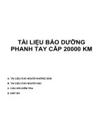
Layout of main components
L
U
/
16 (S/N 9101~)
17
10
15
11
13
24
16 (S/N 9001~9100)
ONAAARONA
KB0V2U00001
Engine assembly (Cummins QSC8.3)
. Transmission/Torque converter assy
Hydraulic pump
Multiple (loader) control valve
. Steering valve
Pilot vaive (for loading)
. Transmission control valve
. Air cleaner
9.
10.
11.
12.
13.
14.
185.
16.
Muffler
Radiator
Front axle assembly
Rear axle assembly
2nd propeller shaft
3rd propeller shaft
Hydraulic oil cooler (air-to-oil type}
T/C oil cooler
17. Air charge cooler
18. Parking brake
19. Fan motor
20. Brake valve
21. Accumulator
22. Combination valve
23. Unloader valve
24, Fan
00-5
80ZV-2 General Information
Outline
Inspection and maintenance table
Refer to Operation & Maintenance
nance procedures.
Manual for mainte-
IMPORTANT
Severe
nance.
application
require
more
frequent
mainte-
Severe conditions include heavy dust, extremely
abrasive material, caustic chemicals, extremely wet
Conditions or abnormally hot or cold ambient temperatures.
A:
Operating hours
Item for check
=
Section
First time replacement or cleaning only
When
50 | 250 | 500 | 1000 | 2000 | Required
Check Engine Coolant Level
Check Warning Lamps
Check Exhaust Gas
Drain Water and Sediment from Fuel Filter
Check Fuel Level
Check Drive Belt
Check Crankcase Breather Tube
Check Air Intake System
Check Cooling Fan
Engine
©jO|O|O|O|O|lG|Olclo
Check Engine Oil Level
Drain Water and Sediment from Fuel Tank
Replace DCA4 Coolant Filter Cartridge
Replace Engine Oil and Oil Filfer Cartridge
Replace Fuel Filter Cartridges
Inspect Automatic Belt Tensioner Pulley
Check and Adjust Valve Lash Clearance
oO
Clean Fuel Tank
Check Vibration Damper
Clean or Replace Air Cleaner Element
©
©
Clean Radiator / Air cooler / Hydraulic oil cooler Fins
Clean or Replace Air Cleaner Element
Replace Coolant
Note
*1 applies to machines from S/N 9201 and up.
Refer to Operation & Maintenance Manual for details.
Check Transmission Oil Level
Transmission & | Replace Transmission Oil Filter Cartridge
Torque Converter
Replace Transmission Oil
Clean or Replace Transmission Breather
After six cleanings or once a year
Every 2 years or 3000 hours
©
O
00-6
80ZV-2 General
Outline
Information
“A: First time replacement or cleaning only
Section
Item for check
Check Tire for Damage, Air and Tread Depth
. Operating hours
@
Greasing (Axle support)
oO
Check Tire Air Pressure
oO
OJO;O}O
Check Differentia! Gear Oil
Check Planetary Gear Oil
Axie system
Greasing (Pillow block bearing unit)
Check Tightness of Wheel Bolts
Greasing (2nd Propeller Shaft Spline)
oO
Replace Differential Gear Oil
oO
Replace Planetary Gear Oil
oO
Greasing (2nd Propeller Shaft)
Every 12000 hours
CQ
Greasing (3rd Propeller Shaft)
Every 12000 hours
©
Check Steering Wheet Operation
oO
Steering system | Greasing (Steering Cylinder)
œ
Clean Filter for Orbitrol®
Brake system
When
10 | 50 | 250 | 500 | 1000 | 2000 | Required
A
Check Service Brake Operation
oO
Check Parking Brake Operation
O
Adjust Parking Brake Lining
O
oO
Check Service Brake Disk Wear
oO
O
Check Brake Accumulator
Clean Filter for Brake Line
Check Hydraulic Oil Level
A
œ
Greasing
œ
Replace Hydraulic Oil Return Filter
A
Replace Hydraulic Oil, Clean Filter
œ
Rteplace Filter in the Hydraulic Tank Cap (S/N 9001~9250)
Replace Filter in the Hydraulic Tank Breather Valve (S/N 9251~)
Chassis
oO
oO
Loading system
Oo
O
Replace Bucket Teeth (option)
œ
Replace Cutting Edge
Oo
Adjust and Check Rear View Mirrors
oO
ROPS (Roll Over Protective Structure) Cab
oO
Greasing (Center Pin)
Check Ride Control Accumulator (option)
@
Oo
Check and/or Replace Seat Belt
O
Check Windshield Washer Fluid
oO
00-7
802V-2 General Information
Outline
A:
Section
Operating hours
Check Horn Operation
Electrical
system
Check Back-up Alarm Operation
Check Wiring Harnesses
50
250
500
1000
2000
©Ø!O|OIO
°
Item for check
Check Monitor Pane! Operation
First time replacement or cleaning only
Check Battery Electrolyte Level
Check or Replace Fuses
Check and Adjust Air Conditioner Belt
Clean Air Conditioner and Heater Filter Element
Air Conditioner
Check Air Conditioner Refrigerant
Replace Air Conditioner Fitter Elements
©
Clean Air Conditioner Condenser
Replace Air Conditioner Receiver Dryer
Others
Walk-Around Inspection
Every 3 years or 6000 hours
|
|
(
When
Required
00-8
80ZV-2 General Information
Outline
Recommended
lubricants
Refill capacity
(Approximate)
Kind of Ol
Engine
33 liter
.
,
Engine oil
(CH4 or CI4)
Transmission
35 liter
ine
oj
Engine on (co) or
#4
x3
.
,
.
Hydraulic tank
85 liter
Differential &
Front: 54 liter
Rear: 59 liter
Engine oil (CD)
Fuel tank
.
290 liter
.
Diesel fuel
Planetary
Ambient Temperature (°C)
+30
-20
0
10
20
30
40
Change Interval
SAE10W-30
500
AE10W
ATF
I8O VGB2
;
Engine
1,000
Iso yeas
2,000
gil SAE40or| SAE30
ASTM D975 Nd.4,
lASTM
(Hours)
x2
SRE1BW-40
Hydraulic oil
.
-10
D978
2,000
No.2
;
daily
Note: *1 shows "Hydraulic tank oil capacity at level gauge center.”
Engine
Use oil that meets engine oil classification API CH4, Cl4 or CG4.
+2. Change engine oil every 250 hours if CG4 is used.
Engine oil drain intervais need to be reduced by 50 % when fuel sulfur content exceeds
0.6%.
Transmission
Use engine oil classification AP| CD or A.T.F. (Auto Transmission Fluid).
Never mix engine oil and A.T.F.
Hydraulic System
Use industrial-type hydraulic oils which are certified by suppliers having anti-wear, antifoam, anti-rust and anti-oxidation additive properties for heavy duty use. Use of the wrong
viscosity of oil can cause improper operation of hydraulic functions or premature pump fail-
ure.
+3. In a case that fire-resistant fluid is used in the hydraulic circuit, some hydraulic equipment, such as pumps and/or fan motor, must be replaced periodically.
Warning: When operating in cold ambient temperatures (15 °C or colder) ISO VG32 or
equivalent hydraulic oil use is recommended. When changing over to cold climate
hydraulic oil (i.e. from thicker !SO VG46 to thinner ISO VG32), brake system bleeding
at each wheel hub will be required to remove thicker oil and prevent delayed reaction
of brake application and release.
Differential &
Use class API CD engine oil with 5 % “Antichatter" additive or friction modifier.
Lubricating Grease
Use multipurpose-type EP/MOLY grease for most applications.
NLGI NO.2 grease is suitable for most temperatures.
NLGI NO.1 or NO.0 grease for extremely low temperature.
Planetary
Use lithium base grease for universal joints and a propeller shaft spline.
00-9
80ZV-2 General Information
Outline
Diesel Fuel
Requirements for diesel fuet
Specifications
Flash Point
°C.
% vol.
Distillation Temperature
Cetane Number
38
52
°C
0.05
0.05
max.
288
338
min.
1.3
1.9
max.
24
4.1
0.01
0.01
0.50
0.50
max
90% vol.
recovered
Kinematic Viscosity mm?/s at 40°C
Sulfur % mass
Grade No.2-D
min.
Water and Sediment
Ash % mass
Grade No.1-D
max.
max.
min.
Carbon residue on 10% distillation residue % mass
max.
40
40
0.15
0.35
00-10
80ZV-2 General Information
Outline
Coolant
Coolant specification
The
machine
is originally filled with Long
Life Coolant
(non-Amin type ethylene glycol) which need
replaced for the first two years or 3,000 hours.
not
be
Do not use Amin type Long Life Coolant in cooling system, It may cause a corrosion against radiator or heater
core.
If standard antifreeze (not Long Life Coolant) is used for
the replacement,
months.
it
should
be
replaced
every
Recommended
mixture of antifreeze
six
(S/N 9001~9100)
Expected minimum
ambient temperature
-35°C | -30°C | -25°C | -20°C | -15°C
|(-31°F) | (-22°F) | (-13°F) | (-4°F) |
(B°F)
(le) | 296 | 328 | 359 | 398 | 422
Pure Water | (gay | (7.8) | (8.7) | @5) | (105) | (11.2)
Antitreese | tien | 334 | 302 | 271 | 234 | 208
(aj | (89) | (80) | Œ2) | (2) | (85)
Mixture Ratio (%)
53
48
43
38
33
(S/N 9101~)
Expected minimum
-35°C | -30°C | -25°C | -20°C | -15°C
ambiént temperature | (-31°F) | (-22°F) | (-13°F) | (-4°F) | (5°F)
(liter)
14.6
16.1
17.7
19.2
20.8
53
48
43
38
33
antifreeze
in the
Pure Water | ‘gals | (3.9) | (67) | 47) | (61) | @5)
.
(le) | 184 | 149 | 133 | 118 | 102
Antifreeze | (gay | (4.3) | (39) | (35) | @1) | (27)
Mixture Ratio (%)
- Too
much
cause engine overheating.
coolant
mixture
may
Keep 33 % antifreeze mixture (same as the mixture
for a minimum ambient temperature of -15°C (5°F)) if
the engine overheats in a high ambient temperature.
- Do not use hard water or water with high levels of
calcium and magnesium
ions as the coolant water.
IMPORTANT
Do
not
mix
different
brands
of antifreeze
because
they each contain special additives.
Careless mixing often diminishes the effect of these
additives that causes
leakage.
the packing
damage
or water