Biofuel''''s Engineering Process Technology Part 9 pot
Bạn đang xem bản rút gọn của tài liệu. Xem và tải ngay bản đầy đủ của tài liệu tại đây (924.68 KB, 40 trang )
Rheological Characterization of Bio-Oils from Pilot Scale Microwave Assisted Pyrolysis
311
indicates that they are easy to handle and processing; however, viscosity is not the only
factor deciding the application of bio-oil. Therefore, other factors should be investigated to
assess the suitability of these bio-oils.
5. Acknowledgements
This research was supported by funding from the Agricultural Experiment Station and
North Central Sun Grant Center at South Dakota State University through a grant provided
by the US Department of Transportation, Office of the Secretary, Grant No.DTOS59-07-G-
00054. Also, Bio-oils provided by Dr. Roger Ruan, University of Minnesota for conducting
this study was greatly appreciated.
6. References
Anto, L. P., & Thomas, S. (2009). Production of bio-oil from pyrolysis of bagasse.
Proceedings of International Conference on Energy and Environment ISSN: 2070-
3740, pp 558–559, March 19-21, 2009.
Asadullah, M., Rahman, M. A., Ali, M. M., Rahman, M. S., Motin, M. A., Sultan, M. B., &
Alam, M. R. (2007). Production of bio-oil from fixed bed pyrolysis of bagasse. Fuel
86, 2514–2520, 0016-2361
Asadullah, M., Rahman, M. A., Ali, M. M., Motin, M. A., Sultan, M. B., Alam, M. R., &
Rahman, M. S. (2008). Jute stick pyrolysis for bio-oil production in fluidized bed
reactor. Bioresource Technology 99, 44–50, 0960-8524
Ba, T., Chaala, A ., Garcia-Perez, M., Rodrigue, D., & Roy, C. (2004). Colloidal properties of
bio-oils obtained by vacuum pyrolysis of softwood bark. Characterization of water-
soluble and water-insoluble fractions. Energy & Fuels 18, 704–712, 0887-0624
Bhattacharya, P., Steele, P. H., Hassan, E. M., Mitchell, B., Ingram, L., & Pittman Jr, C. U.
(2009). Wood/plastic copyrolysis in an auger reactor: Chemical and physical
analysis of the products. Fuel 88, 1251–1260, 0016-2361
Blaschek, H. P., & Ezeji, T. C. (2010). Science of Alternative Feedstocks.
/>l%20report%20-%20ch%207.pdf. Accessed on April 15, 2010
Boateng, A. A., Daugaard, D. E., Goldberg, N. M., & Hicks, K. B. (2007). Bench-scale
fluidized-bed pyrolysis of switchgrass for bio-oil production. Industrial &
Engineering Chemistry Research 46, 1891–1897, 0888-5885
Boateng, A. A., Mullen, C. A., Goldberg, N. M., Hicks, K. B., McMahan, C. M., Whalen, M.
C., & Cornish K. (2009). Energy-dense liquid fuel intermediates by pyrolysis of
guayule (Parthenium argentatum) shrub and bagasse. Fuel 88, 2207–2215, 0016-2361
Boucher, M. E., Chaala, A., & Roy, C. (2000a). Bio-oils obtained by vacuum pyrolysis of
softwood bark as a liquid fuel for gas turbines. Part I: Properties of bio-oil and its
blends with methanol and a pyrolytic aqueous phase. Biomass and Bioenergy 19,
337–350, 0961-9534
Boucher, M. E., Chaala, A., Pakdel, H., & Roy, C. (2000b). Bio-oils obtained by vacuum
pyrolysis of softwood bark as a liquid fuel for gas turbines. Part II: Stability and
ageing of bio-oil and its blends with methanol and a pyrolytic aqueous phase.
Biomass and Bioenergy 19, 351–361, 0961-9534
Biofuel's Engineering Process Technology
312
Bridgewater, A. V. (1999). Principle and practice of biomass pyrolysis process for liquid.
Journal of Analytical and Applied Pyrolysis 51, 3–22, 0165-2370
Bridgwater, A. V. (2003). Renewable fuels and chemicals by thermal processing of biomass.
Chemical Engineering Journal 91, 87–102, 1385-8947
Bridgwater, A. V. (2004). Biomass fast pyrolysis. Thermal Science 8(2), 21–49, 0354-9836
Calabria, R., Chiariello, F., & Massoli, P. (2007). Combustion fundamentals of Pyrolysis oil
based fuels. Experimental Thermal and Fluid Science 31, 413–420, 0894-1777
Chhabra, R. P., & Richardson J. F. (1999). Non-Newtonian flow in the process industries:
Fundamentals and Engineering Applications. Butterworth-Heinemann. p:10. ISBN:
0750637706.
Chiaramonti, D., Oasmaa, A., & Solantausta, Y. (2007). Power generation using fast
pyrolysis liquids from biomass. Renewable and Sustainable Energy Reviews 11(6),
1056–1086, 1364-0321
Çulcuoglu, E., Ünay, E., Karaosmanoglu, F., Angin, D., & Şensöz, S. (2005). Characterization
of the bio-oil of rapeseed cake. Energy Sources 27, 1217–1223, 0090-8312
Czernik, S., & Bridgwater, A. V. (2004). Overview of applications of biomass fast pyrolysis
oil. Energy & Fuels 18, 590–598, 0887-0624
Czernik, S., Johnson, D. K., & Black, S. (1994). Stability of wood fast pyrolysis oil. Biomass
and Bioenergy 7, 187–192, 0961-9534
Das, P., Ganesha, A., & Wangikar, P. (2004). Influence of pretreatment for deashing of
sugarcane bagasse on pyrolysis products. Biomass and Bioenergy 27, 445–457, 0961-
9534
Diebold, J. P., & Czernik, S. (1997). Additives to lower and stabilize the viscosity of pyrolysis
oils during storage. Energy & Fuels 11, 1081–1091, 0887-0624
Diebold, J. P. (2002). A review of the chemical and physical mechanisms of the storage
stability of fast pyrolysis biooils. In: Bridgwater AV, Editor. Fast pyrolysis of
biomass: A handbook, vol. 2. UK: CPL Press. ISBN 1872691471
Doll, K. M., Sharma, B. K., Suarez, P. A. Z., & Erhan S. Z. (2008). Comparing biofuels
obtained from pyrolysis, of soybean oil or soapstock, with traditional soybean
biodiesel: Density, kinematic viscosity, and surface tensions. Energy & Fuels 22,
2061–2066, 0887-0624
Enayati, A. A., Hamzeh, Y., Mirshokraie, S. A., & Molalii, M. (2009). Paper from canola
stalks. BioResources 4(1), 245–256, 1930-2126
Ertas, M., & Alma, H. (2010). Pyrolysis of laurel (Laurus nobilis L.) extraction residues in a
fixed-bed reactor: Characterization of bio-oil and bio-char. Journal of Analytical and
Applied Pyrolysis 88, 22–29, 0165-2370
Fahmi, R., Bridgwater, A. V., Donnison, I., Yates, N., & Jones, J. M. (2008). The effect of
lignin and inorganic species in biomass on pyrolysis oil yields, quality and stability.
Fuel 87, 1230– 1240, 0016-2361
Garcia-Perez, M., Chaala, A., & Roy, C. (2002). Vacuum pyrolysis of sugarcane bagasse.
Journal of Analytical and Applied Pyrolysis. 65, 111-136, 0165-2370
Garcia-Perez, M., Chaala, A., Pakdel, H., Kretschmer, D., Rodrigue, D., & Roy, C. (2006a).
Multiphase structure of bio-oils. Energy & Fuels 20, 364–375, 0887-0624
Garcia-Perez, M., Lappas, P., Hughes, P., Dell, L., Chaala, A., Kretschmer, D., & Roy, C.
(2006b). Evaporation and combustion characteristics of bio-oils obtained by
Rheological Characterization of Bio-Oils from Pilot Scale Microwave Assisted Pyrolysis
313
vacuum pyrolysis of wood industry residues. IFRF combustion J. Article No
200601,1562-479X
Garcia-Perez, M., Adams, T. T., Goodrum, J. W., Geller, D. P., & Das K. C. (2007). Production
and fuel properties of pine chip bio-oil/biodiesel blends. Energy & Fuels 21, 2363–
2372, 0887-0624
Garcia-Perez, M., Wang, X. S., Shen, J., Rhodes, M. J., Tian, F., Lee, W-J., Wu, H., & Li, C-Z.
(2008). Fast pyrolysis of oil mallee woody biomass: effect of temperature on the
yield and quality of pyrolysis products. Industrial & Engineering Chemistry Research
47, 1846–1854, 0888-5885
Garcia-Perez, M., Adams,T. T., Goodrum, J. W., Das, K. C., & Geller, D. P. (2010). DSC
studies to evaluate the impact of bio-oil on cold flow properties and oxidation
stability of bio-diesel. Bioresource Technology 101, 6219–6224, 0960-8524
Guillain, M., Fairouz, K., Mar, S. R., Monique, F., & Jacques, L. (2009). Attrition-free
pyrolysis to produce bio-oil and char. Bioresource Technology 100, 6069–6075, 0960-
8524
Hassan, E. M., Steele, P. H., & Ingram, L. (2009a). Characterization of fast pyrolysis bio-oils
produced from pretreated pine wood. Applied Biochemistry and Biotechnology 154,
182–192, 0273-2289
Hassan, E. M., Yu, F., Ingram, L., & Steele, P. (2009b). The potential use of whole-tree
biomass for bio-oil fuels. Energy Sources, Part A 31, 1829–1839, 1556-7036
He, R., Ye, X. P., English, B. C., & Satrio, J. A. (2009a). Influence of pyrolysis condition on
switchgrass bio-oil yield and physicochemical properties. Bioresource Technology
100, 5305–5311, 0960-8524
He, R., Ye, X. P., Harte, F., & English, B. (2009b). Effects of high-pressure homogenization on
physicochemical properties and storage stability of switchgrass bio-oil. Fuel
Processing Technology 90, 415–421, 0378-3820
Ingram, L., Mohan, D., Bricka, M., Steele, P., Strobel, D., Crocker, D, Mitchell, B.,
Mohammad, J., Cantrell, K., & Pittman, Jr C. U. (2008). Pyrolysis of wood and bark
in an auger reactor: Physical properties and chemical analysis of the produced bio-
oils. Energy & Fuels 22, 614–625, 0887-0624
Islam, M. R., Parveen, M., & Haniu, H. (2010). Properties of sugarcane waste-derived bio-oils
obtained by fixed-bed fire-tube heating Pyrolysis. Bioresource Technology 101, 4162–
4168, 0960-8524
Ji-lu, Z. (2007). Bio-oil from fast pyrolysis of rice husk: Yields and related properties and
improvement of the pyrolysis system. Journal of Analytical and Applied Pyrolysis 80,
30–35, 0165-2370
Ji-Lu, Z. (2008). Pyrolysis oil from fast pyrolysis of maize stalk. Journal of Analytical and
Applied Pyrolysis 83, 205–212, 0165-2370
Ji-Lu, Z., & Yong-Ping, K. (2010). Spray combustion properties of fast pyrolysis bio-oil
produced from rice husk. Energy Conversion and Management 51, 182–188, 0196- 8904
Johnson, A. T. (1999). Biological process engineering: an analogical approach to fluid flow,
heat transfer, and mass transfer applied to biological systems. John Wiley & Sons,
ISBN: 0471245447 p 208.
Jones, D. S. J., & Pujadó, P. P. (2006). Handbook of Petroleum Processing, first ed.Springer,
Berlin. Chapter 13, p. 545
Biofuel's Engineering Process Technology
314
Kadam, K. L., & McMillan, J. D. (2003). Availability of corn stover as a sustainable feedstock
for bioethanol production. Bioresource Technology 88, 17–25, 0960-8524
Khor, K. H., Lim, K. O., & Zainal, Z. A. (2009). Characterization of bio-oil: A by-product
from slow pyrolysis of oil palm empty fruit bunches. American Journal of Applied
Sciences 6 (9), 1647-1652, 1546-9239
Leroy, J., Choplin, L., & Kaliaguine, S. (1988). Rheological characterization of pyrolytic wood
derived oils: Existence of a compensation effect. Chemical Engineering
Communications 71(1), 157-176, 0098-6445
Lu, Q., Yang, X-L., & Zhu, X-F. (2008). Analysis on chemical and physical properties of bio-
oil pyrolyzed from rice husk. Journal of Analytical and Applied Pyrolysis 82, 191–198,
0165-2370
Lu, Q., Zhu, X-F., Li, W. Z., Zhang, Y., & Chen, D. Y. (2009a). On-line catalytic upgrading of
biomass fast pyrolysis products. Chinese Science Bulletin 54, 1941–1948, 1001-6538
Lu, Q., Li, W-Z., & Zhu, X-F. (2009b). Overview of fuel properties of biomass fast pyrolysis
oils. Energy Conversion and Management 50, 1376–1383, 0196- 8904
Luo, Z., Wang, S., Liao, Y., Zhou, J., Gu, Y., & Cen, K. (2004). Research on biomass fast
pyrolysis for liquid fuel. Biomass and Bioenergy 26, 455 – 462, 0961-9534
Lynd, L. R., van Zyl, W. H., McBride, J. E., & Laser, M. (2005). Consolidated bioprocessing of
cellulosic biomass: An update. Current Opinion Biotechnology 16, 577–583, 0958-1669
Mackes, K. H., & Lynch, D. L. (2001). The effect of aspen wood characteristics and properties
on utilization. USDA Forest Service Proceedings RMRS-P-18. 2001. Pp 429–440.
Miao, X., & Wu, Q. (2004). High yield bio-oil production from fast pyrolysis by metabolic
controlling of Chlorella protothecoides. Journal of Biotechnology 110, 85–93, 0168-1656
Miura, M., Kaga, H., Tanaka, S., Takanashi, K., & Ando K. J. (2000). Rapid microwave
pyrolysis of wood. Journal of Chemical Engineering Japan 33(2), 299–302, 0021-9592
Mohan, D., Charles, U. P., & Philip, H. S. (2006). Pyrolysis of wood/biomass for bio-oil: A
critical review. Energy & Fuels 20, 848–889, 0887-0624
Mullen, C. A., Boateng, A. A., Hicks, K. B., Goldberg, N. M., & Moreau R. A. (2010). Analysis
and comparison of bio-oil produced by fast pyrolysis from three barley
biomass/byproduct streams. Energy & Fuels 24, 699–706, 0887-0624
Oasmaa, A. & Peacocke, C. (2001). A guide to physical property characterisation of biomass-
derived fast pyrolysis liquids; VTT Publication 450; VTT: Espoo, Finland, 65 pp +
appendices (34 pp).
Oasmaa, A., Kuoppala, E., Gust, S., & Solantausta, Y. (2003). Fast pyrolysis of forestry
residue. 1. Effect of extractives on phase separation of pyrolysis liquids. Energy &
Fuels 17(1), 1–12, 0887-0624
Oasmaa, A., & Kuoppala, E. (2003). Fast pyrolysis of forestry residue. 3. Storage stability of
liquid fuel. Energy & Fuels 17, 1075–1084, 0887-0624
Oasmaa, A., Kuoppala, E., Selin, J-F, Gust, S., & Solantausta, Y. (2004). Fast pyrolysis of
forestry residue and pine. 4. Improvement of the product quality by solvent
addition. Energy & Fuels 18,
1578–1583, 0887-0624
Oasmaa, A., Peacocke, C., Gust, S., Meier, D., & McLellan, R. (2005). Norms and standards
for pyrolysis liquids. End-user requirements and specifications. Energy & Fuels A-I,
0887-0624
Rheological Characterization of Bio-Oils from Pilot Scale Microwave Assisted Pyrolysis
315
Oasmaa, A., Peacocke, C., Gust, S., Meier, D., & McLellan, L. (2005a). Norms and standards
for pyrolysis liquids: End-user requirements and specifications. Energy & Fuels 19,
2155–2163, 0887-0624
Oasmaa, A., Sipilae, K., Solantausta, Y., & Kuoppala, E. (2005b). Quality improvement of
pyrolysis liquid: Effect of light volatiles on the stability of pyrolysis liquids. Energy
& Fuels 19, 2556–2561, 0887-0624
Oasmaa, A., Elliott , D. C., & Muller, S. (2009). Quality control in fast pyrolysis bio-oil
production and use. Environmental Progress & Sustainable Energy 28(3), 404–409,
1944-7442
Onay, O., & Kockar, O. M. (2006). Pyrolysis of rapeseed in a free fall reactor for production
of bio-oil. Fuel 85, 1921–1928, 0016-2361
Özaktas, T., Cıg˘ızog˘lu, K. B., & Karaosmanog˘lu, F. (1997). Alternative diesel fuel study on
four different types of vegetable oils of Turkish origin. Energy Sources 19, 173–181,
0090-8312
Parihar, M. F., Kamil, M., Goyal, H. B., Gupta, A. K., & Bhatnagar, A. K. (2007). An
experimental study on pyrolysis of biomass. Trans IChemE, Part B, Process Safety and
Environmental Protection 85(B5), 458–465, 0957-5820
Pootakham, T., & Kumar, A. (2010a). Bio-oil transport by pipeline: A techno-economic
assessment. Bioresource Technology 101, 7137–7143, 0960-8524
Pootakham, T., & Kumar, A. (2010b). A comparison of pipeline versus truck transport of
bio-oil. Bioresource Technology 101, 414–421, 0960-8524
Qiang, L., Xu-lai, Y., & Xi-Feng, Z. (2008). Analysis on chemical and physical properties of
bio-oil pyrolyzed from rice husk. Journal of Analytical and Applied Pyrolysis 82, 191–
198, 0165-2370
Radovanovic, M., Venderbosch, R. H., Prins, W., & van Swaaij, W. P. M. (2000). Some
remarks on the viscosity measurement of pyrolysis liquids. Biomass and Bioenergy
18, 209–222, 0961-9534
Ringer, M., Putsche, V., & Scahill, J. (2006). Large-scale pyrolysis oil production: a
technology assessment and economic analysis. NREL/TP-510-37779. National
Renewable Energy Laboratory, Golden, Colorado.
Roth, G., & Gustafson, C. (2010). Corn cobs for biofuel production.
Accessed
on April 15, 2010.
Samolada, M. C., Papafotica, A., & Vasalos, I. A. (2000). Catalyst evaluation for catalytic
biomass pyrolysis. Energy & Fuels 14, 1161–1167, 0887-0624
Sensöz, S., Angin, D., & Yorgun, S. (2000). Inuence of particle size on the pyrolysis of
rapeseed (Brassica napus L.): Fuel properties of bio-oil.Biomass and Bioenergy 19, 271-
279, 0961-9534
Sensöz, S., & Kaynar, I. (2006). Bio-oil production from soybean (Glycine max L.); fuel
properties of bio-oil. Industrial Crops and Products 23, 99–105, 0926-6690
Sensöz, S., Demiral, I., & Ferdi-Gercel, H. (2006). Olive bagasse (Olea europea L.) pyrolysis.
Bioresource Technology 97, 429–436, 0960-8524
Sensöz, S., & Angın, D. (2008). Pyrolysis of safflower (Charthamus tinctorius L.) seed press
cake in a fixed-bed reactor: Part 2. Structural characterization of pyrolysis bio-oils.
Bioresource Technology 99, 5498–5504, 0960-8524
Biofuel's Engineering Process Technology
316
Sipilaè, K., Kuoppala, E., Fagernaès, L., & Oasmaa, A. (1998). Characterization of biomass-
based flash pyrolysis oils. Biomass and Bioenergy 14(2), 103–111, 0961-9534
Sokhansanj, S., Turhollow, A., Cushman, J., & Cundiff, J. (2002). Engineering aspects of
collecting corn stover for bioenergy. Biomass and Bioenergy 23, 347–355, 0961-9534
Solantausta, Y., Nylund, N. O., & Gust, S. (1994). Use of pyrolysis oil in a test diesel engine
to study the feasibility of a diesel power plant concept. Biomass and Bioenergy 7, 297–
306, 0961-9534
Thamburaj, R. (2000). Dynamotive engineering. Fast pyrolysis of biomass for green power
generation. <> (accessed 20.06.06.).
Thangalazhy-Gopakumar, S., Adhikari, S., Ravindran, H., Gupta, R. B., Fasina, O., Tu, M., &
Fernando, S. D. (2010). Physiochemical properties of bio-oil produced at various
temperatures from pine wood using an auger reactor. Bioresource Technology
101(21), 8389-8395, 0960-8524
Tzanetakis, T., Ashgriz, N., James , D. F., & Thomson M. J. (2008). Liquid fuel properties of a
hardwood-derived bio-oil fraction. Energy & Fuels 22, 2725–2733, 0887-0624
Wornat, M. J., Porter, B. J., & Yang, N. Y. (1994). Single droplet combustion of biomass
pyrolysis oils. Energy& Fuels 8, 1131–1142, 0887-0624
Yang, C., Zhang, B., Moen, J., Hennessy, K., Liu, Y., Lin, X., Wan, Y., Lei, H., Chen, P., &
Ruan, R. (2010). Fractionation and characterization of bio-oil from microwave-
assisted pyrolysis of corn stover. Internationational Journal of Agricultural & Biological
Engineering 3(3), 54-61, 1934-6344
Yu, F., Deng, S., Chen , P., Liu, Y., Wan, Y., Olson, A., Kittleson, D., & Ruan, R. (2007).
Physical and chemical properties of bio-oils from microwave pyrolysis of corn
stover. Applied Biochemistry and Biotechnology 136–140, 957–970, 0273-2289
Zhang, Q., Chang, J., Wang, T. J., & Xu, Y. (2006). Upgrading bio-oil over different solid
catalysts. Energy & Fuels 20, 2717–2720, 0887-0624
14
Co-production of Bioethanol and Power
Atsushi Tsutsumi and Yasuki Kansha
Collaborative Research Centre for Energy Engineering, Institute of Industrial Science
The University of Tokyo, 4-6-1 Komaba, Meguro-ku, Tokyo
Japan
1. Introduction
Recently, biomass usage for fuel has attracted increased interest in many countries to
suppress global warming caused mainly by the consumption of fossil fuels. (Mousdale,
2010). In particular, many researchers expect that bioethanol may be a substitute for
petroleum. In fact, bioethanol loses less energy and exergy potential during chemical
reactions, saccharification and fermentation for ethanol production, because it is produced
merely through energy conversion by chemical reactions (Cardona et al. 2010). However,
after fermentation, the product contains a large amount of water, which prevents
maximizing the heat value of the product. Therefore, separation of the ethanol-water
mixture is required to obtain pure ethanol for fuel (Zamboni et al. 2009a, 2009b, Huang et al.
2008). In practice, distillation is widely used for the separation of this mixture (Fair 2008).
However, conventional distillation is well-known to be an energy-consuming process, and
also pure ethanol fuel cannot be produced directly from a distillation column, because
ethanol and water form an azeotropic mixture. To separate pure ethanol from ethanol-water
mixtures by distillation, it is necessary to use an entrainer (azeotrope breaking agent),
because the azeotropic mixture is one that vaporizes without any change in composition.
Benzene, cyclohexane, or isopropyl alcohol can be used as entrainers for the ethanol-water
mixture. Therefore, at least two separation units are required to produce pure ethanol,
leading to further increases in energy consumption (Doherty& Knapp 2008). In fact, it is
believed that about half of the heat value of bioethanol is required to distill the ethanol from
the mixture. To reduce energy consumption during bioethanol production, many
researchers have proposed membrane separations (Baker 2008, Wynn 2008) or pressure
swing adsorption (PSA) (Modla & Lang, 2008) as alternatives to azeotropic distillation, often
successfully developing appropriate membranes or sorbents to achieve an efficient
separation. However, in many cases, they have paid little attention to the overall process
scheme or have developed heat integration processes based on conventional heat recovery
technologies, such as the well known heat cascading utilization. As a result, the minimum
energy requirement of the overall process has not been reduced, because changes to the
condition of the process stream are constrained in conventional heat recovery technologies
(Hallale 2008, Kemp 2007). Moreover, most cost minimization analyses for bioethanol plants
have been conducted based on these conventional processes and technologies. Thus, the
price of product bioethanol still remains high compared to fossil fuels.
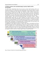
Nowadays, by reconsidering the energy and production system from an improvement of
energy conversion efficiency and energy saving point of view, the concept of co-production
of energy and products has been developed. However, to realize co-production, it is
Biofuel's Engineering Process Technology
318
necessary to analyze and optimize the heat and power required for production in each
process. Therefore, the authors have developed self-heat recuperation technology based on
exergy recuperation (Kansha et al. 2009) and applied it to several chemical processes for co-
production (Fushimi et al. 2011, Kansha et al. 2010a, 2010b, 2010c, 2011, Matsuda et al.2010).
In this chapter, self-heat recuperation technology is introduced and applied to the
separation processes in bioethanol production for co-production. Moreover, the feasibility
and energy balance for co-production of bioethanol and power using biomass gasification
based on self-heat recuperation is discussed.
2. Energy balance for conventional bioethanol production
It assumed that the amount of energy in feed stock wet biomass is 100 and that 50% of this
energy consists of that from reactant sugars, such as starch, cellulose and others. Thus, the
amount of energy of the original component of sugar (50) transfers to ethanol (46) and heat
(4) through chemical reactions (saccharification and fermentation) with water. This energy is
estimated from the following calculation; the caloric value of sugar is 685 kcal/mol, the
caloric value of ethanol is 316 kcal/mol and 2 mol ethanol is produced from 1 mol sugar
through the above reaction. The pure ethanol product is then separated by distillation and
additional heat energy (23) is required for this distillation work when azeotropic distillation
is used for the separation. Non-reactants contain a large amount of water, for which the
higher heat value is almost equal to the evaporation heat, leading to a net heat value of 0.
The above energy relation is shown in Fig. 1. Beyond this, some additional energy is
required to produce heat energy from the wet biomass for distillation (23). This additional
energy (15) is used to dry the wet biomass in a heater to produce dry biomass that is used as
fuel for distillation. Figure 2 shows the total energy balance including this additional energy.
It is noted that 50-80% moisture content in wet biomass is assumed in this energy analysis,
because many types of wet biomass exist in this range, such as those that originate from
ligneous, garbage and sludge. It can be seen from Fig. 2 that 138 units of energy in the wet
biomass feed stock is required to produce 46 energy units of ethanol and that about 1/3 of
the energy of the wet biomass can be utilized as bioethanol for fuel. Thus, 2/3 of the wet
biomass feed stock energy is wasted. Even though this wasted heat energy could potentially
be heat sources for other processes, the exergy ratio and temperature of the waste heats are
quite low. Thus, it is difficult to achieve energy saving from this by heat integration
technologies such as cascading utilization. In fact, the highest required temperature during
bioethanol production is normally at the distillation column reboiler and this temperature is
lower than 150
°
C. This heat is exhausted from the condenser at below 100
°
C. To utilize the
biomass energy more effectively, it is clear that the energy consumption during distillation
for separating water and product ethanol and for drying of the wet biomass must be
reduced. When an integrated system of distillation and membrane separation processes are
utilized to substitute for azeotropic distillation, the energy required can be decreased from
23 to 12 units (8: distillation, 4: membrane separation). However, the pressure difference for
membrane separation requires electric power. If we assume that the power generation
efficiency from dry biomass is 25% and 75% of the energy for the membrane separation
process is provided by electricity, 35 energy units from wet biomass are required for
distillation and dehydration by membrane separation.
Co-production of Bioethanol and Power
319
100
46
distillation
4
heat
ethanol
wet residue
50
wet biomass
heat
23
chemical
reaction
Fig. 1. Energy balance for bioethanol production
100
46
distillation
4
heat
ethanol
wet residue
50
wet biomass
heat
23
chemical
reaction
38
wet biomass
waste heat
waste heat
23
15
Fig. 2. Total energy balance for bioethanol production
3. Self-heat recuperation technology and self-heat recuperative processes
Self-heat recuperation technology (Kansha et al. 2009) facilitates recirculation of not only
latent heat but also sensible heat in a process, and helps to reduce the energy consumption
of the process by using compressors and self-heat exchangers based on exergy recuperation.
In this technology, i) a process unit is divided on the basis of functions to balance the
heating and cooling loads by performing enthalpy and exergy analysis, ii) the cooling load is
recuperated by compressors and exchanged with the heating load. As a result, the heat of
Biofuel's Engineering Process Technology
320
the process stream is perfectly circulated without heat addition, and thus, the energy
consumption for the process can be greatly reduced. By applying this technology to each
process (distillation and dehydration), the energy balance for the ethanol production can be
changed significantly from that described above. In this section, the design methodology for
self-heat recuperative processes is introduced by using a basic thermal process, and the self-
heat recuperative processes applied to the separation processes are then introduced.
3.1 Self-heat recuperative thermal process
To reduce the energy consumption in a process through heat recovery, heating and cooling
functions are generally integrated for heat exchange between feed and effluent to introduce
heat circulation. A system in which such integration is adopted is called a self-heat exchange
system. To maximize the self-heat exchange load, a heat circulation module for the heating
and cooling functions of the process unit has been proposed, as shown in Figure 3 (Kansha
et al. 2009).
Figure 3 (a) shows a thermal process for gas streams with heat circulation using self-heat
recuperation technology. In this process, the feed stream is heated with a heat exchanger
(1→2) from a standard temperature, T
0
, to a set temperature, T
1
. The effluent stream from
the following process is pressurized with a compressor to recuperate the heat of the effluent
stream (3→4) and the temperature of the stream exiting the compressor is raised to T
1
’
through adiabatic compression. Stream 4 is cooled with a heat exchanger for self-heat
exchange (4→5). The effluent stream is then decompressed with an expander to recover part
of the work of the compressor. This leads to perfect internal heat circulation through self-
heat recuperation. The effluent stream is finally cooled to T
0
with a cooler (6→7). Note that
the total heating duty is equal to the internal self-heat exchange load, Q
HX
, without any
external heating load, as shown in Fig. 3 (b).
In the case of ideal adiabatic compression and expansion, the input work provided to the
compressor performs a heat pumping role in which the effluent temperature can achieve
perfect internal heat circulation without any exergy dissipation. Therefore, self-heat
recuperation can dramatically reduce energy consumption.
Figure 3 (c) shows a thermal process for vapor/liquid streams with heat circulation using
the self-heat recuperation technology. In this process, the feed stream is heated with a heat
exchanger (1→2) from a standard temperature, T
0
, to a set temperature, T
1
. The effluent
stream from the subsequent process is pressurized with a compressor (3→4). The latent heat
can then be exchanged between feed and effluent streams because the boiling temperature
of the effluent stream is raised to T
b
’ by compression. Thus, the effluent stream is cooled
through the heat exchanger for self-heat exchange (4→5) while recuperating its heat. The
effluent stream is then depressurized by a valve (5→6) and finally cooled to T
0
with a cooler
(6→7). This leads to perfect internal heat circulation by self-heat recuperation, similar to the
above gas stream case. Note that the total heating duty is equal to the internal self-heat
exchange load, Q
HX
, without any external heating load, as shown in Fig. 3 (d). It can be
understood that the vapor and liquid sensible heat of the feed stream can be exchanged with
the sensible heat of the corresponding effluent stream and the vaporization heat of the feed
stream is exchanged with the condensation heat of the effluent stream. As a result, the
energy required by the heat circulation module is reduced to 1/22–1/2 of the original by the
self-heat exchange system in gas streams and/or vapor/liquid streams.
Co-production of Bioethanol and Power
321
Fig. 3. Self-heat recuperative thermal process a) process flow of gas streams, b) temperature-
heat diagram of gas streams, c) process flow of vapor/liquid streams, d) temperature-heat
diagram of vapor/liquid streams
3.2 Self-heat recuperative distillation
Expanding the self-heat recuperative thermal process to distillation processes in particular
(Kansha et al. 2010a, 2010b), a system including not only the distillation column but also the
preheating section, is developed in order to minimize the required energy, as shown in Fig.
4. A distillation process can be divided into two sections, namely the preheating and
distillation sections, on the basis of functions that balance the heating and cooling load by
performing enthalpy and exergy analysis, and the self-heat recuperation technology is
applied in these two sections. In the preheating section, one of the streams from the
distillation section is a vapor stream and the stream to the distillation section has a vapor–
liquid phase that balance the enthalpy of the feed streams and that of the effluent streams in
the section. In balancing the enthalpy of the feed and effluent streams in the preheating
section, the enthalpy of the streams in the distillation section is automatically balanced.
Thus, the reboiler duty is equal to the condenser duty of the distillation column. Therefore,
the vapor and liquid sensible heat of the feed streams can be exchanged with the sensible
heat of the corresponding effluent streams and the vaporization heat can be exchanged with
the condensation heat in each section.
Biofuel's Engineering Process Technology
322
Fig. 4. Self-heat recuperative distillation process a) process flow diagram, b) temperature-
heat diagram
Figure 4 (a) shows the structure of a self-heat recuperative distillation process consisting of
two standardized modules, namely, the heat circulation module and the distillation module.
Note that in each module, the summation of the enthalpy of the feed streams and that of the
effluent streams are equal. The feed stream in this integrated process module is represented
as stream 1. This stream is heated to its boiling point by the two streams independently
Co-production of Bioethanol and Power
323
recuperating heat of the distillate (12) and bottoms (13) by the heat exchanger (1→2). A
distillation column separates the distillate (3) and bottoms (9) from stream 2. The distillate
(3) is divided into two streams (4, 12). Stream 4 is compressed adiabatically by a compressor
and cooled down by the heat exchanger (2). The pressure and temperature of stream 6 are
adjusted by a valve and a cooler (6→7→8), and stream 8 is then fed into the distillation
column as a reflux stream. Simultaneously, the bottoms (9) is divided into two streams (10,
13). Stream 10 is heated by the heat exchanger and fed to the distillation column (10→11).
Streams 12 and 13 are the effluent streams from the distillation module and return to the
heat circulation module. In addition, the cooling duty of the cooler in the distillation module
is equal to the compression work of the compressor in the distillation module because of the
enthalpy balance in the distillation module.
The effluent stream (12) from the distillation module is compressed adiabatically by a
compressor (12→14). Streams 13 and 14 are successively cooled by a heat exchanger. The
pressure of stream 17 is adjusted to standard pressure by a valve (17→18), and the effluents
are finally cooled to standard temperature by coolers (15→16, 18→19). The sum of the
cooling duties of the coolers is equal to the compression work of the compressor in the heat
circulation module. Streams 16 and 19 are the products.
Figure 4 (b) shows the temperature and heat diagram for the self-heat recuperative
distillation process. In this figure, each number corresponds to the stream numbers in Figure
4 (a), and T
s
and T
b
are the standard temperature and the boiling temperature of the feed
stream, respectively. Both the sensible heat and the latent heat of the feed stream are
subsequently exchanged with the sensible and latent heat of effluents in heat exchanger 1.
The vaporization heat of the bottoms from the distillation column is exchanged with the
condensation heat of the distillate from the distillation column in the distillation module.
The heat of streams 4 and 12 are recuperated by the compressors and exchanged with the
heat in the module. It can be seen that all the self-heat is exchanged. As a result, the exergy
loss of the heat exchangers can be minimized and the energy required by the distillation
process is reduced to 1/6–1/8 of that required by the conventional heat exchanged
distillation process.
3.1.2 Self-heat recuperative azeotropic distillation for dehydration
Conventional azeotropic distillation processes, which have one distillation column for
dehydration to separate ethanol and another to separate water from their mixture, are
divided into three modules. The sum of the feed enthalpy is made equal to that of the
effluent stream enthalpy in each module to analyze the heating and cooling loads of all
process streams by following self-heat recuperation technology. According to this analysis,
the recovery streams are selected and the internal heat of the process stream in each module
can be recovered and recirculated using a compressor and heat exchanger through self-heat
recuperation technology.
Figure 5 a) shows the structure of the self-heat recuperative azeotropic distillation module
(Kansha et al. 2010c), consisting of three modules, namely, the first distillation module, the
heat circulation module, and the second distillation module. In this self-heat recuperative
distillation module, stream 1 represents a feed stream of the ethanol-water azeotropic
mixture and stream 2 represents an entrainer (benzene and cyclohexane) feed stream. These
streams are fed into the distillation column of the first distillation module. The vapor stream
from the first distillation process is compressed adiabatically by a compressor (4→5).
Subsequently, stream 5 is cooled in a heat exchanger (5→6), and the pressure and
Biofuel's Engineering Process Technology
324
Fig. 5. Self-heat recuperative azeotropic distillation process for dehydration a) process flow
diagram, b) temperature-heat diagram
temperature of stream 6 are adjusted by a valve and a cooler (6→7→8). The liquid stream (8)
is divided into two streams (9 and 10) in a decanter. Stream 9 consists mainly of the
entrainer, which is recycled to the feed benzene (3). The bottom (11) of the distillation
Co-production of Bioethanol and Power
325
column is divided into two streams (12 and 14). Stream 14 becomes a product stream (pure
ethanol). Stream 12 is heated in the heat exchanger and fed into the distillation column. In
the heat circulation module, the effluent stream (10) from the first distillation module is
heated in a heat exchanger and fed to the distillation column in the second distillation
module. At the same time, the recycled stream, which is the distillate stream from the
second distillation module, is adiabatically compressed by a compressor (18→27) and cooled
by exchanging heat in the heat exchanger (27→28). The pressure and temperature of stream
28 are adjusted by a valve and cooler (28→29→30) and stream 30 is fed into the distillation
column of the first distillation module as the recycled stream. Next, in the second distillation
module, the feed stream (15) is separated into the distillate (16) and the bottoms (17) by the
distillation column. The vapor distillate (16) is divided into two streams (18 and 19) by a
separator. Stream 18 is recycled to the heat circulation module, while stream 19 is
adiabatically compressed (19→20) and exchanged with the heat in a heat exchanger
(20→21). The temperature and pressure of stream 21 are adjusted by a valve and a cooler
(21→22→23), and then the effluent stream is fed into the distillation column. Subsequently,
the bottom stream (17) from the distillation column is divided into two streams (24 and 25).
Stream 25 is the product water. The other stream (24) is vaporized in the heat exchanger and
fed into the distillation column (26).
Figure 5 b) shows a temperature–heat diagram for the self-heat recuperative distillation
module for azeotropic distillation. Note that numbers beside the composite curve
correspond to the stream numbers in Figure 5 a). It can be seen that the latent heats of the
effluent streams are exchanged with those of the feed streams, as well as the sensible heats
in each module, leading to minimization of the exergy loss in the heat exchangers. From this
figure, it can be understood that all of process heat is recirculated without any heat addition
and the total heating duty was covered by internal heat recovery. All of the compression
work in each module was discarded into coolers in each module, because the sum of
enthalpy in the feed streams was equal to that of the effluent streams in each module when
using internal heat recovery. As this relationship indicates, the compression work was used
for inducing heat recovery and circulation in each module and exhausted as low exergy
heat. As a consequence, the energy required of the self-heat recuperative distillation module
for azeotropic distillation is 1/8 of that of the conventional azeotropic distillation process.
3.1.3 Self-heat recuperative drying
Biomass resources usually contain a large amount of moisture, leading to higher
transportation costs, debasement during storage, and reduction of thermal efficiency during
conversion. Drying is a key technology for utilizing the biomass (McCormick & Mujumdar
2008). In addition to the use of biomass for fuel, the energy required for drying occupies a
large amount of energy in the production due to the large latent heat of water during
evaporation. Moreover, this characteristic of the drying process is the same as for the
thermal and distillation processes. Therefore, a drying process based on self-heat
recuperation technology was recently proposed (Fushimi et al., 2011).
Figure 6 a) shows a schematic image of a self-heat recuperative drying process. The wet
sample is heated in a heat exchanger (1→2). The heated wet sample and vapor are then fed
into an evaporator (dryer) with dry gas to assist evaporation (16). The heat for evaporation
is supplied by superheated steam and gas (7). The hot dry sample (3) is separated and
cooled by the dry gas (15) (3
→5). After eliminating the unseparated sample to prevent it
from entering the compressor, the evaporated steam and gas (4) are compressed (7) by a
Biofuel's Engineering Process Technology
326
Fig. 6. Self-heat recuperative drying process for dehydration a) process flow diagram, b)
temperature-heat diagram
compressor. The sensible and latent heats of the compressed steam and gas are exchanged in
the heat exchanger (7→8) and fed into a condenser to separate the water and gas; the water
is then drained (10). The pressure and temperature of drain water are adjusted by a valve
Co-production of Bioethanol and Power
327
and cooler (10→12→14). Simultaneously, the pressure energy of the gas (9) is partially
recovered in an expander. The temperature of the gas is then cooled by a cooler (13). This
exhausted gas can be recycled as the gas feed (15). To use this gas as the dry gas feed,
makeup gas is necessary to compensate for the loss, because a small amount of gas dissolves
in water in the condenser. Considering a real application for a drying process, the dried
sample is separated immediately after the evaporation and reversed back to the heat
exchanger for heat utilization. However, with the aim of reducing drying time (higher
drying rate) and providing the driving force required in the drying process, gas that has
been preheated by the sample enters the evaporator. It should be noted that an increase in
gas flow rate causes an increase in the energy required for compression for the following
reasons: (1) an excess amount of gas must be compressed and (2) a smaller partial pressure
of steam requires larger compression pressure for condensation. Consequently, the gas flow
rate should be optimized.
Figure 6 b) shows a temperature-heat diagram of the self-heat recuperative drying process.
Note that the numbers beside the composite curve in this temperature-heat diagram
correspond to the stream numbers in Figure 6 a). It can be seen that the condensation heat of
the steam in the effluent stream (7→8) is exchanged with the evaporation heat of the feed
stream (1→2), as well as the sensible heats in a heat exchanger. At the same time, the heat of
solid sample after evaporation is exchanged with the heat of the gas stream in the other heat
exchanger and this heat is supplied to the feed solid sample. These lead to minimization of
the exergy loss in the heat exchangers. From this figure, it can be understood that all process
heat is recirculated without heat addition, and that the total heating duty is covered by
internal heat recovery. All of the compression work in each module was discarded into
coolers, because the base conditions of the stream are fixed at standard conditions. As a
consequence, to circulate the process stream heat in the process using heat exchangers and a
compressor, the energy required for the self-heat recuperative drying process is 1/7 of that
of the conventional heat recovered drying process.
4. Integration with biomass gasification
To adopt self-heat recuperative processes, it is necessary to generate power in substitution
for heat energy. According to the energy balance shown in Figs. 1 and 2, much residue with
insufficient heat value for utilization due to its high moisture content is produced during
bioethanol production. By integrating the self-heat recuperative drying process with power
generation, this wet biomass can be utilized for energy. In this section, an integrated system
for self-heat recuperative bioethanol production with biomass gasification is introduced.
4.1 Biomass gasification and its impact on the system
One of the easiest ways to generate power from biomass is direct combustion of biomass in
a boiler, wherein thermal energy is produced and power is generated from this thermal
energy by using a steam turbine (boiler and turbine generator). However, energy conversion
efficiency under this procedure is not good enough. To increase the conversion efficiency of
energy from biomass to power, biomass gasification reaction is used. Gasification reactions
can be divided into two mechanisms; pyrolysis and gasification by chemical reaction (partial
oxidation, etc.) Biomass gasification normally passes through both of these. After passing
through a series of gasification procedures, the gases are fed into a gas turbine, and then the
Biofuel's Engineering Process Technology
328
power is generated. Gasification reactions are normally endothermic reactions, and must be
provided with heat during reactions. However, the overall energy conversion efficiency will
be increased compared with the boiler and turbine generator. In addition, a further increase
in energy conversion efficiency, through a biomass-based integrated gasification combined
cycle (IGCC) technology has been investigated (Bridgwater 1995).
It is currently assumed that the energy conversion efficiency of biomass through power
generation and biomass gasification is 25%. The energy amount of the wet residue is 50 in
Figs. 1 and 2. It assumed that half of the energy amount of this wet residue can be utilized
for drying the biomass. According to the analysis of self-heat recuperative drying above, 1/8
of the amount of energy for water evaporation is required for power to dry this wet residue
using self-heat recuperative drying. This means that power (8) can be generated and a part
of this power (3) is used for drying, leading to 4% of the initial wet biomass being converted
to power as net energy (5) from the wet residue as shown in Fig. 7.
wet residue
50
exhausted
steam
28
power3
power5
waste heat20
Fig. 7. Power generation from wet residue during bioethanol production
5. Energy balance for self-heat recuperative bioethanol production
The same assumption as for section 2 is assumed; the amount of energy in the wet biomass
feed stock is 100, 50% of the energy value of the wet biomass consists of the energy value of
reactant sugars such as starch, cellulose and others, and the amount of energy of the original
sugar component (50) transfers to ethanol (46) and heat (4) through chemical reactions
(saccharification and fermentation) with water.
By applying the self-heat recuperative distillation and azeotropic distillation process to the
distillation and dehydration process, the additional heat energy for distillation is converted
to power. At the same time, the energy (23) in Figure 1 is reduced to 4. This value was
estimated from the energy reduction results from the self-heat recuperative processes in
section 3.
By integrating the aforementioned biomass gasification in section 4 with the self-heat
recuperative processes introduced in section 3, bioethanol (46) and power (1) can be
produced as co-products from wet biomass (100) during bioethanol production, as shown in
Fig. 8. Wet residue (non-reactants contain a large amount of water, for which the higher heat
value is almost equal to the required evaporation heat, leading to net heat value of 0) in Figs.
Co-production of Bioethanol and Power
329
1 and 2 can be utilized as the energy supply. Thus, it can be understood that 46% of the
energy of the wet biomass is transferred to the bioethanol and 1% of the energy to power.
Furthermore, the additional wet biomass (38) required to provide the distillation heat (23) is no
longer necessary for this bioethanol production. Thus, power (4) can be generated from
the
additional wet biomass by using a self-heat recuperative drying process and biomass
gasification, as shown in Fig. 9. As a result, 33% (= 46/138×100) of the energy of the wet
biomass is transferred to bioethanol and 4% (= 5/138×100) is transferred to power for co-
production. It can be said that this bioethanol production procedure achieves not only
energy savings but also reduction of exergy dissipation for the whole process, leading to
achievement of optimal co-production. In addition, substituting the azeotropic distillation
process by dehydration uses a membrane separation. All of the self-heat recuperative
processes and biomass gasification are applied to produce this energy. The energy required
can be decreased to 4 as power, where the same assumptions as used for the results
described above are used in the calculation, such that power generation efficiency from dry
biomass is 25% and 75% of the energy required for the membrane separation process is
provided by electricity. This value of power is the same as the energy required by applying
self-heat recuperative processes to the distillation and dehydration processes. Although the
energy required by membrane separation process is smaller than that of azeotropic
distillation in the conventional processes, it becomes equal after applying the self-heat
recuperative processes.
100
46
4
heat
ethanol
wet biomass
chemical
reaction
wet residue
50
exhausted
steam
28
power
3
power
5
waste heat20
distillation
power1
waste heat5
Fig. 8. Energy balance for bioethanol production with self-heat recuperation
Biofuel's Engineering Process Technology
330
100
46
4
heat
ethanol
wet biomass
chemical
reaction
wet residue
50
exhausted
steam
28
power
3
power
5
waste heat20
distillation
power1
waste heat5
power
4
38
wet biomass
exhausted
steam
34
Fig. 9. Total energy balance for bioethanol production with self-heat recuperation
6. Conclusion
In this chapter, a newly developed self-heat recuperation technology is introduced and the
feasibility of co-production of bioethanol and power by integration of self-heat recuperative
processes and biomass gasification for power generation is examined based on energy
balances. From analysis of the energy balance for the conventional bioethanol production
processes, a large amount of energy is consumed for separation of water (distillation and
drying) so that the operational costs for bioethanol production are high, limiting the
potential contribution of bioethanol to society. However, by incorporating self-heat
recuperative processes for distillation, azeotropic distillation and drying, not only are the
energy requirements reduced dramatically due to heat circulation in the processes, but also
wasted residue can be utilized as a power source through biomass gasification. Thus, it is
shown that co-production of bioethanol and power is feasible, enabling the economic impact
of the bioethanol product. Finally, this system is expected to help the uptake of bioethanol
and decrease global CO
2
emissions.
7. References
Baker, R.W. (2008). Membrane Technology, Introduction, In: Kirk-Othmer Separation
Technology 2nd Ed. Vol. 2, A. Seidel, (Ed.), 446-502, John Wiley & Sons, ISBN 978-0-
470-12741-4, NJ, USA
Co-production of Bioethanol and Power
331
Bridgwater, A.V. (1995). The technical and economic feasibility of biomass gasfication for
generation, Fuel, Vol. 74, No. 5, pp. 631-653, ISSN 0016-2361
Cardona, C.A.; Sanchez, O.J. & Gutierrez, L.F. (2010). Process Synthesis for Fuel Ethanol
Production, ISBN 978-1-4398-1597-7, FL, USA
Doherty, M.F. & Knapp, J.P. (2008). Distillation, Azeotropic and Extractive, In: Kirk-Othmer
Separation Technology 2nd Ed. Vol. 1, A. Seidel, (Ed.), 918-984, John Wiley & Sons,
ISBN 978-0-470-12741-4, NJ, USA
Fair J.R. (2008). Distillation, In: Kirk-Othmer Separation Technology 2nd Ed. Vol. 1, A. Seidel,
(Ed.), 871-917, John Wiley & Sons, ISBN 978-0-470-12741-4, NJ, USA
Fushimi, C.; Kansha, Y.; Aziz, M.; Mochidzuki, K.; Kaneko, S.; Tsutsumi, A.; Matsumoto, K.;
Yokohama, K.; Kosaka, K.; Kawamoto, N.; Oura, K.; Yamaguchi, Y. & Kinoshita, M.
(2011). Novel drying process based on self-heat recuperation technology, Drying
Technology, Vol. 29, No. 1, pp.105-110, ISSN 0737-3937
Hallale, N. (2008). Process Integration technology, In: Kirk-Othmer Separation Technology 2nd
Ed. Vol. 2, A. Seidel, (Ed.), 837-871, John Wiley & Sons, ISBN 978-0-470-12741-4, NJ,
USA
Huang, H J.; Ramaswamy, S.; Tschirner, U.W. & Ramarao, B.V. (2008). A review of
separation technologies in current and future biorefineries, Separation and
Purification Technology, Vol. 62, No. 1, pp.1-21, ISSN: 1383-5866
Kansha, Y.; Tsuru, N.; Sato, K.; Fushimi, C. & Tsutsumi, A. (2009). Self-heat recuperation
technology for energy saving in chemical processes, Industrial and Engineering
Chemistry Research, Vol. 48, No. 16, pp.7682-7686, ISSN 0888-5885
Kansha, Y.; Tsuru, N.; Fushimi, C.; Shimogawara, K. & Tsutsumi, A. (2010a). An innovative
modularity of heat circulation for fractional distillation, Chemical Engineering
Science, Vol. 65, No.1, pp.330-334, ISSN 0009-2509
Kansha, Y.; Tsuru, N.; Fushimi, C. & Tsutsumi, A. (2010b). Integrated process module for
distillation processes based on self-heat recuperation technology, Journal of Chemical
Engineering of Japan, Vol. 43, No. 6, pp. 502-507, ISSN 0021-9592
Kansha, Y.; Tsuru, N.; Fushimi, C. & Tsutsumi, A. (2010c). New design methodology based
on self-heat recuperation for production by azeotropic distillation, Energy & Fuels,
Vol. 24, No. 11, pp. 6099-6102, ISSN 0887-0624
Kansha, Y.; Kishimoto, A.; Nakagawa, T. & Tsutsumi, A (2011). A novel cryogenic air
separation process based on self-heat recuperation, Separation and Purification
Technology, Vol. 77, No. 3, pp. 389-396, ISSN 1383-5866
Kemp, I.C. (2007). Pinch Analysis and Process Integration A User Guide on Process Integration for
the Efficient Use of Energy 2nd Ed., Elsevier, ISBN 13 978-0-75068-260-2, Oxford, UK
Matsuda, K.; Kawazuishi, K.; Hirochi, Y.; Sato, R.; Kansha, Y.; Fushimi, C.; Shikatani, Y.;
Kunikiyo, H. & Tsutsumi, A. (2010). Advanced energy saving in the reaction
section of the hydro-desulfurization process with self-heat recuperation
technology, Applied Thermal Engineering, Vol. 30, No. 16, pp. 2300-2305, ISSN
1359-4311
McCormick, P.Y. & Mujumdar, A.S. (2008). Drying, In: Kirk-Othmer Separation Technology 2nd
Ed. Vol. 1, A. Seidel, (Ed.), 984-1032, John Wiley & Sons, ISBN 978-0-470-12741-4, NJ,
USA
Modla, G. & Lang P. (2008). Feasibility of new pressure swing batch distillation methods,
Chemical Engineering Science, Vol. 63, No. 11, pp. 2856-2874, ISSN 0009-2509
Mousdale, D.M. (2010). Introduction to Biofules, CRC Press, ISBN 978-1-4398-1207-5, FL, USA
Wynn, N.P. (2008). Pervaporation, In: Kirk-Othmer Separation Technology 2nd Ed. Vol. 2,
A.
Seidel, (Ed.), 533-550, John Wiley & Sons, ISBN 978-0-470-12741-4, NJ, USA
Biofuel's Engineering Process Technology
332
Zamboni, A.; Shah, N. & Bezzo, F. (2009a). Spatially Explicit Static Model for the Strategic
Design of Future Bioethanol Production Systems. 1. Cost Minimization, Energy &
Fuels, Vol. 23, No. 10, pp. 5121-5133, ISSN 0887-0624
Zamboni, A.; Shah, N. & Bezzo, F. (2009b). Spatially Explicit Static Model for the Strategic
Design of Future Bioethanol Production Systems. 2. Multi-Objective Environmental
Optimization, Energy & Fuels, Vol. 23, No. 10, pp. 5134-5143, ISSN 0887-0624
15
Conversion of Non-Homogeneous
Biomass to Ultraclean Syngas and
Catalytic Conversion to Ethanol
Stéphane C. Marie-Rose, Alexis Lemieux Perinet and Jean-Michel Lavoie
Industrial Research Chair on Cellulosic Ethanol
Department of Chemical and Biotechnological Engineering
Université de Sherbrooke, Sherbrooke, Québec
Canada
1. Introduction
Reducing greenhouse gas emissions, rising energy prices and security of supply are reasons
that justify the development of biofuels. However, food prices recorded in 2007 and 2008
affected more than 100 million of people that became undernourished worldwide (Rastoin,
2008) The food crisis has been caused by several factors: underinvestment in agriculture,
heavy speculation on agricultural commodities and competition of biofuels vs. food. It is
estimated that by 2050, it will be essential to increase by 50% the food production to support
the 9 billion people living on the planet (Rastoin, 2008).
Recycling the carbon from residual waste to produce biofuels is one of the challenges of this
new century. Several companies have been developing technologies that are able to
transform residual streams into syngas, which is subsequently converted into alcohols.
"Green" ethanol plays an important role in reducing dependency toward petroleum and
providing environmental benefit, through its role in the fuel additive market. Ethanol is an
oxygenate and also serves as an octane enhancer. The waste-to-syngas approach is an
alternative to avoid the controversy food vs. fuel whilst reducing landfills and increasing
carbon recuperation. Using this approach, yields of ethanol produced are above 350
liters/dry tonne of feedstock entering the gasifier (Enerkem’s technology is taken as
example). Residual heat, also a product of the process, is used in the process itself and, as
well, it can be used for outside heating or cooling. Enerkem Inc. is moving the technology
from bench scale, to pilot, to demo to commercial implementation (a 12,500 kg/h of sorted
and biotreated urban waste, is being constructed in Edmonton, Alberta). Economics of the
process are favorable at the above commercial capacity, given the modular construction of
the plant, reasonable operational costs and a tipping fee for the residue going into the
gasifier.
The first part of this chapter will present feedstock preparation, gasification and gas
conditioning. The characteristics of the heterogeneous feedstock will determine its
performance during gasification for syngas production whose composition has the
appropriate H
2
/CO ratio for downstream synthesis. The second part of the chapter will be
directed at the methanol synthesis in a three-phase reactor using syngas. The third and last
part of the chapter will focus on the catalytic steps to convert methanol into bio-ethanol.
Biofuel's Engineering Process Technology
334
2. Synthesis gas (syngas) production by gasification
2.1 Characteristics and composition of heterogeneous wastes as feedstock
Biomass is defined as an organic material derived from plants or animals that contain
potential chemical energy; for example wood, which was the first fire source used by
mankind, and which is still used today by population for cooking and heating.
At world scale, biomass is now the fourth largest energy source, but it has the capacity to
become the first. Photosynthesis can store up to 5-8 times more energy in biomass annually
than the actual world energy consumption (Prins et al., 2005). The basic reaction of
photosynthesis is as follow: carbon dioxide and water are converted to glucose and oxygen,
an endothermic process for which the energy is supplied by photons. Examples of biomass
are residues from agriculture or from the forest industry such as branches, straw, stalks, saw
dust, etc. An important example of residual agricultural biomass is related to the ethanol
production from sugar cane in Brazil which produces 280 kg of residual bagasse at 50% of
dry solids. Lignocellulosic materials can be collected and recovered because this material
has some energetic content (Ballerini and Alazard-Toux, 2006), however, leaving a part of
this material on place is imperative since it keeps the soil fertile.
It is important for governments and citizens to realize that hydrocarbon-based waste
material is another source of energy that should be taken advantage on. Waste can be solid
or liquid form. It can be land filled, incinerated or converted. Municipal solid waste used
electrical transmission poles and railroad ties treated with creosote, sludge from wastewater
treatment and pulp and paper industries, wood from construction and demolition
operations which contains paints and resins, etc., are all materials that contain carbon that
can be valorized in bio-refineries such as the one Enerkem is constructing (2011) in
Edmonton, AB.
Assessment of residual biomass or Municipal Solid Waste (MSW) as feedstock to produce
bio-ethanol requires a basic understanding of feedstock composition and of the specific
properties that dictates its performance as feed in the gasifier. The most important are:
moisture content, ash content, volatile matter content, elemental composition and heating
value.
The moisture content of biomass is the quantity of water in the material, expressed as
percentage of material weight. This weight can be referred to on a wet basis or on a dry
basis. If the moisture content is determined on a “wet” basis, the water’s weight is expressed
as a percentage of the sum of the weight of the water, ash, and dry- ash free matter. It is
sometimes necessary to dry the feedstock to a certain level in order to maximize the
gasification reaction. Indeed, more moisture is transferred by a higher consumption of
oxygen in order to keep the ideal temperature in the gasifier. Temperature of gasification is
crucial on the process efficiency. An optimum exists with just the right amount of oxygen
needed to perform completely the gasification reaction. This represents a temperature of
about 660°C for biomass with 20 % of moisture and about 695°C for biomass with 10 % of
moisture (Prins et al., 2005). If more oxygen is added, formation of carbon dioxide will
increase and gasification efficiency will drop; the heating value of the synthesis gas will thus
decrease (van der Drift et al., 2001). However, not enough oxygen will promote reduction of
carbon leading to an increase of methane formation.
The inorganic component (ash content) can be expressed the same way as the moisture
content. In general, the ash content is expressed on a dry basis. Both total ash content and
chemical composition are both important in regards of the gasification process. The
Conversion of Non-Homogeneous Biomass
to Ultraclean Syngas and Catalytic Conversion to Ethanol
335
composition of the ash affects its behaviour under high temperatures of combustion and
gasification. For example, melted ash may cause problems in both combustion and
gasification reactors. These problems may vary from clogged ash-removal caused by
slagging ash to severe operating issue in fluidized bed systems. Measurement of ash melting
point is thus crucial.
Volatile matter refers to the part of biomass that is released when the biomass is heated
beyond its dehydration temperatures. During this heating process the biomass decomposes
into volatile gases and solid char. Biomass typically has a high volatile matter content (up to
80%), whereas coal has a low volatile matter content (<20%).
Elemental composition of the ash-free organic component of residual biomass is relatively
uniform. The major components are carbon oxygen and hydrogen. Most biomass also
contains a small proportion of nitrogen and sulfur. Table 1 presents the elementary
composition of biomass as derived from ultimate analyses.
Element Wt% (dry basis)
Carbon 44 - 51
Hydrogen 5.5 - 6.7
Oxygen 41 - 50
Nitrogen 0.12 - 0.6
Sulfur 0 - 0.2
Table 1. Elementary composition of residual biomass
The heating value of a fuel is an indication of the energy chemically bound in the fuel with
reference to a standardized environment. The standardization involves the temperature,
state of water, and the combustion products. The calorific value is presented as the higher
heating value and the lower heating value. The higher heating value represents the heat
release per unit of mass when the material (at 25°C) is completely oxidized to carbon
dioxide and water and then returned to 25°C. A calorimetric bomb is the standard
instrument used to measure this value. The lower heating value is not taking into account
the energy supplied by the condensation of water (latent heat of vaporization of water at
25°C which is 2440 kJ/kg). The water includes moisture from the feedstock and the product
from the reaction between oxygen and hydrogen comprised in the raw material (Borman
and Ragland, 1998). Basic and complementary information about biomass intended for
gasification can be obtained via the proximate and ultimate analyses.
Proximate analysis measures moisture content, volatile matter, fixed carbon, ash content
and calorific value.
Ultimate analysis provides information about elementary composition of the biomass in
weight percentage of carbon, hydrogen, oxygen, sulphur and nitrogen. The carbon to
hydrogen ratio in the feedstock has a direct impact on the syngas, more particularly on the
ratio of H
2
/CO (Higman and van der Burgt, 2008).
Table 2 (depicted below) presents a comparison of different feedstock properties. Moisture
content was provided after drying of feedstock and compositions are approximated (Ciferno
and Marono, 2002).