Deploying RFID Challenges Solutions and Open Issues Part 11 doc
Bạn đang xem bản rút gọn của tài liệu. Xem và tải ngay bản đầy đủ của tài liệu tại đây (4.9 MB, 30 trang )
Services, Use Cases and Future Challenges for Near Field
Communication: the StoLPaN Project
287
A future extension of the service can be the introduction of individual pricing. As smart tags
on the products identify specific individual products and not just product categories, it is
possible to price similar products differently on the base of various factors – like closeness of
expiration date, damage of packaging, date of reception, etc.
4.3.5 Barcode and contactless
The original StoLPaN shopping process was developed for smart shopping operations,
where all the products are tagged with smart RFID tags. However, as fully operational and
completely smart retail operations are still a few years away, the solution has been extended
to the traditional barcode based environment. In such an environment, the smart shopping
cart does not have antennas, instead the PSA receives a built-in barcode reader. When a
product is selected, the customer waves it in front of the reader and when the reading is
successful a beep sounds. The process is similar with the loyalty sign-in and coupon
redemption features. All the previously described services are available as well. At the back
office level, the procedures are identical, no changes are necessary. Actually only the
antennas on the cart and the smart security gate need to be added to the StoLPaN smart
retail operation upon conclusion of a migration from the barcode based to RFID
identification. All other features of the new StoLPaN shopping process can be continued
without any modification and loss of investments.
5. Beyond the StoLPaN Project: future challenges for NFC-based services
The StoLPaN project ended in 2009, identifying four key topics for the future of NFC
ecosystem (StoLPaN consortium, 2009b). The consortium is still working with Global
Platform and NFC Forum to have the Project results endorsed by these standardization
bodies.
Beyond the StoLPaN project, the authors have identified three major points that have to be
considered for the mass adoption of NFC based applications and services. They are related
to the evolution of devices and UICCs, the improvement of OTA communication
capabilities, which make use of communication protocols such as Bearer Independent
Protocol (BIP) with the overlaying Card Application Toolkit_Transport Protocol (CAT_TP),
and finally the use of Smart Card Web Server (SCWS) technology for increasing SIM-based
applications’ capabilities.
The evolution of mobile devices includes the evolution of the UICC and related SIM logical
module too. The capacities of the SIM, as well as the applications supported, improve and
increase with the (U)SIM (Universal Subscriber Identity Module), which is used in 3G
mobile phones. By increasing its capacity, the (U)SIM can host the Secure Element with the
user’s personal information along with the keys for data protection. In the (U)SIM the SE has
a dedicated area for memory and logical elaboration. As we have already discussed in the
paper, according to the Smart Card Alliance and Global Platform (Global Platform, 2006),
the SE can be divided in different Security Domains (SD), which are separated and logically
distinct domains controlled by different Service Providers.
As each SD can be dynamically managed via wireless networks, users can choose their
favored services and personalize the carnet of applications on their mobile phone whenever
they wish. This improves the service usability, while the user’s satisfaction increases.
Moreover, the mobile phone becomes a real multitasking object used to pay, to travel, to get
discount coupons of the own preferred brands and to communicate with friends.
Deploying RFID – Challenges, Solutions, and Open Issues
288
As we already mentioned, compared with smart card technology, NFC applications stored
in the SE situated on the (U)SIM can be modified also after the issuance of the support
thanks to OTA update and management service. In order to increase the amount of
information exchangeable via wireless communication, OTA services can rely on new
protocols besides SMS: the Bearer Independent Protocol and the overtopping layer named
Card Application Toolkit_Transport Protocol. As a consequence of this improvement, it is
possible not only to transmit a greater amount of data, but also to establish a more secure
and reliable communication. More in detail, the BIP and the CAT_TP are able to open a
channel for the transmission of data between the device, the OTA Server and the (U)SIM
card. The communication channel can be opened either by the client or by the OTA Server,
i.e. by the (U)SIM by means of a command to the host device or by the OTA Server by
means of a SMS sent to the (U)SIM.
Finally, the future for mobile applications, even the NFC-based ones, is to use a web-
compliant logic also for the user interface. The (U)SIM already offers a suitable space to host
the Smart Card Web Server (SCWS), which is practically a web server stored locally on the
UICC (Madlmayr et al., 2008). Through this Web Server the user can rapidly access to
multimedia contents both static and dynamic. By using NFC in combination with a SCWS
(now directly connected on the USIM) user can enjoy a richer, more consistent and more
intuitive experience without paying any Internet connection fee, as he can benefit from local
contents similar to the Internet ones. Moreover, since the MNO can update and manage the
contents remotely, it can increase its offer to the end-user.
6. Conclusions
In this paper the authors presented the services, use cases and the future challenges for Near
Field Communication, which is the most customer-oriented one among RFID technologies,
as it can be described as the integration of an HF reader into the most popular personal
device worldwide, i.e. the mobile phone.
After detailing NFC communication modes (card emulation, peer-to-peer and reader/writer
modes) and related use cases such as payment, ticketing and information retrieval, the
authors focused the attention on the standardization and interoperability within the NFC
ecosystem that NFC based services need to achieve in order to reach mass adoption.
The authors presented the results of the research activities carried out by the StoLPaN
consortium during a three-year Project co-funded by the European Commission.
The StoLPaN consortium has worked on overcoming interoperability issues, mainly dealing
with application-level standardization, which has not been considered by standardization
bodies yet. The consortium elaborated a procedure for dynamic card content management
of Secure Elements placed in a mobile handset, identifying key and supporting roles within
the NFC ecosystem. Moreover, the consortium has detailed the technical environment
necessary for the dynamic management of NFC services, building a proof-of-concept
prototype of the NFC wallet application based on a component structure. Finally, StoLPaN
has demonstrated the effectiveness and the efficiency of the solution in a smart retail
environment, tracing the way forward for the migration from traditional, barcode based,
shopping to a smart shopping environment with the support of applications and services
that use RFID and NFC technologies.
Beyond the results carried out during the three-year StoLPaN project, the authors have
finally identified other three major points that have to be considered for the mass adoption
Services, Use Cases and Future Challenges for Near Field
Communication: the StoLPaN Project
289
of NFC-based services and applications. These are related to the evolution of the (U)SIM, the
improvement of OTA protocols such as BIP and CAT_TP and to the migration to a web-
compliant logic for the user interface making use of new technologies such as Smart Card
Web Server.
7. Acknowledgment
The authors would like to thank their partners in the Framework of the IST-FP6 project
StoLPaN (Store Logistic and Payment with NFC).
8. References
Benyó, B., Vilmos, A., Kovacs, K., Kutor, L., (2007) NFC Applications and Business Model of
the Ecosystem. Proc. of the 16th IST Mobile and Wireless Communications Summit.
Budapest, Hungary, 2007.07.01-2007.07.05., pp. 1469-1473. Paper 576.
Benyó, B., Vilmos, A., Fördős, G., Sódor, B., Kovács, L., (2009) The StoLPan View of the NFC
Ecosystem. Proc. of WTS 2009, 8th Wireless Telecommunications Symposium.
Prága, Csehország, 2009.04.22-2009.04.24., 5p., Paper 1569183809.
EPC 492-09, (2010), White Paper Mobile Payments, 1st Edition, Available from
/>ts_id=402
ETSI TS 102 190 V1.1.1: Near Field Communication (NFC) IP-1; Interface and Protocol
(NFCIP-1), (March 2003), Available from
ETSI TS 102 622 V.7.5.0 : Smart Cards; UICC - Contactless Front-end (CLF) Interface; Host
Controller Interface (HCI) (Release 7), (June 2009).
ETSI TS 102 613 V.7.7.0 : Smart Cards; UICC - Contactless Front-end (CLF) Interface; Part 1:
Physical and data link layer characteristics (Release 7), (October, 2009).
GlobalPlatform, (2006), Card Specification Version 2.2, Available from
.
GSMA, (2007a), Mobile NFC services, Version 1.0, Available from
GSMA, (2007b), Pay-Buy-Mobile Business Opportunity Analysis, Version 1.0, Available
from
GSMA (2007c), Mobile NFC technical guidelines, Version 2.0, Available from
Innovision Research & Technology plc, (2007), Turning the NFC promise into profitable,
everyday applications, In: Near Field Communication in the real world – part I,
Available from
ISO/IEC 14443 : Identification cards – Contactless integrated circuit(s) cards – Proximity
cards (Part 1-4), Available from .
ISO/IEC 18092 (ECMA-340): Information technology - Telecommunications and information
exchange between systems - Near Field Communication - Interface and Protocol
(NFCIP-1), (First Edition, 2004.04.01), Available from
ISO/IEC 21481 (ECMA 352): Information technology - Telecommunications and information
exchange between systems - Near Field Communication Interface and Protocol -2
(NFCIP-2), (January 2005), Available from
Deploying RFID – Challenges, Solutions, and Open Issues
290
Kannainen, L., (2009). Global overview of commercial implementations and pilots of NFC
payments during 2009, In : Smart Card Technology International - globalsmart.com,
08.11.2010, Available from
Madlmayr, G., Brandlberger, D., Langer, J., Scharinger, J., (2008), Evaluation of SmartCard
Webserver as an Application Platform from a User’s Perspective, Proceedings of
MoMM 2008.
Mayes, K., Markantonakis, K., (Eds.). (2008). Smart Cards, Tokens, Security and Applications,
Spinger, ISBN: 978-0-387-72197-2, New York.
Mobey Forum, (2010), Alternatives for Banks to Offer Secure Mobile Payments, Version 1.0.
NFC Forum, (2006), NFC Data Exchange Format (NDEF) Technical Specification, Version
1.0.
StoLPaN consortium, (2008a), Dynamic Management of multi-application Secure Elements,
Public Whitepaper, Available from
StoLPaN consortium, (2008b), Dynamic NFC wallet, Public Whitepaper, Available from
StoLPaN consortium, (2009a), StoLPaN Smart Shopping, Public Deliverable, Available from
StoLPaN consortium, (2009b), NFC Application Distribution – Proposed Business Models,
Public Deliverable, Available from
Wiechert, T., Thiesse, F., Schaller, A., & Fleisch, E., (2009a), NFC based Service Innovation in
Retail: An explorative Study. In Proceedings of the 17th European Conference on
Information Systems (ECIS)12, Verona, Italy, June 8-9 2009, p12.,
ECIS2009-0587.R1
Wiechert, T., Schaller, A., & Thiesse, F., (2009b), Near Field Communication Use in Retail
Stores: Effects on the Customer Shopping Process. In Mobile und Ubiquitäre
Informationssysteme - Entwicklung, Implementierung und Anwendung137-141.
Bonn, Germany: Gesellschaft für Informatik e.V. (GI). - ISBN 978-3-88579-240-6.
16
RFID Applications in Cyber-Physical System
Nan Wu
1
and Xiangdong Li
2
1
Nanjing University
2
The City University of New York
1
China
2
US
1. Introduction
A cyber-physical system (CPS) is a system which combines and coordinates the physical
system and informatics or computational entities (including computation and communication)
into a tight mode. Nowadays we can see the applications of cyber-physical system in the fields
of aerospace, automotive, chemical processes, civil infrastructure, energy, healthcare,
manufacturing, transportation, entertainment, and consumer appliances.
First, the typical feature of a cyber-physical system is the combination, the CPS is a system
deeply combined with computing and physical system. Compared with the so-called
embedded system, the percentage of the physical component involved in a CPS is higher
than those in an embedded system (shown in Figure 1). In an embedded system, the main
focus is on the computational elements, not on the link between the computational and
physical elements. Second, unlike a traditional embedded system, usually a CPS is designed
as a network of the interaction between the physical input and output, instead of being as a
standalone device. The notion is tied to the concepts of robotics and sensor networks. The
improvement of the link between computational and physical elements using the advances
in science and engineering will boost the use of the cyber-physical systems. Several
applications of the use of CPS are “the intervention (e.g., collision avoidance), precision (e.g.,
robotic surgery and nano-level manufacturing), operation in dangerous or inaccessible
environments (e.g., search and rescue, firefighting, and deep-sea exploration), coordination
(e.g., air traffic control, war fighting), efficiency (e.g., zero-net energy buildings), and
augmentation of human capabilities (e.g., healthcare monitoring and delivery)” [1].
A Radio-frequency Identification (RFID) system is a typical cyber-physical system because of
its mainly functional and physical components: (1) The computational element: although a
passive RFID tag normally only contains the storage function, but the whole RFID system
(mainly in a RFID tag reader) and the post-processing system have the computing and data-
processing functions; (2) The controlling element: usually a RFID system is under the control
of an inner micro- control-unit (MCU); (3) The communication element: in a RFID system,
nearly all the information is exchanged via the wave of radio frequency (RF), the data and
controlling flows are established via a 2-way RF communication. During the work process, the
traditional RFID uses the electronic tags which are placed on the items to track their locations
or descriptions. The RFID tags are tiny microchips that can, in some cases, be fabricated
smaller than a pinhead or a grain of sand. The chip is attached to a tiny antenna which allows it
to communicate and transmit information. Figure 2 is a blown up view of a simple RFID tag [2].
Deploying RFID – Challenges, Solutions, and Open Issues
292
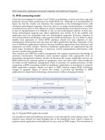
Fig. 1. Three main functional components in a cyber-physical system
Fig. 2. The structure and outside view of RFID tags
Mostly the regular RFID systems for the civil use are classified into three types – the passive,
the semi-passive, and the active RFID. A passive tag is dormant until it is triggered by a
signal from a RFID reader. A passive tag does not have a built-in power supply, so it needs
the radio frequency energy (electromagnetic wave) from the RFID reader. These tags are
particularly popular in use because they can draw the power wirelessly, such that the size
and price can be reduced much. Furthermore, these tags can be applied on almost
everything because of the wide use of the wireless power supply. A semi-passive tag
RFID Applications in Cyber-Physical System
293
contains a small battery to function an inner timer or random access memory. However, the
power supply does not actively communicate with a reader until it is requested. When it is
requested, it uses the radio wave power to transmit the information to the reader, which is
the same as that of a passive one. An active tag has a more powerful small power source (a
battery or other changeable DC source) built-in. Unlike the semi-passive tags, it can actively
communicate with the readers without the need of radio wave power.
The most common type of RFID tags used on the market is the passive type and the tags rely
on the readers for the energy. A RFID reader usually has a Radio Frequency (RF) module
that allows it to transmit and receive messages. It is also manufactured with additional
interfaces (e.g. RS 232 or RS485) to allow the connection with the PC’s, etc. Figure 3 shows a
simple diagram of the communication between a RFID reader and a tag (or transponder).
The “application” shown in the diagram is an enterprise network infrastructure.
Fig. 3. A Simple passive RFID system diagram
In this chapter, we will study the mixture of a cyber-physical system using the RFID
technology. As mentioned above, in a traditional embedded system with a built-in power
supplier, using the passive RFID tags is subject to losing the processing ability without the
RFID tag readers. To meet the requirements of CPS key application, it is necessary for the
RFID tags to contain the batteries and operate the inner MCU and microchips. In the
following sections, we will discuss the design on the key applications of the RFID system
with the active mode [3].
2. Active RFID system
As discussed in the previous section, usually a passive tag holds a unique identification
code or a number of 8 bytes in length, along with other small pieces of information. The
active and passive tags are different based on the types of information they store. A
common passive tag only stores the object identification information, whereas an active tag
stores the object description and its transportation history, in addition to the identification
information. A real active RFID tag is shown in Figures 4 and 5 [4, 8].
Deploying RFID – Challenges, Solutions, and Open Issues
294
Fig. 4. A compacted active RFID tag
Fig. 5. An active RFID tag with a changeable antenna
To meet the requirements of the key application of cyber-physical system, we should
analyze the applicability of a passive RFID system with details. Usually, the microchip in a
passive RFID tag is sealed with a plastic cover statically and cannot be altered from its
manufacture or configuration. But the information on the tags is able to be rewritten. There
are three different core devices which are able to re-write the data into the RFID tags [6]:
①EEPROMs (electrically erasable programmable read-only memory) are most commonly
used among these three. Usually an EEPROM memory capacity ranges from 16 bytes to 8
kilobytes. The disadvantage of using this device for the writing process is the high power
consumption. ②FRAMs (ferromagnetic random access memory)’s reading power
consumption is lower than that in the EEPROM. But the manufacturing problems in the past
cause an impact on its market acceptance. The FRAMs have a similar limit in the memory
capacity. ③SRAMs (static random access memory) are used especially in the microwave
systems and have very high writing cycles. In order to retain the data, it needs an
RFID Applications in Cyber-Physical System
295
uninterrupted power supply, such an auxiliary battery or some other power sources should
be equipped for the tags. This obviously limits its usefulness. The SRAMs memory capacity
ranges from 256 bytes to 64 kilobytes. From the manufactory experience, a RFID tag can be
read and written up to 10 billion times before its performance drops, so the future of this tag
is optimistic.
As mentioned in section 1, the application of CPS inclines to “more computation power”,
the RFID system using passive tags shows several disadvantages when examined with the
requirements of CPS applications.
• The processing ability of RFID tags is extremely based on the reader or the connected
computers. The tag has a very weak computing ability, so a passive RFID tag is barely
as an electrical ID container.
• A passive RFID tag is not able to take any kind of sensor to carry the environment data
because of the lack of the driving circuits.
• Even in an active region of a passive RFID reader, the energy supply from the radio
coupling of the electromagnetic coil is not sufficient for a more complex computation to
function the RFID card’s MCU.
• The two-way complex communication is subject to suffering more electromagnetic
interference (EMI) during the communications between the card and the reader, plus
the radio coupling interaction.
Due to these disadvantages, a passive RFID tag and its reader system cannot meet the
requirements of CPS applications. Table 1 is shown in Yamada’s research [5]:
Table 1. Classification of RFID tags
Apparently, an active RFID system can be described highly the likeness of wireless sensor,
which has shown to be a successful and mature system. The largest deployment of the active
RFID is done by US Department of Defense (DoD), the DoD uses the Savi active tags on each
of its over a million shipping containers that travel outside of US.
However, different from a pure wireless sensor system, an active RFID system network is a
kind of Ad-hoc network, that is, a heterogeneous network. From the communication
protocol point of view, an active RFID reader and its corresponding tags can work with a
one-to-many model (and vice versa): one tag can be coupled with many readers (the reader
can be defined as a base station in the Ad-hoc model). So when designing the active RFID
system protocols, we should consider the difference between the peer-to-peer model and
one-to-many model (or many-to-one).
From the network topological structure point of view, a heterogeneous network is wireless
based. It is a good carrier for the two-way wireless communication. Here, we define the
RFID system used in a CPS system as the followings:
RFID application in CPS = active RFID system + wireless sensor + protocols + network
collaborative mechanism
Deploying RFID – Challenges, Solutions, and Open Issues
296
In the next section we will study a typical RFID application in CPS system.
3. A typical RFID application in CPS: a case study
This case study is about the use of an active RFID system which includes a few readers (as
the base station) and many active tags (as the sensors) to build an active wireless positioning
network, which is a pre-research one of our project [7].
The positioning based services for the geographic information are important in the civil
applications, such as the travelling, geographic measurement, harbour operation, driving or
logistics; as well as in the military, such as an emergency support or emergency logistics.
Today, the global positioning system (GPS) is the most widely used and most well
developed positioning system. A GPS receiver uses a high-precision referenced time from a
low-orbit satellite to conduct the distance measurement, and it calculates the position by
using the geometry methods. The GPS system provides a high positioning accuracy, an
excellent timeliness and a strong anti-interference ability. The GPS has many advantages,
but with a fatal weakness, that is, its positioning ability and performance are affected
distinctly when the receiver is out of the region of the GPS satellite’s signal. For example, in
an application of the military emergency logistics, when the military vehicle is running in a
tunnel or the soldiers are in a thick forest or in a construction, the GPS can not provide the
robust positioning service. Especially in a situation such as the need for a rapid response,
the loss of GPS performance may cause the possession lost or more casualties. To avoid this
problem, the in-door positioning based service is needed for both the military and the civil
applications. We study a kind of GPS-independent active positioning system, based on an
active RFID system and the TOA (time of arrival) technology and related algorithms [7].
Based on the theory, the distributed node location service uses the referenced base stations
(i.e. an active RFID reader, they have the absolute or relative positions of RFID tags) in a
distributed network. The node location service is a highly potential core service in the
location-based service when applied in a distributed scenario. It shows a great potential,
especially when it is used for the positioning in the complicated or blocked indoor/outdoor
environment, emergent logistics management, and disaster-relief emergent positioning, etc.
Currently, based on the positioned objects, the distributed node location service's algorithms
and the systems can be categorized into a self-node positioning and a target-node
positioning. Here we only focus on the self-node positioning. In the positioning technology,
a node in the network is recognized as a beacon node or an unknown node based on
whether the node is assigned or not assigned with the location information (relative location
or absolute location via the GPS or other devices). As the unknown nodes gaining more
relative information during the process, therefore, in order to reduce the overall networking
loads and the communication cost, the number of the beacon nodes should be limited.
We consider the unknown nodes in the network as the sensors with some special functions
(e.g. a function of measuring the distance) and the beacon nodes as the base stations, such
that the network with a specific topological structure is a heterogeneous wireless sensor
network (WSN). Generally, a well-designed WSN mainly contains the following units:
• Transmission units (including the distance sensors and A/D modules);
• Processing units (including the MCU and embedded software system);
• Communication units (including the radio frequency modules).
We could see clearly that these requirements can be well met based on the active RFID
system. In this section we address some key issues on the range based positioning service
and study a novel model of the node-location service based on the aforementioned CPS
RFID Applications in Cyber-Physical System
297
model. The theoretical analysis shows that this model can provide a good and stable
positioning accuracy and a strong robustness for the scenes where the network topology
structure or the node's surrounding environment varies. In addition, it also benefits the re-
organizing of the network and the corresponding the active RFID tags’ surviving time.
When we combine the node-location service with the proposed model, a new positioning
service mode is formulated, that is the wireless sensor network positioning technology.
Compared with the traditional wireless positioning technology, it provides new features
below:
• Large scale;
• Low hardware resource requirement;
• Non-centralized Ad-hoc network;
• Low energy cost;
• Self-organizing;
• Dynamic topology;
• High positioning accuracy;
• Dynamic positioning supported;
• Communication and positioning;
The accuracy of the range-free positioning service and its convergence rate highly
depends on the estimated accuracy on the network's average jumping distance. When the
anisotropy or the topological structure of this RFID system’s organized WSN becomes
complicate, the performance of the algorithm will be significantly weaken. Therefore,
compared with the range-free positioning algorithm, the range-based positioning
algorithm has such advantages as a better accuracy and a shorter response time. However,
on the other hand, it also holds some disadvantages, such as a higher requirement for the
hardware and the more power cost. To balance the advantages and the prices, we choose
a TOA (Time-of-Arrival)-based distance measurement technology under the WSN as the
prototype model.
According to the discussion above, we realize that the in the pursuit of the highly realizable
accuracy of the positioning sacrifices the fast response rate and narrow bandwidth with less
power cost. An optimization should be reached. We propose a method to simulate and
calculate (or optimize) this point by using a statistical model. A lower bound of the
positioning accuracy based on the TOA and WSN methods is also discussed in this section.
The algorithm of the TOA costs less hardware resource in the applications, it is helpful to
enhance the reliability and robustness of the model. Using the TOA distance estimation, we
can apply the trilateration method for the positioning, which is shown in Figure 6.
Considering the mixture of cyber-system and physical system; the aforementioned theory
can be designed as algorithms and be coded in MCU of the active RFID tags.
Figure 7 shows the experimental results of the proposed method. The detailed experimental
platform is described below.
We physically implemented the specified positioning equipment using the proposed model.
The equipment includes an IEEE 802.15.4a chirp spread spectrum (CSS) system, its time-
domain and frequency-domain characteristics are shown in the Fig 8. The receiving
sensitivity of beacon nodes and unknown nodes is greater than -97dBm. They work in a
duplex mode, cooperating with a gain antenna and a related operating system, and the
experiment shows a good signal-to-noise ratio (SNR). The average loaded RF power is only
1mW, which could significantly ensure the surviving time of the unknown nodes.
Deploying RFID – Challenges, Solutions, and Open Issues
298
Fig. 6. The estimation of the position of an unknown node by using the trilateration method
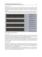
Fig. 7. The experimental results of the bacon-based active position system
The model system has a strong ability of the anti-multi-path-interference and anti-human-
interference. In the modulation, the pulse resolution is adjustable in order to be adapted in
different application environments. The networking protocol is uncomplicated and reliable;
it can be also added with a 128-bit hardware encryption, which can effectively prevent the
interference from outside and the disclosure of the location information.
Based on our prototype of the design, we have made the experimental product. Figure 9
shows the experiment platform which realizes the algorithm and the active RFID system.
We improved this product with a compact size and low-power consumption. The key
parameters of the tag are listed in Table 2.
Other product’s entities and the related software interface are listed in following Figures 10,
11 and 12.
RFID Applications in Cyber-Physical System
299
Fig. 8. The time-domain and frequency-domain characteristics of the CSS signal
Fig. 9. Experimental platform using RFID reader, tag and wireless transmitting system
Table 2. The compact-sized positioning active RFID tag
Deploying RFID – Challenges, Solutions, and Open Issues
300
Fig. 10. The indoor positioning sensor and active RFID positioning tag
Fig. 11. The related software running on the reader’s computer (in 2D mode, red spots
indicate the tags’ relative position and the blue shadow area is the error space in XY-plane)
RFID Applications in Cyber-Physical System
301
Fig. 12. The related software running on the reader’s computer (in 3D and live-action
modes. In the left, the yellow spot means the tags’ relative position, the purplish red shadow
area is the error space in XY-plane, and the blue cylinder is the height in Z-axial)
4. Summary
In conclusion, the active RFID system has shown the gain of a great potential for building a
highly-mixed system of information and the physical devices. In this chapter, we compare
the RFID system with a traditional wireless sensor network system and discuss the
applicability of the type of RFID systems. We propose and study the design idea,
methodology, product and experimental results of an active RFID based relative positioning
system.
Deploying RFID – Challenges, Solutions, and Open Issues
302
5. References
[1]
[2] Sztipanovits, J.; Stankovic, J. & Corman, D. Industry - Academy Collaboration in Cyber
Physical System (CPS) Research White Paper V.1 ,Georage Mason University, May 19,
2009
[3] Jalasto, M. Mobile phone applications for radio frequency identification systems, Proc. Reserach
Seminar on Telecommunications Bussiness II, Luukkainen S. Eds., April, 2005
[4]
[5] Yamada, I., Shiotsu, S., Itasaki, A., et al. Secure active RFID tag system, Ubicomp2005
Workshop
[6] Rhodes, J. RFID System Protocols and Standards Overview, Research Report CPET 384 -
Wide Area Networks, 2007
[7] Lai, X.; Li, J. ; Li, X ; & Wu, N. A novel model of node location service based on wireless sensor
networks and statistical method, Proc. SPIE Wireless Sensing, Localization, and
Processing, V, Sohail A. Dianat; Michael D. Zoltowski Eds., 2010
[8]
17
SAW Transponder –
RFID for Extreme Conditions
Alfred Binder, Gudrun Bruckner and René Fachberger
Carinthian Tech Research AG
Austria
1. Introduction
Harsh or hazardous environments, e.g. continuous furnaces, process chambers, rotating or
moving objects, require a robust wireless passive transponder technology for sensor and
RFID applications. The transponders’ operating temperature often exceeds 200°C in these
applications and is way above the thermal limit of CMOS devices. Surface acoustic wave
(SAW) devices are excellent candidates for high temperature applications as their operation
has been shown at temperatures of 1000°C (Hornsteiner, 1997). With the use of an RF (radio
frequency) antenna SAW devices can be interrogated passively and wirelessly.
The main advantage of surface acoustic wave sensors is their outstanding thermal stability
specially compared to semiconductors. The sensors utilize the piezo-effect that creates so-
called surface acoustic waves by means of a transducer structure on the surface of the
sensor. Metallization gratings, so called reflectors are used to supply the device with a
unique identification code (ID), achieved by pulse position coding (Reindl, 1998). This
allows using the device as a high temperature stable RFID transponder (radio frequency
identification). Depending on temperature or mechanical strain the surface acoustic waves
are also affected. These changes on the surface acoustic waves can be used to implement an
additional sensor functionality. In this way pressure sensors in combination with
temperature sensing have been demonstrated [Pohl,1997; Kalinin, 2004].
In ideal application fields of SAW based RFID systems environmental conditions like high
temperature or high doses of γ-radiation exist. Successful application examples are the
automatic identification of pressure sensors, vehicle identification in paint shops and several
tagging tasks in the steel industry. Often the temperature information contained in the
response signal gives valuable additional process information of the tagged goods.
This chapter gives an overview of SAW based RFID transponders made for extreme
conditions like temperatures up to 400°C or cryogenic temperatures down to –196°C. Their
function principle and system performance is explained and pertinent application examples
are given.
2. Principle of operation
A wireless surface acoustic wave based RFID system essentially comprises a reader unit
emitting and receiving radio waves and a SAW reflective delay line attached to an antenna,
building the transponder (Figure 1). For data acquisition, the impulse response of the SAW
Deploying RFID – Challenges, Solutions, and Open Issues
304
transponder is analysed by a digital signal processor. The response signal contains a pattern
of reflectors, which resembles for instance a binary, decimal or hexadecimal code. Utilizing
the natural sensitivity of the piezoelectric substrate crystal, e.g. on temperature or strain, the
SAW tag can operate as a sensor.
Fig. 1. SAW transponder interrogation setup.
The SAW RFID system is suited for high operating temperatures as it is purely based on
piezoelectricity and therefore fully passive. It makes use of the piezoelectric-substrate
lithium niobate. The operating principle of the system is as follows:
A high-frequency electromagnetic (EM) interrogation signal is picked up by the antenna of
the passive SAW device and conducted to a transducer. The interdigital transducer (IDT)
converts the received signal into a surface acoustic wave (SAW) by the converse
piezoelectric effect. The SAW propagates towards reflectors distributed in a characteristic
barcode-like pattern and is partially reflected at each reflector. The acoustic wave packets
returning to the IDT are reconverted into electrical signals by the IDT and sent back to the
request unit by the antenna. This response contains information about the number and
location of reflectors as well as the propagation and reflection properties of the SAW. It is
evaluated by the interrogation unit to extract the desired information.
In a particular design example eight reflectors are used to supply the SAW device with the
unique identification code (ID) and a temperature sensing functionality. The first response
pulse should have an adequate time delay towards the interrogation pulse to avoid
environmental electromagnetic reflections and echoes corrupting an early sensor response.
A practicable value for this delay time is 1.0 µs. In Figure 2, a typical impulse response of the
designed SAW tag is shown. The SAW’s edge reflection (at 0.4 µs) and crosstalk signal rests
can be seen in the time between 0 and 1 µs. Then, the tag’s eight response pulses rise clearly
out of the surrounding noise level (about 1 µs up to 2.25 µs). The first and last pulse take the
function of start- and stop-bit and are used for compensation of temperature changes, the
second pulse is additionally taken for temperature measurement. Via pulse position coding,
(Reindl, 1998) the other pulses are used to encode a unique ID comparable to an ID stored in
a microprocessor’s ROM.
SAW Transponder – RFID for Extreme Conditions
305
While wireless interrogation can be achieved at any readout frequency, there is only a
distinct number of radio frequency (RF) bands which are free for industrial-scientific-
medical (ISM) applications. Here, the ISM band from 2.4 GHz to 2.4835 GHz proved to be
most suitable as it has an adequate bandwidth (83.5 MHz) and an almost worldwide
geographical licence. At the same time it allows a read out at a distance of several meters. At
this frequency, the RF wavelength is about 13.5 cm, thus permitting the usage of simple and
small antennas, e.g. dipoles, slot- or patch antennas, favorably for the transponder part.
Fig. 2. Impulse response of a SAW transponder with eight reflectors.
2.1 Reader systems for SAW transponder
Reader systems for SAW transponders usually utilize the continuous wave radar principles.
Impulse radars could be considered but are inferior in cost and are not efficient in terms of
feeding the electromagnetic energy in the transponder. A set of three radar types are
investigated: First, a frequency modulated continuous wave (FMCW), second, a frequency
stepped (FSCW) and third, a switched frequency stepped (S-FSCW) radar. All three realized
types generate a RF ramp within the ISM band at 2.4 GHz. The FMCW radar is equipped
with a fast direct digital synthesis (DDS) based frequency synthesizer that provides fast
frequency sweeps of 100 µs duration (Figure 3). The DDS works with a frequency pre-
distortion to combat non-linear frequency chirps as reported in (Scheiblhofer, 2006). The Tx
and Rx paths have separate antennas to achieve better signal isolation. The front-end collects
during one frequency sweep 1024 data points. Data averaging is performed by repeated
frequency sweeps over the whole bandwidth.
The FSCW radar generates the frequency ramp with a phase locked loop (PLL) based
synthesizer (Figure 4). The synthesizer is significantly slower than the DDS providing sweep
Deploying RFID – Challenges, Solutions, and Open Issues
306
durations of 100 ms. During one frequency sweep the radar collects 636 data points.
Contrary to the FMCW the measurements are taken on discrete frequency steps.
The S-FSCW radar front-end is additionally equipped with Tx- and TRx switches (Figure 5).
The switches are accurately synchronized to the signal response of the SAW delay line
(Figure 2). The method yields in a significant reduction of environmental echoes and noise
(Stelzer, 2004). The radar collects 636 data points during one sweep. The FSCW and the
S-FSCW radar can average data either on a single frequency step or alike the FMCW over
the whole sweep.
Fig. 3. Block diagram of a FMCW radar front end.
Fig. 4. Block diagram of a FSCW radar front end.
SAW Transponder – RFID for Extreme Conditions
307
Fig. 5. Block diagram of an S-FSCW radar front end.
2.2 Package for SAW transponder
An important aspect for the transponder is the development of an appropriate packaging,
which is functional at high temperatures (HT). A metallic housing with glass feed-throughs,
withstanding temperatures up to 400°C is shown in Figure 6. The sensor tags’ fixation inside
the housing is done by a polyimide glue and its electrical interconnection by wire bonds. It
is essential that the packaging is hermetically sealed. This is best done by resistance welding
the lid to the socket. The weld is robust against high temperature and high temperature
gradients. A complete transponder tag, using a monopole antenna welded to the pins is the
simplest form of tag-antenna integration. This monopole tag is fully functional and does not
need any additional hardware or any power supply. It can be injection molded into various
plastics or ceramics depending on target applications. For optimized read range the
connector pins can be welded to a stainless steel slot antenna. The interconnection between
tag housing and antenna is done by laser welding, making this RFID transponder system
HT resistant well beyond 400°C. It can easily be screwed on metallic objects via the inte-
grated assembly units. By the design of this transponder, a metallic surface acts as a
Fig. 6. Transponder housing TO39 (left) and custom KOVAR
®
housing (right).
SAW
element
connector
pins
metal
housing
Deploying RFID – Challenges, Solutions, and Open Issues
308
reflector, increasing the antenna gain. This in turn doubles the operable readout range. An
alternative package is shown in Figure 6 (right). This KOVAR
®
package is optimized for
thermal conductivity to the sensing SAW element, thus increasing the temperature
dynamics by a factor 5.
3. System performance
The robustness of SAW transponder technology was proven with various temperature tests.
SAW transponders are not only stable at high temperatures; they even can be read out
operationally. In case the transponder is read out at high temperature a reduced read-out
distance has to be taken into account in the system design.
3.1 Durability
The durability of the packaged SAW devices has been tested by thermal aging (Fachberger,
2008). Several tags of each type of metallization were stored in an oven at temperatures of
300°C and 350°C. Measurements were made in an air-conditioned cabinet at 22°C. The
devices were placed in a test jig equipped with lateral interfering spring pins and measured
with a network analyzer (NWA). In some cases the contact pins were oxidized on the
surface; these pins had to be cleaned with a blade to achieve a good electrical contact to the
spring pins. For each measured device the weakest peak amplitude was recorded. The
rejection criterion was defined to be a decrease of more than 3 dB in the peak amplitude
(measured from the initial level). That is the failed devices were still operating but were
significantly degraded.
Fig. 7. Annealing at 300°C. Peak amplitudes over annealing time
SAW Transponder – RFID for Extreme Conditions
309
Fig. 8. Annealing at 350°C. Peak amplitudes over annealing time
First tests using a standard Al/Ti metallization showed very poor behavior at 300°C
annealing. Some of the devices showed a run-in effect, where the peak amplitude dropped
below the rejection limit in the first 20 h at 300°C and recovered after further heating. After
aging for 450 h at 300°C all devices were rejected. Subsequently an Al/Ti sandwich
metallization was developed.
The Al/Ti sandwich devices also showed a run-in effect for the first 1000 hours at 300°C
during which the signal level actually increased. Figure 7 shows the amplitude over time
at 300°C. The rejection criterion was exceeded after 4350 hours (more than 6 months) for
one of ten devices. Aging at 350°C produces a similar behavior; run-in with increasing
signal level is observed within the first 50 hours (Figure 8). After 300 hours three of ten
devices dropped below the rejection limit. Interpolating the overall trend, we estimate a
lifetime of 4000 hours at 300°C and 250 hours at 350°C. According to the Arrhenius
equation, a lifetime of 15 hours can be estimated at a temperature load of 400°C (assuming
that no further reactions are activated).
To check the effect of temperature changes, cycling tests were carried out. A batch of 15
packaged Al/Ti sandwich devices was placed in a preheated oven at 240°C. Every 15
minutes air cooling was turned on or off. Cycles between 30°C and 230°C were achieved
in this way. The devices were measured according to the procedure described in the
previous section.
Even after 5600 cycles none of the device exceeded the 3 dB rejection level (Figure 9).
Some deviations in the peak amplitude are present, however, as no trend can be observed,
these are presumably artifacts of the measurement (e.g. variations of the electrical contact
resistance between spring pins and contact pins due to oxidation of the contacts’ metal
surface).
Deploying RFID – Challenges, Solutions, and Open Issues
310
Fig. 9. Cycling between 30°C and 230°C. Peak amplitudes over cycles.
3.2 Read out range
The read out range can be a compulsory system specification especially in harsh
environment where antennas cannot be placed arbitrarily. The achievable range of typical
SAW transponders was measured in various benchmark configurations. Depending on
antenna gain, output power and noise reduction via averaging the read range results in 5
m and above. All measurements were carried out with a FSCW (frequency stepped
continuous wave) reader and a SAW transponder with a slot antenna at 25°C and a
radiated power of 10mW EIRP. The antenna gain, the antenna configuration and the
averaging settings were varied.
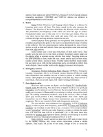
The results of the distance measurements are summarized in Figure 10. The readout
distance is defined as the distance where the signal power sinks below 80 % of the reference
signal, where 1x 9 dBi or 1x 18 dBi means that one reader antenna per channel with an
antenna gain of 9 dBi or 18 dBi is used, 2x 9 dBi or 2x 18 dBi means double antenna per
channel mode. In addition, some measurements have been performed using the averaging
ability of the system. This facility increases the readout range but at the cost of readout
speed. With a two antenna system using 18 dBi each and an averaging factor of 8 (8x av.), a
maximum readout range of about 6.5 m has been achieved.
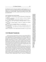
Figure 11 shows the readout range between RT and 300°C using a 9 dBi antenna in single
channel mode, for a single shot measurement. The measured read out range at RT was
taken as reference distance. At 300°C, the readout range decreases to 30 % of the original
range at RT. Due to physical effects, the attenuation of the transponder signal increases
with operating temperature. In the temperature range between RT and 300°C, the loss is
almost linearly 0.05 dB/µs °C. Roughly half of this value, 0.02 dB/µs°C [13], can be
ascribed to the change of the acoustic propagation attenuation of the crystals with
SAW Transponder – RFID for Extreme Conditions
311
temperature. The other half of the attenuation can be referred to the temperature
dependent frequency shift of the transducers and the transfer function of the transponder
antenna relative to the fixed ISM band.
Fig. 10. Read range for various antenna configurations and averaging factors.
Fig. 11. Read range depending on transponder temperature.