Novel Applications of the UWB Technologies Part 2 ppt
Bạn đang xem bản rút gọn của tài liệu. Xem và tải ngay bản đầy đủ của tài liệu tại đây (1.39 MB, 30 trang )
Multiband OFDM Modulation and Demodulation for Ultra Wideband Communications
17
The CSI is estimated from each of the CE sequences transmitted on that band. The LS CSI for
each equalized data is calculated from the received and stored CE sequences and given by
(19). It should be noted that CEr/CEs includes both phase and amplitude information, i.e.
the I and Q components of each frequency component of the sequences, whereas CSI is the
modulus of CEr/CEs and therefore is a scalar term. Moreover, no division is required in the
CSI calculation according to (18), where CE
r
is the received CE sequence, CE
s
is the priori
stored CE sequence, which means the divider can be avoided in the hardware
implementation, thus lowering the complexity of system implementation.
r
s
CE
CSI
CE
(19)
With the similarity of computing the channel estimation, taking the 6 CE sequences can create
the 6 averaging blocks of CSI for the non-hopping schemes. Hence, averaging those different
blocks of CSI can produce a more accurate CSI in the time invariant or slowly changing
channel with respect to the frame time. Again, subject to the mandatory mode, TFC=1 and
BG=1 is selected for the band hopping. The first block of CSI is averaged with the fourth block
of CSI while the second one is averaged with the fifth one, and the third one is averaged with
the sixth one. Then the new averaged CSI blocks are illustrated in Figure 15.
Fig. 15. Averaged CSI blocks allocation for TFC=1, BG=1
To avoid the cost of this CSI aided Viterbi decoder, the soft input of the decoding chain is
obtained from the multiplication of the demodulation soft output R
m
and its corresponding
CSI
k
, as described in (20). The receiver is arranged to modify the soft bits using the CSI, as
illustrated in Figure 16. The overall data reliability is obtained from directly scaling the soft
bit value by the corresponding CSI value. Therefore the reliability of received data is
maximized. What is of upmost interest is to apply the CSI as a demapping technique for the
MB-OFDM system at the higher data rates, where the DCM modulation scheme is used.
mm k
Softbit R CSI
(20)
where m is the index of the numbers of soft bit value depending on the modulation scheme;
k is the index into the 100 data subcarriers in an OFDM symbol.
Demapper
Soft Bit
Modifier
FFT
(
k
R
Y
Channel
Equalizer
Channel
Estimator
Modified
Soft Bits
CSI
m
R
Fig. 16. Demodulation exploiting CSI
1
CSI
2
CSI
3
CSI
4
CSI
5
CSI
6
CSI
1&4
CSI
2&5
CSI
3&6
CSI
1&4
CSI
2&5
CSI
3&6
CSI
Novel Applications of the UWB Technologies
18
4.2.2 Soft bit demapping
The DCM demapper shall demap two equalized complex numbers (I
R(k),
Q
R(k)
) and (I
R(k+50),
Q
R(k+50)
) that previously transmitted on two different subcarriers back to two related DCM
symbols by using the DCM mixing matrix. Then the DCM demapper outputs the
corresponding real part and imaginary part as a group of 4 soft bits, as described in (21)-
(24). However, demapping performance can remain the same without using the factor of
10 /5. The group of 4 soft bits applying two CSI values are from two corresponding data
subcarriers in an OFDM symbol, as described in (25)-(28).
() () ( 50)
()102 /5
gk Rk Rk
Soft b I I
(21)
()1 () ( 50)
()10 2 /5
gk Rk Rk
Soft b I I
(22)
()50 () ( 50)
()102 /5
gk Rk Rk
Soft b Q Q
(23)
()51 () ( 50)
()10 2 /5
gk Rk Rk
Soft b Q Q
(24)
() () ( 50) 50
()2 min ,
gk Rk Rk k k
Soft b I I CSI CSI
(25)
()1 () ( 50) 50
() 2 min,
gk Rk Rk k k
Soft b I I CSI CSI
(26)
()50 () ( 50) 50
()2 min,
gk Rk Rk k k
Soft b Q Q CSI CSI
(27)
()51 () ( 50) 50
() 2 min,
gk Rk Rk k k
Soft b Q Q CSI CSI
(28)
4.2.3 Maximum likelihood soft bit demapping
The more reliable soft bit values that are given to Viterbi decoder, the more accurately the
binary bits can be decoded. Maximum Likelihood (ML) offers finding parameters to obtain
the most probable emitted symbols (Oberg, 2001). The DCM symbols are transmitted at
different amplitudes and phases (I and Q values). The real part or the imaginary part in the
two DCM symbols (signal amplitude) is always fixed with data pairs being -3 and +1, -1 and
-3, +1 and +3, +3 and -1. In our case, the large probable soft bit value can be obtained from
the two received DCM symbols with an appropriate parameter θ, as described in (29)-(32).
The DCM symbol pair, y
R(k)
and y
R(k+50)
, is received from the channel equalization.
() () ( 50)
()2
gk Rk Rk
Soft b I I
(29)
()1 () ( 50)
() 2
gk Rk Rk
Soft b I I
(30)
()50 () ( 50)
()2
gk Rk Rk
Soft b Q Q
(31)
()51 () ( 50)
() 2
gk Rk Rk
Soft b Q Q
(32)
Multiband OFDM Modulation and Demodulation for Ultra Wideband Communications
19
To find the appropriate parameter θ, two conditions need to be satisfied.
a.
If perfect, I and Q values received are input to the DCM demapper, applying θ to
equations (29)-(32) to make the soft magnitude sufficiently large;
b.
A symbol in the DCM symbol pair is transmitted with a large magnitude I (or Q),
while another symbol in the DCM symbol pair is transmitted with a small magnitude I
(or Q). The signal with smaller power can be more easily corrupted. Suppose the small
magnitude I (or Q) in a DCM symbol is received as inverted, while the large
magnitude I (or Q) in another DCM symbol is received as uncorrupted. In this case, a
maximum θ is required to retain the sign of the soft bit value; otherwise using a larger
θ can make the sign of the soft bit value inverted, which causes errors for the soft bit
decoding.
θ is set to 1.5 as a threshold value according to the two conditions above. The ML soft bit
is generated with the appropriate factor and CSI aided technique as described in the
following:
() () ( 50) 50
()3 min ,
gk Rk Rk k k
Soft b I I CSI CSI
(33)
()1 () ( 50) 50
() 3 min,
gk Rk Rk k k
Soft b I I CSI CSI
(34)
()50 () ( 50) 50
()3 min,
gk Rk Rk k k
Soft b Q Q CSI CSI
(35)
()51 () ( 50) 50
() 3 min,
gk Rk Rk k k
Soft b Q Q CSI CSI
(36)
4.2.4 Log likelihood ratio demapping
As well as improving the symbol reliability at the input of the Viterbi decoder, Log
Likelihood Ratio (LLR) is another alternative demapping approach for the DCM. The
generic format of LLR equation can be expressed in (37). In our case, a LLR is calculated
from the received DCM symbols y
R(k)
and y
R(k+50)
. In addition, the LLR functions related to
the two 16-QAM like constellations are independent. Hence the LLR for a group of 4 bits
(b
g(k )
, b
g(k)+1
, b
g(k)+50
, b
g(k)+51
) is formed from combining the two independent LLR, as in (38)-
(41). σ
2
is noise variance associated with the channel.
lo
g
exp( ) exp( ) lo
g
exp( ) exp( )LLR AB XY
(37)
() ()
() ()
22
() () ( 50) ( 50)
()
22
11
50
22
() () ( 50) ( 50)
22
00
50
()log exp exp
log exp exp
gk gk
gk gk
Tk Rk Tk Rk
gk
bb
kk
Tk Rk Tk Rk
bb
kk
II I I
LLR b
II I I
(38)
Novel Applications of the UWB Technologies
20
()1 ()1
(()1
22
() () ( 50) ( 50)
()1
22
11
50
22
() () ( 50) ( 50)
22
0
50
()log exp exp
log exp exp
gk gk
gk gk
Tk Rk Tk Rk
gk
bb
kk
Tk Rk Tk Rk
bb
kk
II I I
LLR b
II I I
)1
0
(39)
()50 ()50
()50
22
() () ( 50) ( 50)
()50
22
11
50
22
() () ( 50) ( 50)
22
0
50
()log exp exp
log exp exp
gk gk
gk
Tk Rk Tk Rk
gk
bb
kk
Tk Rk Tk Rk
b
kk
QQ Q Q
LLR b
QQ Q Q
()50
0
gk
b
(40)
( ) 51 ( ) 51
()51
22
() () ( 50) ( 50)
()51
22
11
50
22
() () ( 50) ( 50)
22
0
50
()log exp exp
log exp exp
gk gk
gk
Tk Rk Tk Rk
gk
bb
kk
Tk Rk Tk Rk
b
kk
QQ Q Q
LLR b
QQ Q Q
()51
0
gk
b
(41)
For a Gaussian channel, the LLR can be approximated as two piecewise-linear functions
which depend on the amplitude of I/Q signals (Seguin, 2004). Furthermore, the maximum
LLR value can be approximated to be soft magnitude with the associated bit completely
depending on the amplitude of the I/Q signals. In our case, there are two bits associated
with each of the two 16-QAM like constellations completely relying on their soft
magnitude of the I/Q. The LLR functions related to these two bits from each constellation
are considered to be partially linear. Therefore some terms of these LLR functions are
approximated by soft magnitude, as in (42)-(45). The CSI is also used for LLR soft bit
values scaling. The noise variance is obtained from mapping the ratio of received symbol
and its average energy estimate has been taken into account to approximate the LLR
value.
()
()
2
(50) (50)
() ()
2
1
50
2
(50) (50)
2
0
50
()3 log exp
log exp
gk
gk
Tk Rk
gk Rk
b
k
Tk Rk
b
k
II
LLR b I
II
(42)
Multiband OFDM Modulation and Demodulation for Ultra Wideband Communications
21
()1
()1
2
() ()
()1
2
1
2
() ()
(50)
2
0
()log exp
log exp 3
gk
gk
Tk Rk
gk
b
k
Tk Rk
Rk
b
k
II
LLR b
II
I
(43)
()50
()50
2
(50) (50)
()50 ()
2
1
50
2
(50) (50)
2
0
50
()3log exp
log exp
gk
gk
Tk Rk
gk Rk
b
k
Tk Rk
b
k
LLR b Q
(44)
()51
()51
2
() ()
()51
2
1
2
() ()
(50)
2
0
()log exp
log exp 3
gk
gk
Tk Rk
gk
b
k
Tk Rk
Rk
b
k
LLR b
Q
(45)
Now the LLR functions have been simplified by approximating with a linear part, to solve
the non-linear part for the LLR function, the noise variance σ
2
needs to be estimated, which
generally requires the mean of the absolute value of the received symbol components (m, as
in (46)) and also estimates the average energy of the received symbol components (E, as in
(47)). The ratio of m
2
/E can be mapped to ratio α/m (α is signal amplitude, I or Q) and ratio
σ
2
/m. σ
2
can be determined from this mapping, but requiring large calculation in hardware
and computation simulation.
() ()
1
1
2
K
Rk Rk
k
mIQ
k
(46)
22
() ()
1
1
2
K
Rk Rk
k
EIQ
k
(47)
4.2.5 System performance for 480 Mb/s mode
The system is simulated at the data rate of 480 Mb/s in UWB channel model 1 (CM1). The
original MB-OFDM proposal settings of 2000 packets per simulation with a payload of 1024
octets each in the PSDU and 90
th
-percentile channel realization were followed. Strict
adherence to timing was used. A hopping characteristic of TFC=1 was used. A 6.6 dB noise
figure and a 2.5 dB implementation loss in the floating point system model were
incorporated. The guard interval diversity is also used in the simulation.
Novel Applications of the UWB Technologies
22
The system performance exploiting soft bit, ML soft bit, and LLR DCM demapping methods
with CSI as demapping enhancements were examined. From the simulation results shown
in Figure 17, LLR with CSI is better demapping method and can achieve 3.9 meters in CM1.
On closer examination for the performance at 8% PER, ML soft bit demapping method can
achieve 3.9 meters in CM1 as well. In this case it is reasonable to conclude that ML soft bit
demapping has same performance as LLR, but with slightly worse performance in shorter
distance transmission. Soft bit demapping with CSI can only achieve 3.4 meters at 8% PER
level in CM1. However soft bit or ML soft bit demapping method has lower computation
complexity and reduces hardware implementation cost. Therefore ML soft bit demapping
with CSI will be the best demapping method to implement hardware for ECMA-368.
The system performance in the 480 Mb/s mode was compared with current literature. It is
difficult to compare the system performance with all the literature because most of them did
not follow the conformance testing from WiMedia. This research used the simulation result
from MBOA-SIG proposal (Multiband OFDM Alliance, 2004) for comparison. By
implementing Kim’s LLR DCM demapping method (Kim, 2007) with this proposed CSI
further demapping technique, then the research will have the system performance using
Kim’s method for comparison. Figure 18 depicts the comparision for system performance
for 480 Mb/s mode in CM1, wherein a performance gain can be achieved by the proposed
LLR CSI method, while the system performance is 3.8 meters in MBOA-SIG proposal and
the sytem using Kim’s method. As can be seen, the proposed LLR CSI scheme performs the
best at 8% PER.
Fig. 17. Performance comparison for the proposed DCM demapping methods
Multiband OFDM Modulation and Demodulation for Ultra Wideband Communications
23
Fig. 18. Performance comparison for 480 Mb/s mode in CM1
4.3 Dual Circular 32-QAM
To enable the transport of high data rate UWB communications, ECMA-368 offers up to 480
Mb/s instantaneous bit rate to the MAC layer. However the maximum data rate of 480
Mb/s in a practical radio environment can not be achieved due to poor radio channel
conditions causing dropped packets unfortunately resulting in a lower throughput hence
need to retransmit the dropped packets. An alternative high data rate modulation scheme is
needed to allow effective 480 Mb/s performance.
Two 16-QAM-like constellation mappings are used in the DCM. Obviously if only one 16-
QAM-like constellation mapping is used for the modulation, this would result in less
reliability but twice the number of bits can be transmitted per subcarrier offering faster
throughput, which is from 640 Mb/s to 960 Mb/s comparing to DCM 320 Mb/s to 480 Mb/s
mode (see Table 3). However there is no successful link under multipath environments
(CM1 CM4) transmitting at 960 Mb/s or the system has poor performance only achieving
1.2 meters at 640 Mb/s. The simulation result will be shown in section 4.3.3. Hence 16-QAM
is not the ideal modulation scheme for the high data rate MB-OFDM system.
4.3.1 Dual Circular 32-QAM mapping
Since 16-QAM is not a suitable modulation scheme for the high data rate MB-OFDM system,
there is no need to consider higher order modulations, for instance 32-QAM, 64-QAM etc.
Therefore if a new modulation scheme is proposed to fit into the existing system, the new
modulation scheme comprising for an OFDM symbol shall not map the number of bits over
400 bits. Moreover, the new modulation scheme needs to be robust mapping 400 bits or less
with successful transmission in a multipath environment.
A Dual Circular (DC) 32-QAM modulator is proposed to use two 8-ary PSK-like
constellations mapping 5 bits into two symbols, which is basically derived from two QPSK
symbols mapping 4 bits and taken the bipolarity of the fifth bit to drive the two QPSK
Novel Applications of the UWB Technologies
24
constellations to two 8-ary PSK-like constellations. Within a group of 5 bits, the first and
second bit are mapped into one DC 32-QAM symbol, while the third and forth bit are
mapped into another DC 32-QAM symbol, and then the fifth bit is mapped into both DC 32-
QAM symbols offering diversity. 250 interleaved and coded bits are required to map by the
DC 32-QAM mapper onto 100 data subcarriers in an OFDM symbol, hence increasing the
system throughput to 600 Mb/s comparing to the DCM 480 Mb/s mode (see Table 3).
Figure 19 depicts the proposed DC 32-QAM modulator as an alternative modulation scheme
that fits into the existing PSDU encoding process with the objective to map more
information bits onto an OFDM symbol. After the bit interleaving, 1500 coded and
interleaved bits are required to divide into groups of 250 bits and then further grouped into
50 groups of 5 reordering bits. Each group of 5 bits is represented as (b
g(k)
, b
g(k)+50
, b
g(k)+51
,
b
g(k)+100
, b
g(k)+101
), where k
[0…49] and
2 024
250 2549
kk
gk
kk
(48)
Four bits (b
g(k)+50
, b
g(k)+51
, b
g(k)+100
, b
g(k)+101
) are mapped across two QPSK symbols (x
g(k)
+jx
g(k)+50
),
(x
g(k)+1
+jx
g(k)+51
) as in (49). Those two bits pairs are not in consecutive order within the bit
streams. b
g(k)+50
and b
g(k)+100
are mapped to one QPSK symbol while b
g(k)+51
and b
g(k)+101
are
mapped to another, which aids to achieve further bit interleaving against burst errors.
Data
Rate
(Mb/s)
Modulation
Coding
Rate
(R)
Frequency
Domain
Spreading
Time
Domain
Spreading
Coded Bits /
6 OFDM
symbol(N
CBP6S
)
53.3 QPSK 1/3 YES YES 300
80 QPSK 1/2 YES YES 300
106.7 QPSK 1/3 NO YES 600
160 QPSK 1/2 NO YES 600
200 QPSK 5/8 NO YES 600
320 DCM 1/2 NO NO 1200
400 DCM 5/8 NO NO 1200
480 DCM 3/4 NO NO 1200
600
DC 32-
QAM
3/4 NO NO 1500
640 16-QAM 1/2 NO NO 2400
960 16-QAM 3/4 NO NO 2400
Table 3. PSDU rate-dependent parameters
DC 32-
QAM
Ma
pp
e
r
Bit
Interleaver
PSDU
Convolutional
Encoder /
Puncture
r
IFFT
)(kT
Y
Scrambler
Fig. 19. PSDU Encoding process with DC 32-QAM
Multiband OFDM Modulation and Demodulation for Ultra Wideband Communications
25
() ()50 ()50 ()100
( ) 1 ( ) 51 ( ) 51 ( ) 101
(2 1) (2 1)
(2 1) (2 1)
gk gk gk gk
gk gk gk gk
xjx b jb
xjx b jb
(49)
Then these two QPSK symbols are mapped into two DC 32-QAM symbols (y
T(k)
, y
T(k+50)
)
depending on value of bit b
g(k)
as in (50)-(52), where K
MOD
= 1/
6.175
as the normalization
factor. Each DC 32-QAM symbol in the constellation mapping has equal decision region for
each bit, as illustrated in Figure 20. The DCM symbols having two 16-QAM-like
constellations do not have fixed amplitude. Thus the DCM will worsen the Peak to Average
Power Ratio (PAPR) of the OFDM signals, resulting in more impact to the Automatic Gain
Control (AGC) and ADC. In contract, the constellation points are positioned in circular loci
to offer constant power for each DC 32-QAM symbol, which is of great benefit to the AGC
and ADC.
() ()50
()
(50) ()1 ()51
gk gk
Tk
MOD
Tk gk gk
xjx
y
K
yxjx
(50)
where
()
()
,0
1
2.275 , 1
gk
gk
b
b
(51)
()
()
,0
2.275
1, 1
gk
gk
b
b
(52)
-d
1
d
1
d
2
b
g(k),
b
g(k)+50,
b
g(k)+100
011
001
111
101
110
100
000
010
-d
2
d
1
d
2
-d
1
-d
2
d
1
=1
d
2
=2.275
I
T(k)
Q
T
(
k
)
-d
1
d
1
d
2
b
g(k),
b
g(k)+51,
b
g(k)+101
111
101
011
001
010
000
100
110
-d
2
d
1
d
2
-d
1
-d
2
d
1
=1
d
2
=2.275
I
T(k+50)
Q
T
(k
+50
)
(a) (b)
Fig. 20. DC 32-QAM constellation mapping: (a) mapping for y
T(k)
; (b) mapping for y
T(k+50)
The two resulting DC 32-QAM symbols (y
(k)
, y
(k+50)
) are allocated into two individual OFDM
data subcarriers with 50 subcarriers separation to achieve frequency diversity. An OFDM
symbol is formed from the 128 point IFFT block requiring 100 DC 32-QAM symbols. Each
OFDM subcarrier occupies a bandwidth of about 4 MHz, therefore the bandwidth between
Novel Applications of the UWB Technologies
26
the two individual OFDM data subcarriers related to the two complex numbers (I
(k)
, Q
(k)
)
and (I
(k+50)
, Q
(k+50)
) is at least 200 MHz, which offers a frequency diversity gain against
channel deep fading. This will benefit for recovering the five information bits mapped
across the two DC 32-QAM symbols. Figure 21 depicts the DC 32-QAM mapping process.
IFFT
QPSK
50 subcarriers
separation in an
OFDM symbol
b
g(k)+51
b
g(k)+101
QPSK
x
g(k)
+ jx
g(k)+50
x
g(k)+1
+jx
g(k)+51
y
(k)
y
(k+50)
b
g(k)
Dual
Circluar
32QAM
Mapper
b
g(k)+50
b
g(k)+100
Fig. 21. DC 32-QAM mapping process
4.3.2 DC 32-QAM demapping
The proposed DC 32-QAM utilizes soft bit demapping to demap two equalized complex
numbers previously transmitted on different data subcarriers into a subgroup of 5 soft bits,
and then outputs groups of 250 soft bits in sequential order. The demapper is proposed to
use the DC 32-QAM demapper, and other functional blocks are remained. The demapped
and deinterleaved soft bits are input to Viterbi decoder to recover the original bit streams.
Each soft bit value of b
g(k)+50
, b
g(k)+51
, b
g(k)+100
and b
g(k)+101
depend on the soft bit magnitude of
the I/Q completely. In addition, each soft bit can be demapped from its associated (I
R(k)
,
Q
(k)
) and (I
R(k+50)
, Q
R(k+50)
) independently. Furthermore, the demapping performance can
remain without using the factor 1/ K
MOD
. Hence the soft bit values for b
g(k)+50
, b
g(k)+51
, b
g(k)+100
and b
g(k)+101
are given by the following.
()50 ()
()
g
kRk
Soft b I
(53)
()51 ( 50)
()
gk Rk
Soft b I
(54)
()100 ()
()
g
kRk
Soft b Q
(55)
()101 ( 50)
()
gk Rk
Soft b Q
(56)
To demap b
g(k)
in the constellation for y
R(k)
, the demapped information bit is considered to
be ‘1’ if the received symbol is close to the constellation point along with I axis, otherwise it
is ‘0’ if close to the constellation point along with Q axis. However, to demap b
g(k)
in the
Multiband OFDM Modulation and Demodulation for Ultra Wideband Communications
27
constellation for y
R(k+50)
, the demapped information bit is considered to be ‘0’ if the received
symbol is close to the constellation point along with I axis, otherwise it is ‘1’ if close to the
constellation point along with Q axis. Figure 22 depicts Euclidean distances for a possible
received DC 32-QAM symbol pair with region for b
g(k)
. Since the bit regions of b
g(k)
in the
two constellation mapping are different, the associated I and Q value from y
R(k)
and y
R(k+50)
cannot be simply combined. Hence the Euclidean symbol distance for each received symbol
in the associated constellation mapping is calculated first, as in (57)-(60). Then the two
Euclidean symbol distances are summed together as a soft bit value for b
g(k)
, as in (61).
b
g(k)
0
0
1
1
1
1
0
0
Q
T
(
k
)
I
T
(
k
)
L
1
L
2
Y
R(k)
d
1
d
2
-d
1
-d
2
-d
1
-d
2
d
1
d
2
b
g(k)
1
1
0
0
0
0
1
1
Q
T(k+50)
L
1
L
2
Y
R(k+50)
d
1
d
2
-d
1
-d
2
-d
1
-d
2
d
1
d
2
I
T(k+50)
Fig. 22. Symbol distances for a possible received symbol pair y
R(k)
and y
R(k+50)
with decision
region for b
g(k)
22
() ()
11 2
Rk Rk
LIdQd
(57)
22
() ()
22 1
Rk Rk
LIdQd
(58)
22
( 50) ( 50)
31 2
Rk Rk
LI dQ d
(59)
22
(50) (50)
42 1
Rk Rk
LI dQ d
(60)
()
1
() 1234
2
gk
So
f
tb L L L L (61)
The proposed CSI aided scheme coupled with the band hopping information maximizes the
DCM soft demapping performance. b
g(k)
mapped to two DC 32-QAM symbols are mapped
onto two OFDM data subcarriers resulting in two CSI from the two associated data
subcarriers. If a smaller or larger CSI value is chosen as a reliable scale term, it causes
inequality of signal power for the different OFDM data subcarriers. The averaging CSI is
adopted for b
g(k)
. Therefore the soft bits incorporated with CSI for the DC 32-QAM
demapping are given by the following:
Novel Applications of the UWB Technologies
28
50
()
1234
()
22
kk
gk
CSI CSI
LLLL
Soft b
(62)
()50 ()
()
g
kRkk
Soft b I CSI
(63)
( ) 51 ( 50) 50
()
gk Rk k
Soft b I CSI
(64)
()100 ()
()
g
kRkk
Soft b Q CSI
(65)
()101 ( 50) 50
()
gk Rk k
Soft b Q CSI
(66)
4.3.3 System performance comparison for 16-QAM, DC 32-QAM and DCM
The system simulation setting is same as in section 4.2.4. To compare 16-QAM, DC 32-QAM
and DCM performance, the system is set to the same configuration with the same coding
rate. All the modulation schemes for the comparison use the best demapping solutions with
CSI aided demapping scheme as presented in this thesis. While changing the modulation
scheme and the associated bit interleaver, the system throughput can be increased to 600
Mb/s and 960 Mb/s by DC 32-QAM and 16-QAM respectively, while the DCM performs
480 Mb/s. As shown in Figure 23, there is no successful link if the system is operated with
16-QAM at the data rate of 960 Mb/s. Alternatively lowering the data rate to 640 Mb/s by
changing the coding scheme (Table 3), the system performance is only 1.2 meters. However,
implementing the DC 32-QAM scheme offers 3.2 meters at 600 Mb/s while the existing
system using DCM can be achieved 3.9 meters at 480 Mb/s. The effective 600 Mb/s
performance in practical multipath environment with moderate packet loss can offer an
effective data rate at 480 Mb/s.
Fig. 23. System performance comparison for 16-QAM, DC 32-QAM and DCM
Multiband OFDM Modulation and Demodulation for Ultra Wideband Communications
29
5. Conclusions
WiMedia Alliance working with ECMA established MB-OFDM UWB radio platform as the
global UWB standard, ECMA-368. It is an important part to consumer electronics and the
users’ experience of these products. Since the standard has been set for the transmitter,
optimization of the receiver becomes paramount to maximize the MB-OFDM system
performance. Furthermore, the solutions of improving the MB-OFDM need to be cost-
effective for implementing the low power and high performance device.
OFDM modulation is the important part for the multicarrier system. The proposed dual
QPSK soft demapper exploiting TDS and guard interval diversity improved the system
performance with requiring no overhead for ECMA-368. Three DCM demapping methods
have been described and developed, which are soft bit demapping, ML soft bit
demapping and LLR demapping methods. A CSI aided scheme coupled with the band
hopping information maximized the DCM demapping performance, thus improving the
system performance. Based on the QPSK and DCM, a cost-effective and high performance
modulation scheme (termed DC 32-QAM) that fits within the configuration of current
standard offering high rate USB throughput (480 Mb/s) with a moderate level of dropped
packets, and can even offer a faster throughput for comparable propagation conditions.
The contribution of this research can enable the UWB technology and help to ensure its
success.
Hardware implementation at FPGA need solutions for ever increasing demands on system
clock rates, silicon performance and long verification times etc. Not only logic and design
size minimization, but also architecture solutions will be the challenge for the further
research to handle large amounts of data through a fast UWB wireless connection.
6. References
aRenarti Semiconductor (2007). MB-OFDM UWB PHY: Baseband Processor (BBP), August
2007, Available from
Batra, A.; et al. (2004). Multi-band OFDM physical layer proposal for IEEE 802.15 task group
3a, IEEE standard proposal P802.15-03, March 2004
Batra, A.; Balakrishnan, J.; Aiello, G.; Foerster, J. & Dabak, A. (2004). Design of a multiband
OFDM system for realistic UWB channel environments, IEEE Transactions on
Microwave Theory and Techniques, Vol.52, No.9, (September 2004), pp 2123-2138,
ISSN: 0018-9480
ECMA-368 (2008). High rate ultra wideband PHY and MAC standard (3rd Edition), ECMA
International, December 2008
Ellis, J.; Siwiak, K. & Roberts, R. (2002). TG3a Technical Requirements, IEEE P802.15-03/030-
SG3a, December 2002
FCC (February 2002). New public safety applications and broadband internet access among
uses envisaged by FCC authorization of ultra-wideband technology, press released
February 14, 2002
FCC (April 2002). Revision of Part 15 of the Commissions Rules Regarding Ultra-
Wideband Transmission Systems. ET Docket 98-153, FCC 02-48; Released: April
22, 2002
Novel Applications of the UWB Technologies
30
Fisher, R.; et al (2005). DS-UWB Physical Layer Submission to 802.15 Task Group 3a, IEEE
standard proposal IEEE P802.15-04/0137r4, January 2005
Foerster, J. (2003). Channel Modeling Sub-committee Report Final, IEEE P802.15-02/490-
SG3a. February 7, 2003
Kim, Y. (2007). Dual Carrier Modulation (DCM) demapping method and demapper,
European Patent Application, EP1858215A1, November 21, 2007
Li, W.; Wang, Z.; Yan, Y. & Tomisawa, M. (2005). An efficient low-cost LS equalization in
COFDM based UWB systems by utilizing channel-state-information (CSI), IEEE
62nd Vehicular Technology Conference, Vol. 4, pp. 67-71, ISSN 1090-3038, Dallas,
Texas, USA, September 2005,
Multiband OFDM Alliance (2004). MultiBand OFDM Physical Layer Proposal for IEEE
802.15.3a, IEEE P802.15 Working Group for Wireless Personal Area Networks (WPANs).
September 2004
Oberg, T. (2001). Modulation, Detection and Coding, John Wiley & Sons, ISBN 0471497665,
Chichester, England
Proakis, J. G. (2001). Digital Communications (Fourth edition), McGraw-Hill, ISBN 0072321113,
New York, USA
Seguin, F.; Lahuec, Lebert, C. J.; Arzel, M. & Jezequel, M. (2004). Analogue 16-QAM
demodulator, IEE Electronics Letters, Vol.40, No.18, (September 2004), pp.1138-1140,
ISSN: 0013-5194
USB Implementers forum (2005). Wireless Universal Serial Bus Specification, Revision 1.0,
May 12, 2005
0
Orthogonal Pulse-Based Modulation Schemes for
Time Hopping Ultra Wideband Radio Systems
Sudhan Majhi
1
and Youssef Nasser
2
1
Electrical and Electronic Engineering, Nanyang Technological University
2
Faculty of Engineering and Architecture, American University of Beirut
1
Singapore
2
Lebanon
1. Introduction
Ultra wideband (UWB) radio is a promising technology for short range wireless
communications. It can be used for both high rate and low rate transmissions. High data
rate can be achieved by using multiband (MB)-UWB approach whereas low data rate with
robust system performance can be obtained by employing time hopping (TH)-UWB radio
systems Majhi et al. (2006); Win & Scholtz (1998a). Nowadays, applications of UWB are
spreading to various fields such as vehicle communications, wireless sensor networks, ad
hoc wireless networks, and controller area networks. The most of the systems require low
to moderate (1 kbs-100 mbs) data rates with an acceptable implementation cost. However,
due to the presence of fast Fourier transform (FFT) and inverse FFT (IFFT), MB-UWB may
not be a cost effective procedure for low data rate systems. Therefore, one needs an efficient
system which adaptively changes the data rate from low to moderate with robust system
performance. TH-UWB with OOK-PSM modulation provides low data rate with robust
system performance Majhi, Madhukumar, Premkumar & Richardson (2008). However, it is
possible to scale the TH-UWB radio system for low to moderate data rates by incorporating
higher level modulation schemes with an adaptive method.
For TH-UWB systems, various M-ary modulation schemes such as pulse position modulation
(PPM), pulse amplitude modulation (PAM), pulse shape modulation (PSM), and their
combined forms have been proposed to improve data rates and system performance with low
complexities Bin et al. (2003); Durisi & Benedetto (2003); Ghavami et al. (2002); Michell et al.
(2003); Usuda et al. (2004). However, due to the increase of inter symbol interference (ISI)
in the presence of multipath channel, M-ary PPM or M-ary orthogonal PPM (OPPM) are
not effective for TH-UWB systems with RAKE reception when M is high Foerster (2003);
Win & Scholtz (1998b). High-level M-ary PAM is rarely used in short range and low power
consumption communications systems Guvenc & Arslan (2003). This is because that the
Euclidian distances between constellations become small with increase in M.Duetoits
robustness against ISI and multiple access interference (MAI), pulse-based modulation such
as PSM has become an interesting research topic in TH-UWB, direct sequence UWB (DS-UWB)
and transmitted reference UWB (TR-UWB) radio systems Chu & Murch (2005); de Abrue et al.
(2003); Gezici et al. (2006); Hwang et al. (2007); Kim & Womack (2007); Parr et al. (2003).
However, high-level M-ary PSM cannot be used due to the limited auto correlation properties
2
2 Name of the Book
of higher order orthogonal pulses. Moreover, its system complexity increases linearly with
order of pulse waveform Gezici & Kobayashi (2005); Harada et al. (2004).
To deal with these challenges, combined modulation schemes such as M-ary biorthogonal
PSM (BPSM), PPM-PSM, BPSK-PSM and OOK-PSM have been provided for M-ary
TH-UWB systems Hu & Zheng (2005); Majhi, Madhukumar & Premkumar (2007);
Majhi, Madhukumar, Premkumar & Chin (2007b); Michell et al. (2003); Usuda et al. (2004).
However, M-ary BPSM still requires M/2 orthogonal pulses to transmit the signal. To
improve system performance, PPM-PSM requires orthogonal coded modulation and
memory at the receiver to maintain orthogonalities among the constellation vectors
Mitchell & Kohno (2004). In the presence of multipath channel, BPSK-PSM and
OOK-PSM cannot be used for higher level modulation scheme for higher data rates
Majhi, Madhukumar, Premkumar & Chin (2007b); Usuda et al. (2004).
In order to address these problems, a combined modulation scheme (OPPM-BPSM) for
TH-UWB systems was provided by the first author of this chapter to increase system data rate
with good system performance Majhi et al. (2011). The proposed scheme was a combination of
orthogonal PPM (OPPM) and BPSM modulation. In this chapter, we provide TH-UWB system
design based on orthogonal pulse waveform. To show the robustness of orthogonal pulse
waveform for TH-UWB systems we have provided performance analysis, capacity analysis
and power spectral analysis of various orthogonal pulse based modulation schemes.
The rest of the chapter is organized as follows: section 2 describes used orthogonal pulses
and its various modulation forms. Section 3 discusses system performance of OPPM-BPSM
modulation schemes and its various interference issues. Section 4 provides the system
capacity of TH-UWB systems for several orthogonal pulse based modulation schemes. Section
5 provides power spectral analysis of orthogonal pulse based modulation scheme of TH-UWB
systems. Section 6 is provided for the simulation results. Section 7 provides the summary of
chapter.
2. System model for TH-UWB
One of the essential functions in TH-UWB systems is the representation of a message symbol
by a short duration pulse waveform for signal transmission through air de Abrue & Kohno
(2003); Hu & Beaulieu (2004). The pulse waveform is an important design consideration
which can affect UWB system performance considerably. The successful deployment of high
data rate indoor TH-UWB systems strongly depends on the development of pulse waveforms
and modulation schemes. Because of the short pulse waveforms, UWB is capable of providing
high data rates for short range wireless communication. The chapter describes orthogonal
pulse based TH-UWB system.
2.1 Orthogonal pulses
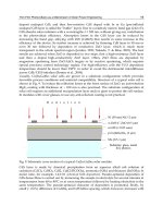
The commonly used orthogonal pulses for PSM modulation scheme are modified Hermite
pulses (MHPs)Ghavami et al. (2002), Prolate spheroidal wave functions (PSWFs) Usuda et al.
(2004), Battle-Lemarie wavelet orthogonal function Kim et al. (2005), and Haar wavelet
orthogonal function Zhang & Zhou (2005). In this chapter all the analysis has been
done based on MHPs and PSWFs. The system performance depends on autocorrelation
and crosscorrelation properties. In addition, MAI is also reduced considerably by
using crosscorrelation properties of orthogonal pulses. The time and frequency domain
representation of MHPs are given in Fig. 1.
32
Novel Applications of the UWB Technologies
Orthogonal Pulse-Based Modulation Schemes for Time Hopping Ultra Wideband Radio Systems 3
0 2 4 6 8 10 12
x 10
9
−400
−350
−300
−250
−200
−150
−100
−50
0
Frequency [Hz]
Amplitude
−10 −5 0 5 10
−1
−0.5
0
0.5
1
Time [ns]
Amplitude
n=0
n=1
n=2
n=0
n=1
n=2
Fig. 1. Time and frequency (logarithmic plot) domains representation of modified Hermite
pulses (MHPs).
33
Orthogonal Pulse-Based Modulation Schemes for Time Hopping Ultra Wideband Radio Systems
4 Name of the Book
2.2 M-ary Pulse Shape Modulation (PSM)
In pulse shape modulation, a set of symbols is assigned by a set of orthogonal pulses which
are orthonormal. The M-ary signal set for PSM can be written as
s
(k)
(t)=
∞
∑
j=−∞
E
(k)
tx
w
(k)
(
j/N
s
%M)
(t − jT
f
−c
(k)
j
T
c
) (1)
where
{w
0
(t), w
1
(t), ···, w
M −1
(t)} is a set of orthogonal pulses and in general w
i
(t)⊥w
l
(t)=
0fori = l and 1 for i = l in normalized form. M correlators and corresponding orthogonal
pulses are used as a reference signal to detect M-ary signal at the receiver Usuda et al.
(2004)Kim et al. (2005). Any mutually orthonormal pulses can be used for this modulation
scheme.
2.3 M-ary Biorthogonal PSM
Biorthogonal PSM (BPSM) modulation is similar to BPM scheme, the only difference is that it
is used for M-ary signaling . M-ary BPSM uses M/2 orthogonal pulses in the transmitter and
M/2 correlators in the receiver to transmit all M possible symbols. The number of correlators
or matched filters used in this scheme drops to half of those used in M-ary PSM scheme, thus
reducing complexity of TH-UWB systems. An M-ary BPSM modulation has been proposed
in Wen & Guoxin (2005). The output of an M-ary BPSM can be a signal with M/2 possible
pulse shapes which are biorthogonal. Orthogonal pulse shapes are represented as follows:
w
0
(t), w
1
(t), , w
M /2−1
(t). The negative ones are defined as w
i+M/2
(t)=−w
i
(t),where
i
= 0, 1, , M/2 −1.
BPSM gives high data rate and makes it easier to map symbols into pulse waveforms. It has
high power efficiency due to pulse polarity. However, similar to BPM scheme, it also requires
two transmitters to generate BPSM signal. Maintaining bi-phase of orthogonal pulses is a
challenging task. On the other hand, due to limitation of the possible number of orthogonal
pulses it cannot be used for higher level modulation schemes.
2.4 M-ary OPPM-BPSM
OPPM-BPSM scheme is a combination of orthogonal PPM and biorthogonal PSM
(OPPM-BPSM). In order to transmit M symbols, one has to use L orthogonal pulse positions
and N biorthogonal pulses where M
= 2
k
, L = 2
l
, N = 2
k−l−1
, k > 1and0 ≤ l ≤
k − 1. Antipodal pulses are chosen to smooth the PSD of TH-UWB signal and to improve
its coexistence ability with NB systems without any degradation in system performance
Majhi, Madhukumar & Ye (2007). These biorthogonal pulses reduce the number of correlators
in the receiver. Further, the system complexity is reduced by half when compared with
a scheme that uses a combination of L pulse positions and N orthogonal pulses Kim et al.
(2005). By changing the number of pulse positions and orthogonal pulses, one can construct
a wide variety of symbols. For example, M-ary BPPM scheme can be constructed by using
M/2 pulse positions and one biorthogonal pulse waveform, and M-ary BPSM scheme can be
constructed by using one pulse position and M/2 biorthogonal pulses Wen & Guoxin (2005);
Zhang & Gulliver (2005a). OPPM-BPSM scheme ensures relatively constant power envelope
for transmitted symbol irrespective of the number of pulse positions and biorthogonal pulses.
This multidimensional scheme increases the Euclidean distance of the transmitted signal, so
power efficiency increases without affecting signal bandwidth Ramseier & Schlegel (1993).
Since each position is able to transmit multiple orthogonal pulses, it does not require longer
chip duration as well as longer time frame compared to M-ary OPPM or M-ary BPPM
34
Novel Applications of the UWB Technologies
Orthogonal Pulse-Based Modulation Schemes for Time Hopping Ultra Wideband Radio Systems 5
schemes. Theoretically, N × L correlators are required in the receiver for M-ary OPPM-BPSM
scheme, however, only N correlators with L delay units are sufficient to receive the signal.
These delays can be implemented through software which reduces hardware complexity of
M-ary OPPM-BPSM scheme for N
< M.
3. Performance of M-ary OPPM-BPSM
The system performance of the orthogonal pulse based modulation scheme decreases in
the presence of multipath channel. The performance of OPPM-BPSM scheme is evaluated
using the UWB multipath channel model based on the indoor channel measurement in
the 2-8 GHz frequency band accepted by the IEEE802.15.3a study group Foerster (2003);
Saleh & Valenzuela (1987). For simplicity, it is also assumed that signal is transmitted by using
i
th
(0 ≤ i ≤ N −1) order pulse in the q
th
(0 ≤ q ≤ L −1) pulse position. Therefore the signal
in Majhi, Madhukumar, Premkumar & Chin (2007a) can be rewritten as
s
(k)
iq
(t)=
∑
j
E
(k)
tx
d
(k)
m
w
(k)
i
(t −jT
f
−c
(k)
j
T
c
−δ
(k)
q
) (2)
where d
m
∈{−1, 1}.IfthereareN
u
users and each experiences a different channel model, the
simplified received signal can be expressed as
r
(t)=
N
u
∑
k=1
L
p
∑
l=1
α
(k)
l
s
(k)
iq
(t − τ
(k)
l
)+n(t) (3)
where τ
(k)
l
is the delay of path of k
th
user which takes values in the continuous time-invariant
model, α
(k)
l
is the l
th
path gain of k
th
user, and L
p
is the maximum number of paths among
the users. It is assumed that the reference RAKE receiver is synchronized i.e. τ
(1)
l
= 0forl
th
RAKE finger of user 1. The receiver structure with RAKE fingers is shown in Fig.2. To receive
the symbols, receiver requires L bank of correlators based on the L positions and each bank
of correlators contains N correlators based on the order of orthogonal pulse. Further, each
correlator contains RAKE fingers based on the number of estimated paths. The delay of the
paths and fading are done by channel estimation.
The reference signal in correlator of i
th
order pulse and q
th
pulse position of user 1 can be
expressed as
φ
(1)
iq
(t)=
N
s
−1
∑
j=0
v
(1)
i
(t − jT
f
−c
(1)
j
T
c
−δ
(1)
q
) (4)
where N
s
is the number of pulse repetition interval for a symbol and
v
(1)
i
(t)=
L
p
∑
p=1
α
(1)
p
w
(1)
i
(t − τ
(1)
p
) (5)
35
Orthogonal Pulse-Based Modulation Schemes for Time Hopping Ultra Wideband Radio Systems
6 Name of the Book
r(t)
(b)
w
i
(t-
Lp
)
z
i0
Channel estimator Weight estimator
w
i
(t-
w
i
(t-
. . .
Path selection
Lp
³
dt
³
dt
³
dt
M-ary
symbol
Sign decision
arg max
(a)
z
00
Correlator for 0
th
order pulse
Correlator for 1
st
order pulse
Correlator for (N-1)
th
order pulse
. . .
z
10
z
(N-1)0
Correlator bank for 0
th
position
Correlator bank for 1
st
position
Correlator bank for (L-1)
th
position
r(t)
Fig. 2. Receiver structure for the OPPM-BPSM scheme (a) Block diagram for bank of
correlators for the different pulse position and different order of orthogonal pulses. (b) Block
diagram of correlators for 0
th
pulse position and i
th
(i = 0, 1, . . . , N −1) order pulse which
contains L
p
RAKE fingers for different delays and different weights
36
Novel Applications of the UWB Technologies
Orthogonal Pulse-Based Modulation Schemes for Time Hopping Ultra Wideband Radio Systems 7
3.1 Decision st atistics
At the receiver, the received signal, indicated as a useful signal, is corrupted by mainly three
additive noise components: ISI noise generated due to multipath components, MAI due to
presence of multiple users, and thermal noise generated in receiver antenna and receiver
circuitry. The problem of receiver design can thus be stated as follows: Finding a good, when
possible optimal, way for extracting a useful signal from the received signal. Solving the
general problem is a complicated task that leads to complex receiver structures and requires
good modeling of noise components. It is assumed that the receiver has perfect channel
estimation and uses partial RAKE combining. At sample time t
=(j + 1)T
f
,thecombined
output of first L
p
paths of the correlator for i
th
order pulse and for q
th
pulse position can be
written as Jia & Kim (2005); Jiang et al. (2005)
z
(1)
iq
=
(j+1)T
f
jT
f
r(t)φ
(1)
iq
(t)dt
= S
(1)
iq
+ ISI
(1)
iq
+ MAI
(1)
iq
+ N
(1)
iq
(6)
where S
(1)
iq
is the desired signal, ISI
(1)
iq
is the ISI term, MAI
(1)
iq
is the MAI term and N
(1)
iq
is
the AWGN component of user 1 in the correlator of i
th
order pulse and q
th
pulse position.
In order to improve detector performance of the system, effects of ISI and MAI have to be
canceled before a symbol decision is made. In communication systems, decision feedback
equalizers are commonly employed for this purpose. The main idea behind decision feedback
equalization is that once a data symbol has been detected, the interference induces on
the following symbols is estimated and subtracted out before the detection of subsequent
symbols. Therefore, knowledge of the desired signal and interference noise is required to
make correct decision. Gaussian approximation (GA) is not an appropriate method for finding
the interference noise when a few multiple users are present in the system, However, due to
its simplicity in the presence of multipath fading, this work assumes GA for the mathematical
analysis for different noise terms Giorgetti & Chiani (2005).
3.2 Desired signal energy
The transmitted signal propagates in a multipath channel. To collect these multipath
components, each correlator contains several RAKE fingers with different delays and weights.
The desired multipath components are correlated with corresponding RAKE fingers, and
some of these received energy are the desired or useful signal. In realistic scenarios it is
assumed that pulses are orthogonal in a synchronized system. Therefore, the desired signal
can be written as Majhi, Madhukumar, Premkumar & Chin (2007a)
S
(1)
iq
=
E
(1)
tr
d
(1)
m
N
s
L
p
∑
p=1
α
(1)
p
2
.(7)
It is observed that the received energy in the multipath channel increases with increase in the
number of RAKE fingers in the correlators, and this improves system performance. However,
large number of RAKE fingers increases the system complexity and channel estimation error.
Therefore, a minimum number of RAKE finger is used with considerable system performance.
Since d
(1)
m
∈{±1}, the constellation distance in OPPM-BPSM is far from those in OOK-PSM
scheme, which results in better system performance than that in OOK-PSM scheme.
37
Orthogonal Pulse-Based Modulation Schemes for Time Hopping Ultra Wideband Radio Systems
8 Name of the Book
3.3 Inter Symbol Interference (ISI)
In the reality, channel is not perfectly estimated, and each path is not synchronized. So the
decision variable is affected by other unexpected signals such as ISI. It occurs when multipath
components are not received by their corresponding RAKE fingers, these are received by other
RAKE fingers which have different weights and delays. The ISI noise of user 1 can be as
Majhi, Madhukumar, Premkumar & Chin (2007a)
σ
2
ISI
= E
(1)
tr
N
s
T
−1
f
L
p
∑
p=1
L
p
∑
l=1
L
p
∑
p
=1
p
=p
L
p
∑
l
=1
l
=l
α
(1)
p
α
(1)
l
α
(1)
p
α
(1)
l
X(Δ) (8)
where X
(Δ) is the correlation function and Δ is the delay parameter detail given in
Majhi, Madhukumar, Premkumar & Chin (2007a). It is observed that ISI is not reduced by
orthogonal pulses and their modulation schemes. It depends on channel estimation and
its delay spread. The channel delay spread cannot be controlled by modulation schemes or
system design. The ISI can be reduced by increasing the duration of pulse repetition interval,
which affects system data rates. On the other hand, duration of pulse repetition interval can
be shorter when several orthogonal pulses are used in one pulse position but it reduces the
system performance. This is one of many practical limitations for higher data rate systems
with good system performance.
3.4 Multiple Access Interference (MAI)
In multiple access systems, several users transmit signals over the same channel. Pulses
originating in other transmission links may interfere with pulses belonging to a reference
transmission giving rise to MAI. The MAI noise of user 1 from N
u
− 1 users can be written
from Majhi, Madhukumar, Premkumar & Chin (2007a) as
σ
2
MAI
= N
s
T
−1
f
N
u
∑
k=2
E
(k)
tr
L
p
∑
p=1
L
p
∑
l=1
L
p
∑
p
=1
L
p
∑
l
=1
α
(1)
p
α
(k)
l
α
(1)
p
α
(k)
l
Y(Δ
) (9)
where Y
(Δ
) is also a correlation function and Δ
is the delay parameter. The cross correlation
value is smaller than the auto correlation values in both synchronous and asynchronous
systems. It is observed that MAI depends on correlation properties of orthogonal pulses and
number of users in the system. MAI is the sum of interference of one user from all the other
users. When all the users use the same set of orthogonal pulses MAI is the sum of expectation
of the product of auto correlation and cross correlation. In the conventional system this is
expectation of product of auto correlation. Due to the presence of cross correlation term, MAI
is reduced. However, when all the users use a different subset of orthogonal pulses, MAI
is the sum of expectation of product of cross correlation which is the extreme case for better
system performance.
3.5 P erformance analysis
It is assumed that the correlator output z
iq
of i
th
order pulse and q
th
pulse position is larger
than the other M/2
−1 correlator outputs. As discussed before, each output is corrupted by
noise and the total noise at each correlator can be defined as σ
2
ISI
+ σ
2
MAI
+ σ
2
N
where σ
2
N
is
AWGN. The corresponding average probability of a correct decision in the presence of ISI and
38
Novel Applications of the UWB Technologies
Orthogonal Pulse-Based Modulation Schemes for Time Hopping Ultra Wideband Radio Systems 9
MAI can be expressed as Proakis (2001); Zhang & Gulliver (2005a)
P
c
=
∞
0
1
√
2π
z
iq
/
√
σ
2
ISI
+σ
2
MAI
+σ
2
N
−z
iq
/
√
σ
2
ISI
+σ
2
MAI
+σ
2
N
exp
−x
2
2
dx
M
2
−1
p(z
iq
)dz
iq
(10)
where probability density function of z
iq
can be written as
p
(z
iq
)=
1
2π(σ
2
ISI
+ σ
2
MAI
+ σ
2
N
)
exp
⎛
⎜
⎜
⎜
⎝
−
z
iq
− N
s
E
(1)
tr
∑
L
p
p=1
(α
1
p
)
2
2
2(σ
2
ISI
+ σ
2
MAI
+ σ
2
N
)
⎞
⎟
⎟
⎟
⎠
(11)
The probability of a symbol error for combined M-ary OPPM-BPSM is given by
P
M
= 1 − P
c
. (12)
The BER of OPPM-BPSM scheme can be evaluated as Proakis (2001); Sklar (2001).
P
b
=
2
k−1
2
k
−1
P
M
. (13)
3.6 Simulation results
The orthogonal pulse based system has been extensively simulated in different channel
conditions. Simulation results of an 8-ary TH-UWB system for different number of pulse
positions and orthogonal pulses in the presence of IEEE 802.15.3a UWB multipath channel
model Foerster (2003) is discussed in this section. Channel model corresponding to line of
sight (0-4m) environment (CM1) is used for this study. The performance is analyzed by using
two different sets of orthogonal pulses such as MHPs and PSWFs. Fig. 3 and Fig. 5 show
the results of these simulation studies. The theoretical results are also provided for checking
the validation of GA with these simulation studies. The solid lines represent performance for
MHPs and dashed lines represent the performance for PSWFs.
The performance of an 8-ary scheme is obtained by employing 1 position and 4 pulses, 2
positions and 2 pulses, and 4 positions and 1 pulse. In Fig. 3, the number of significant paths
is decided by selecting paths within 10 dB of the strongest path. The performance is also
evaluated using multi mode data rates, that is, duration of pulse position is fixed and duration
of pulse repetition intervals is selected according to number of positions. The data rates of 1
position, 2 positions and 4 positions are 75 mb/s, 37.5 mb/s, and 18.75 mb/s, respectively
for δ
= 10 ns and N
s
= 1. Since duration of pulse repetition interval increases with the
increase in the number of positions, the inter frame interference is reduced. Therefore, the
system performance with more pulse positions (4 positions 1 pulse) is better than the system
performance with 1 position and 4 pulses. However, system with multiple pulse positions
reduces the data rate correspondingly. On the other hand, system with 1 position and 4 pulses
results in degraded performance due to speculative auto correlation properties of higher order
pulses. Therefore, number of pulse positions and pulses can be selected adaptively based on
the requirements of data rate and system performance.
Fig. 5 shows the system performance of an 8-ary scheme for the same data rate (50 mb/s).
Since pulse repetition interval is fixed for all possibilities of positions and pulses, length of
each pulse position is decreased when 4 pulse positions and 1 pulse are considered. The
39
Orthogonal Pulse-Based Modulation Schemes for Time Hopping Ultra Wideband Radio Systems
10 Name of the Book
0 5 10 15 20 25
10
−5
10
−4
10
−3
10
−2
10
−1
10
0
Eb/N0 [dB]
BER
BER vs Eb/N0 for 8ary scheme in multipath −10dB
1−position,4−pulses/BPSM
2−positions,2−pulses/proposed
4−positions,1pulse/BPPM
1−position,4−pulses/BPSM
2−positions,2−pulses/proposed
4−positions,1−pulse/BPPM
Fig. 3. Performance of 8-ary modulation scheme in different data rate by using modified
Hermite and PSWF orthogonal pulses in multipath channel model where upto-10dB path is
captured from peak point.
0 5 10 15 20 25
10
−5
10
−4
10
−3
10
−2
10
−1
10
0
Eb/N0 [dB]
BER
BER vs Eb/N0 for 8−ary scheme in multipath 85%
1−position,4−pulses/BPSM
2−positions,2−pulses/proposed
4−positions,1−pulse/BPPM
1−position,4−pulses/BPSM
2−positions,2−pulses/proposed
4−positions,1−pulse/BPPM
Fig. 4. Performance of 8-ary modulation scheme in different data rate by using modified
Hermite and PSWF orthogonal pulses in multipath channel model where 85% energy is
captured.
40
Novel Applications of the UWB Technologies
Orthogonal Pulse-Based Modulation Schemes for Time Hopping Ultra Wideband Radio Systems 11
0 5 10 15 20 25
10
−5
10
−4
10
−3
10
−2
10
−1
10
0
Eb/N0[dB]
BER
BER vs Eb/N0 for 8ary scheme in multipath−10dB
1−position,4−pulses/BPSM
2−positions,2−pulses/proposed
4−positions,1−pulse/BPPM
1−position,4−pulses/BPSM
2−positions,2−pulses/proposed
4−positions,1−pulse/BPPM
Fig. 5. Performance of 8-ary modulation scheme in the same data rate environment by using
modified Hermite and PSWF orthogonal pulses in multipath channel model where
upto-10dB path is captured from peak point.
multipath signals of previous pulse positions affect the correlators of the next pulse position
resulting in performance degradation. So the noise floor increases with SNR in the presence
of ISI and MAI for a large number of pulse positions. The corresponding results is shown in
Fig. 5 which shows that the large number of pulse positions (4 positions and 1 pulse) results
in performance degradation. It has also been shown that moderate number of pulse positions
and pulses (2 positions 2 pulses) is a better choice for an acceptable data rate and system
performance.
Since, auto correlation property of 0
th
order MHPs and 0
th
order PSWFs is the same, system
with 4 positions and 1 pulse gives same performance for both pulses. However, difference
in their auto correlation values increases with increase in the order of pulse, which results
different performances for the use of higher order orthogonal pulses. Fig. 3 and Fig. 5
show that PSWFs pulses result in better performance than that of MHPs for more number
of orthogonal pulses. Therefore, choice of orthogonal pulses also influences the system
performance of pulse based modulation schemes.
4. Capacity of TH-UWB systems based on orthogonal pulse waveform
In this section, we provide capacity for different modulation schemes for TH-UWB systems
Majhi, Xiang, Madhukumar & Premkumar (2008).
4.1 Capacity of M-ary PSM scheme
For simplicity, a wireless channel is normally assumed to be constant within a coherence time
and varies in the next coherence times. A symbol duration for a UWB signal, T
f
,ischosenas
41
Orthogonal Pulse-Based Modulation Schemes for Time Hopping Ultra Wideband Radio Systems