Novel Applications of the UWB Technologies Part 7 pot
Bạn đang xem bản rút gọn của tài liệu. Xem và tải ngay bản đầy đủ của tài liệu tại đây (1.12 MB, 30 trang )
UWB Technology for WSN Applications
167
Due to the PN code having a higher rate than the information signal, there will be several
chips representing a single information symbol. This adds redundancy to the signal and
employs a processing gain due to the increase in the signal bandwidth. It facilitates to
resist interference effects and enable secure communication in a hostile environment such
that the transmitted signal cannot be easily detected or recognized by unwanted listeners.
We consider single user, point-to-point UWB operation. But for multiple users, spread
spectrum can be used as a multiple-access communication system where a number of
independent users are required to share a common channel without an external
synchronizing mechanism. Here DSSS technique is used prior with modulation, which
greatly reduced the noise sensitivity (i.e. noise immunity). Spreading creates a lower
power spectral density than the original signal; however the total transmitted power
remains the same. This allows the SNR of the signal to be below the noise floor level. It
has several advantages for the system, as the signal will be less likely to interfere with
other users on the same spectrum. Also other unauthorized users are unable to detect the
signal, as the signal amplitude will appear as a slight increase in noise, so adds security to
the system.
Modulation format: In this UWB system lower order modulation format is used for the
transmission of sensor information. Table 4.2 shows the BPSK and PAM modulation format
discussed by Haykin (2006).
Polarity of data sequence b(t) at time t
+ -
PSK PAM PSK PAM
Polarity of PN sequence c(t) at time t
+0 1
-1
-
-1 0 1
Table 4.2. BPSK and BPAM modulation format.
Pulse shaping: The choice of the pulse is critical as its impulse response affects the PSD of
the transmitted signal. Zeng (2005) has proposed several UWB pulse shapes where
Gaussian pulse is more suitable for UWB transmission. To increase the derivative of the
pulse, the relative bandwidth decreases while the center frequency increases for a fixed
value of pulse width. The N
th
order Gaussian pulse can be generated by
2
(2 )
10
(2 )
()
f
nn
fe
pt A
ne
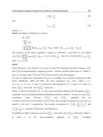
and Figure 4.5 shown different pulse shapes. We used
Gaussian doublet (2nd order Gaussian pulse) because it is the most currently adopted
pulse that meet the appropriate UWB operation with regulation explained by Benedetto
and Giancola (2004), which is usually generated by the equation.
2
2
2
2
2
() (1 4 )
t
p
w
t
pt e
pw
Here
p(t) is a Gaussian pulse (Gaussian doublet) where pulse duration or width is much
smaller than pulse repetition period, i.e.
T
p
>>P
w
, so it can produce low duty cycle
operation.
Novel Applications of the UWB Technologies
168
Fig. 4.5. Gaussian pulse shape.
The output of the modulator enters the pulse shaper filter, which acts as a low pass filter
and after convolution operation between the modulated data and Gaussian pulse. Signal
amplitude is shown for BPSK and BPAM in Figure 4.6 and transmitted pulse after shaping is
shown in Figure 4.7.
Fig. 4.6. Transmitted signal amplitude (BPSK & BPAM).
UWB Technology for WSN Applications
169
Fig. 4.7. Transmitted pulse train after shaping.
4.3 Channel
The UWB radio signal is ideally composed of a sequence of pulses that do not overlap in
time. Each pulse is confined within a specific time interval and the pulse itself has finite
duration. The received signal can be expressed as
r(t) = s(t)+n(t), 0
t
T. where n(t)
denotes a sample function of the additive white Gaussian noise (AWGN) process with
power spectral density of
N
o
/2 W/Hz. Here single user point-to-point communication
system is considered with the absence of inter symbol interference (ISI) and multi-user
interference (MUI) phenomenon. Figures 4.8 and 4.9 show the channel output of BPSK and
BPAM respectively.
Fig. 4.8. AWGN channel output (BPSK), where Eb/No=5 dB.
Fig. 4.9. AWGN channel output (BPAM), where Eb/No=5 dB.
Novel Applications of the UWB Technologies
170
The BPSK output shown in Figure 4.8 is more noise like and undetectable comparing to
BPAM output shown in Figure 4.9. The probability of error depends on the modulation
scheme and Signal to Noise Ratio (SNR). The performance of the impulse radio signal over
the AWGN channel can be realized with the BER performances as shown in Figure 4.10 and
4.11, where number of pulse per bit is one and four, while different modulation technique is
used. In the DS-UWB propagation through AWGN channel, transmitted pulses are delayed
and attenuated due to thermal noise, but multi path effect, ISI and MUI were not
considered. Here by increasing the number of pulses per bit (
N
s
), the received energy is
increased by a factor
N
s
, without increasing the average transmitted power (P
av
). To
increasing the number of pulses per bit we can achieve better SNR performance.
Fig. 4.10. BER performance BPSK, BPAM, DPSK, BPPM (
Ns=1, 4).
UWB Technology for WSN Applications
171
Fig. 4.11. BER performance BPSK, BPAM (
Ns=4).
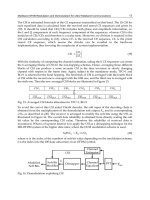
4.4 Receiver
At the receiver shown in Figure 4.3, de-modulation operation is performed with the noisy
signal. The constellation diagram is shown in Figure 4.12 and the signal after demodulation
is shown in Figure 4.13. The received signal is successfully recovered by using an energy
detection method. A sample of matlab code for detection is shown in Figure 4.14.
Fig. 4.12. Received signal constellation (BPSK, Eb/No=2, 5)
Fig. 4.13. Received signal amplitude after demodulation.
Novel Applications of the UWB Technologies
172
The decision is obtained by applying a simple majority criterion. Given the number of
pulses falling over a threshold and comparing this number with the number of pulses
falling below the same threshold, the estimated bit corresponds to the higher of these two
numbers. An error occurs if more than half of the pulses are misinterpreted. So this decision
factor achieves accurate reception and by increasing the number of pulses per bit provides
more efficiency. The length of PN code (
f_chip ) is used to correlate with the received bits
after demodulation while
f_chip/2 decision metrics provides the estimated repeat bits at
the receiver shown in Figure 4.15. Finally
N
s
/2 decision threshold facilitates to recover bits in
the de-repetition process, which are compared to the transmitted bits for error estimation.
For large number of transmitted data, no error is found as shown successfully by the
simulation results.
Fig. 4.14. Detection code.
Fig. 4.15. Output after detection (
10110010), Ns = 4.
The proposed transceiver model is efficient and ensures reliable transmission, so it is
suitable for sensor network communication system. Here, by increasing the number of
pulses per bit (
Ns), the received energy is increased by a factor Ns, without increasing the
average transmitted power but at the same time compensating the bit rate of dividing by
Ns.
Data is successfully recovered by energy detection technique (detect and avoid), which
facilitates the design simplicity at the receiver by avoiding pulse synchronization and
coherent detection. Moreover having 50% of data corruption during the propagation, the
system still recovers the bit stream accurately
(Ns/2, bit=8, Tx bit=8 4, Sum> Ns/2)
. Also
UWB Technology for WSN Applications
173
power emission and consumption are very low .(Power = 794 W and Energy per pulse =
280 nW).So it’s a noise like signal, which is difficult to detect by unwanted user and immune
to interference with other existing radio operating in the same band.
5. Summary
UWB technology is feasible for the implementation of sensor networks as it offers high
robustness to interference and provides low complexity receivers and transmitters with low
energy consumption. The IEEE 802.15.4a standard enables UWB-based sensor networks,
which offer a high degree of flexibility and includes modulation, coding, and multiple
access schemes that permit non-coherent receiver design. The specification for UWB LR-
WPAN devices incorporates a number of optional enhancements to potentially improve
performance, reduce power consumption and enhance coexistence characteristics. In
particular, DS-UWB is a suitable communication platform for wireless sensor networks
where accuracy and reliability is more important factor than bandwidth utilization. Due to
the ability of noise immunity and low probability of detection and interference rejection, DS-
UWB is a good choice for wireless sensor networks. Pictorial signal behavior shown in the
simulation process helps to realize the above-mentioned facts. The UWB information rates
as a function of transmission distance over AWGN and other channels can be considered for
further development. Moreover, in future, multiple access interference on transceiver design
can be investigated in a multi user environment. It might be interesting to explore the
coding-spreading tradeoffs, channel estimation and design of optimum transceiver
architecture.
6. References
Allen, B. (2004). Ultra wideband wireless sensor networks. IEE Seminar on Ultra Wideband
Communications Technologies and System Design, King’s College, London. Pp: 35-
36
Azim M A, et al., (2008).
Direct Sequence Ultra Wideband System Design for Wireless Sensor
Network. Proceedings of the International Conference on Computer and
Communication Engineering (ICCCE'08). Kuala Lumpur, Malaysia. Pp: 1136 to
1140
Azim M A, et al., (2008).
Development of Low-cost Sensor Interface for Wireless Sensor Network
Monitoring Application.
5th International Conference on Information Technology
and Applications (ICITA 2008), 23 - 26 June 2008, Cairns, Queensland,
AUSTRALIA.
Benedetto, M. D. and Giancola, G. (2004).
Understanding ultra wide band radio fundamentals.
Prentice Hall. Communications Engineering and Emerging Technologies Series. Pp:
121-234
Haykin, S. (2006).
Digital communications. John Wiley & Sons, Inc. New York, NY, USA. Page
445 to 471
IEEE802.15.4 specifications. (2003). Online article, Retrieved June 22, 2006, from
IEEE 802.15.4a. (2007).
IEEE Standard for PART 15.4: Wireless MAC and PHY Specifications for
Low-Rate Wireless Personal Area Networks (LR-WPANs): Amendment 1: Add
Alternate PHY. Retrieved July 2, 2007, from
Novel Applications of the UWB Technologies
174
Oppermann, I., Hamalainen, M., and Iinatti, J. (2004).
UWB theory and applications. Wiley
Press.
Reed, J. H. (2005). An introduction to Ultra wideband communication systems. Prentice
Hall.
Zeng, D. (2005).
Pulse Shaping Filter Design and Interference Analysis in UWB Communication
Systems.
Dissertation Submitted to the Department of Electrical and Computer
Engineering, Virginia Polytechnic Institute and State University.
Zhang J, et al (2009).
UWB Systems for Wireless Sensor Networks. Research article by
Mitsubishi Electric Research Laboratories. Available online at
9
Green Femtocell Based on UWB Technologies
Moshe Ran
1
and Yossef Ben Ezra
2
1
MostlyTek Ltd. 58 Keshet St., Reut
2
H.I.T - Holon Institute of Technology, Holon,
Israel
1. Introduction
The rapid evolution of mobile communications through four generations of mobile
communication, envisages the operation at 100Mb/s for mobile users and at 1Gb/s for
stationary applications in the near future. The tremendous increase of data rates must be
considered in the context of four decades of the mobile cellular technologies progress since
its first introduction by the Nippon Telephone and Telegraph Company (NTT) in the late
70's Rappaport (2002). On the other hand, fixed wireless communications are already
available to provide over 300 Mbps raw data rates through wireless local area networks
(LAN) protocols as 802.11n, and over 1Gbps through Ultra Wideband (UWB) in wireless
personal area networks (PAN), see (ECMA-368), (ECMA-387).
With the introduction of the femtocell concept Zhang (2010), new opportunities have been
opened for approaching the 4G mobile vision through fixed mobile convergence (FMC).
Femtocell Access Point (FAP), are low power access points that connect mobile terminal to
the mobile core network using wired broadband or fixed broadband wireless technologies.
The FAP provides viable opportunities for mobile operators, to meet the indoor coverage
challenges for most demanding applications at low cost.
We propose a novel concept of 4G femtocell, denoted a "Green Femtocell", and high level
network architecture to support the new paradigm of FMC, in which convergence of 4G
cellular with short-range wireless and wired are realized. The proposed approach paves
the way of green framework in which increase by x100 in energy efficiency and x100
reduction of human exposure to wireless radiation become feasible.
Our approach relies on radio-over-fiber and all-optical solutions that can already be
considered "green" in offering reduced energy consumption to alternative wireless access
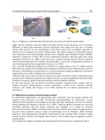
solutions, see CELTIC Purple Book (2011). The new concept is based on the following novel
technical and business entities (Fig. 1):
We introduce a green remote Home Access Node (HAN) that relays range of radio
protocols, including UWB, WLAN, LTE-A, and IEEE 802.16m as radio signals over
hybrid wireless-fiber media from 1.8 GHz to 10.6 GHz; with strict limitation of radiated
power. Wireless radiation for indoor environments is reduced by 2-3 order of
magnitudes, while potentially support target 1Gbps end-user data rates, by using
dual-mode cellular-UWB for most common indoor applications. Indoor HAN should
support mobile users at distances ranging from 0.3m to 30m over-the-air. For outdoor
Novel Applications of the UWB Technologies
176
and longer range indoor topologies, we enable protocol-transparent architectures
capable of relaying range of radio protocols from 30 to 300 m.
Processing for multiple HANs is centralized with optical Multi-cell Base Station (O-
McBS) capable of performing parallel multiple input multiple output (MIMO)
processing of radio-over-fiber (ROF) links over 100's of GRANs. Unlike the McBS
approaches suggested in Foshini (2006) and Gambini (2010), our O-McBS approach
involved with optical MIMO over multi mode fiber (MMF). The multicell processing
performed at McBS enables clear benefits of centralized approach to interference
management over the hybrid wireless-fiber medium and efficient radio resource
managements (RRM). We note that MIMO over MMF is a very recent enabling
technology that has been shown to attain 400Gb/s signalling rate over several hundreds
of meters of MMF at 10
-10
BER Greenberg (2007). A promising solution for radio
signalling and multiple access over hybrid wireless-MMF is based on orthogonal
frequency-division multiple access (OFDMA). However, most of the works have
addressed only the indoor wireless channels Perez (2009).
O-McBS are connected through optical femto gate way (O-FemtoGW) to core network
through Tb/s optical links. O-FemtoGW multiplex data from 10's of O-McBS, and forms
through all-optical real-time processing an optical OFDM (O-OFDM) signal carrying
100Gb/s. Recently, works on all optical FFT schemes to implement efficiently O-OFDM
to enable 1 Tb/s have been published by Hillerkuss (2010). Recent survey on O-OFDM
with MIMO can be found in Shieh (2010), and general aspects of O-OFDM in
Armstrong (2009) and Gidding (2009).
R
F
E/ O
O/E
PHY
PHY
HAN
#1
PHY
O-
McBS
HAN
#n
Mult i Mode F
iber
(
MMF
)
Femto
-
N
SP
AAA
Network mng
.
MM
F
MM
F
1
Tb
s/s
NSP: Network service provider MMF: Multimode Fiber
O-McBS: optical multicell BS RRM: radio resource management
MAC: Medium access control E/O: Electrical/Optical converter
O/E: Optical/Electrical converter
Fig. 1. Green Femtocell Access Network (high-level architecture).
Green Femtocell Based on UWB Technologies
177
The proposed architecture leverages and extends the concepts and technologies of UWB
radio over optical fiber (UROOF) Ran (2010a, b), Ben-Ezra (2010), and further investigated in
the context of future mobile technologies in Ran (2009) and Altman (2010). Our technical
approach is directed to solve the crucial problem of interference management in local area
environments in femtocells deployment. The femto-to-macro co-channel interference is
solved by allocating unlicensed frequencies for indoor (e.g., UWB, WLAN). The femto-to-
femto interference is addressed through centralized approach within the O-McBS.
In this chapter we focus on the local area coverage through HAN and elaborate possible
indoor and outdoor architectures that can support 4G femto mobile vision in the near
future. The chapter is organized into the following sections. In Section 2, we review state of
the art of femtocell technology. In section 3, we review the very-low radiation distributed
antenna system (VLR-DAS) concept. We elaborate indoor architectures and performances of
green femtocells, and further extend the discussion to outdoor architectures in section 4. In
section 5, we provide interference analysis for single cell and multiple cell scenarios and
discuss mitigation techniques to enable co-existence with other systems. Theoretical and
experimental investigation is provided in Section 6. Conclusions are presented in Section 7.
2. Femtocells technologies
The use of densely deployed many low-power, low cost and high performance base stations,
e.g., FAPs, seems a promising approach to cope with the ever-growing indoor coverage
demand. Since 70% of voice and more than 90% of data services occur indoors Roche (2010),
it becomes promising to deploy in-house FAP, which connects standard mobile devices to a
mobile operator's through existing broadband Internet connection. According to a recent
market prediction, Jarich (2010), leading femtocells vendors expect 2013 to be the year in
which LTE and possibly WiMax femtocells will be commercially deployed. Femtocells are
potentially industry-changing disruptive shift in technology for radio access in cellular
networks. Femtocells should provide small scale functions of BS, and also certain functions
of the customer premises equipment (CPE). Therefore, to gain benefits for network
operators and consumer, the interaction between femto and macro radio layers should be
carefully managed.
2.1 State of the art of femtocells
FAP's can be classified into two categories: home FAP, also called home base station (HBS),
or enterprise FAP. HBS typically supports 2- 8 simultaneous users, where enterprise FAP
can support 4 – 16 users, and can easily configured in cascade architecture to support 32- or
64-simultaneous users. FAP can further be classified according their underlined cellular
technologies: GSM -, UMTS -, LTE-, WiMax -, FAP etc.
Femtocells can be configured in three ways to restrict and control their usage by certain
users. In open access (or public access) all users, including outdoor users, or neighbouring
femtocells are able to make use of nearby femtocells. In closed access (or private access)
only a list of registered users are allowed to access a femtocell. In Hybrid access
nonsubscribers use only limited amount of the femtocell resources, as e.g., emergency call
services.
Open access benefits outdoor users, who are making use of nearby indoor femtocells and
thus clearly improve the overall capacity of the network. From interference point of view,
Novel Applications of the UWB Technologies
178
open access is superior to closed access, since it allows customers to connect to nearest
access point. Thus it enables reducing the overall use of system resources (power-frequency-
time). Possible drawback to this approach is the increase number of handoffs. Additionally,
the femtocell customer pays by himself for the FAP and the broadband Internet connection,
and is likely to reject the sharing of his own resources with users passing by his
neighbourhood.
Some key technical challenges to large scale femtocell deployment are the following Yongho
(2009):
Interference to/from other femtocells and macrocell BS. Massive deployment will pose
serious issues on the radio interference management with the surrounding cells (both
femtocelss and macrocells). Since femtocells are planned to be installed in an ad-hoc
manner by end-users and in large numbers, it will be challenging to do centralized and
coordinated radio planning as in legacy macrocell system.
Seamless Handover between a femtocell and macrocell or other femtocells. The
conventional broadcast mechanism to advertise neighbour BS information may not be
viable and scalable to include information about femtocells due to the excessive
overhead needed. In the absence of this information, the macrocell-to-femtocell
handover becomes challenging. In particular, handouts (femto to macro) and handin
(macro to femto) efficient algorithms are required.
Lack of standard solutions for scalability, redundancy and traffic partioning. For the
femtocells to be widely used, it is essential that femto BSs interface with the rest of the
network, both control and management planes, be fully standardised. No current
guarantee that the fixed broadband connection will prioritize the traffic originating
from the FAPs for a service without call blocking or dropping. It is highly desired that
implementation of standard solutions be verified for multivendor interoperability.
Synchronization and location. Inter-cell synchronization and femtocell location are
critical for proper operation of femtocells, but GPS cannot be used in many indoor
cases. Therefore, solutions for timing synchronization and location are needed.
Many aspects of current state of the art of femtocells technologies were published within the
special issues of IEEE communications magazine (September 2009 and January 2010).
Several research projects within the seventh EU framework program for research and
technological development (FP7), and industry-driven research initiative CELTIC-Plus
framework (www.celtic-initiative.org ) are addressing some key aspects of future femtocells
technologies.
HOMESNET project, supported in part by CELTIC (CP6-009), is focused on three key
challenges in HBS: dense deployment of self-organizing networks (SON), self-optimization
and low radio emissions, Altman (2010). To achieve very low radio emissions in the house
or constrained environment like hospitals, an architectural network option for HBS based on
radio-over-fiber approach is investigated. The HOMESNET vision can certainly provide a
good starting point for the new paradigm of Green Femtocell concept described in this
chapter.
FREEDOM project (Femtocell-based Network Enhancement by Interference Management
and Coordination, see www.ict-freedom.eu) aims at improving the efficiency of networks
with massive femtocell deployment. The focus is on addressing the key question: How
much the whole system efficiency can be improved by exploiting the available quality of the
IP-based backhaul link?
Green Femtocell Based on UWB Technologies
179
The solutions addressed in FREEDOM include the two main flavours of the 4G femtocell
paradigm, namely IEEE 802.16m and LTE-Advanced. In both cases the core concepts
investigated are: Interference management and cooperation; dense femtocell-specific RRM;
scalability and effectiveness and femtocell-based network planning.
BeFEMTO (Broadband Evolved FEMTO Networks, see www.ict-befemto.eu) is a recent
integrated FP-7 project aiming to develop femtocell technologies based on LTE-A. The
project is targeting ambitious objectives such as:
Minimum system spectral efficiency of 8 b/s/Hz/cell.
A maximum averaged transmit power of less than 10mW for indoor femto nodes.
Seamless convergence between fixed broadband and mobile cellular systems.
Rocket (Reconfigurable OFDMA-based Cooperative Networks Enabled by Agile Spectrum
Use, see www.ict-rocket.eu) is another FP7 project aimed at providing solutions for LTE-A
and 802.16m to reach data rates 100Mbps and peak throughput higher than 1Gbps. The
technical approach is based on advanced opportunistic spectrum usage, multi-user
cooperative transmissions and ultra-efficient MAC design.
2.2 Standardization of Femtocells
Since a femtocell is a small scale cellular BS, it transmits over RF bands using licensed
spectrum granted by the appropriate government authority. This requires that mobile operator
be responsible for the control of radio transmission in a strict way, and follows regulations and
standards. Standardization is certainly important for femtocells market to reach massive
deployment. There are several standard development organizations (SDOs) and non-SDO
forums that play an important role in the standardization of femto technology.
SDOs:
3GPP (www.3GPP.org) was created in 1998. The 3rd Generation Partnership Project (3GPP)
unites 6 telecommunications standards bodies from Asia, Europe and North America. Over
350 companies participate in 3GPP through their membership of one of the 6 partners. The
scope of 3GPP is to produce Specifications for a Mobile System based on evolved GSM core
networks and the radio access technologies that they support. The femtocell concept applies
as modifications for 2G/3G/4G mobile cellular generations described below in TABLE 1.
Recent success with the creation of LTE and Systems Architecture Evolution (SAE)
Specifications has made 3GPP the focal point for Mobile Broadband systems and a genuine
contender as point of convergence for future Specifications for mobile networks. The
standardization is defined in series of Technical Specification (TS) and Technical Reports
(TR). The work is done through several working groups RAN2–RAN4 and SA1-SA5.
3GPP Radio Interfaces
2G radio: GSM, GPRS, EDGE
3G radio: WCDMA, SSPA, HSPA,
LTE
4G radio: LTE Advanced
Rel.99
Rel.4 – 7
Rel. 8 /9
Rel. 10
3GPP Core Network
2G/3G : GSM core network
3G/4G: Evolved packet Core (EPC)
Rel. 8
3GPP Service layer
GSM, IMS, Multimedia Telephony
(MMTEL),
Rel. 9
Table 1. 3GPP key releases and areas in which Femtocell concepts apply
Novel Applications of the UWB Technologies
180
Recent reference model for stage 2 UTRAN architecture for 3G Home NodeB (HNB) was
finalized in 3GPP RAN3 within TS 25.467. The basic elements of Iu-h interface are given in
Fig. 2. The HNB connects to the mobile core network through HNB-GW, which acts as a
concentrator to aggregate large number of HNB's. The Iu-h interface goes through a security
gateway (SeGW) to HNB-GW. The HNB Management System (HMS) is based on TR-069
family of standards and provides authentication of HNBs and access from HNB to HNB-
GW.
Fig. 2. Iu-h reference point in 3GPP for 3G Home NodeB.
Evolution to IMS/HSPA+/LTE is addressed in 3GPP TR R3.020. In January 2009, the
3GPP published overall architecture of LTE HeNB architecture within TS 36.300-870.
The 4G aspects of 3GPP are studied within the 3GPP approach to address the ITU's IMT-
advanced system. Key 4G based on LTE-Advanced features, as defined within 3GPP Rel.10
and are summarized below.
Channel BW. Support for wider bandwidth (up to 100MHz).
Downlink transmission scheme will support data rates of 100Mb/s with high mobility
and 1Gb/s with low mobility. It will be improvement to LTE along the evolution path
by using 8x8 MIMO.
Uplink transmission scheme supports data rates up to 500Mb/s.
Relay functionality. Improvement to cell edge coverage and more efficient coverage in
rural areas.
Coordinated multiple point transmission and reception (CoMP) in both downlink and
uplink
LIPA (local IP Access) & eHNB (enhanced HNB) to allow traffic off-load
3GPP2 (www.3GPP2.org) was created in 1999 as a partnership among SDOs from US, Korea
and Japan and more recently from China to facilitate the CDMA based radio technologies
for mobile cellular evolving from the IS-95 CDMA family of standards. The 3GPP2
architecture for femtocells is heading toward all-IP architecture for voice services based on
Session Initiation Management Protocol (SIP), (see RFC3261), and IP multimedia sub-
system (IMS) (see TS23.238)
BBF (Broadband Forum, previously DSL Forum, see www.brodbandforum.org) The TR-069
was originally created to manage DSL gateway device, and has been grown over the years
for supporting new devices including femtocells. These modifications were published as
amendments in (BBF TR-069), (BBF TR-098) and (BBF TR-106). In 2009 the forum published
its data model for femtocells (BBF TR-196), supporting interoperability between FAP and
network equipment.
HNB
SeGW
HNB-
GW
HMS
Uu
lu
lu-h
Green Femtocell Based on UWB Technologies
181
Non- SDO bodies and forums relevant to the femtocells paradigm:
The Femto Forum (www.femtoforum.org) has around 100 members from all parts of
femtocell industry: major operators, major infrastructure vendors, vendors of components
and subsystems. Femto Forum works with SDO and regulators worldwide to provide an
aggregated view of femtocells market. The forum is focused on building and maintaining an
eco-system that delivers the most commercial and technically efficient solutions based on
femtocells. It has now four working groups (WGs): marketing & promotion, radio &
physical layer, network & interoperability and regulatory. Recently four special interest
groups (SIGs) were founded: LTE, WiMAX, Interoperability and Services.
Femto Forum started discussions on femto architectures with 15 variations early 2008, and
soon converged into only one based on Iu-h that has led to the proposal to 3GPP.
WiMAX forum (www.wimaxforum.org) is an industry-led organization that certifies and
promotes the compatibility and interoperability of broadband wireless products based upon
IEEE Standard 802.16. The forum has hundreds of members, comprising the majority of
operators, component vendors and equipment vendors in the communications ecosystem.
The WiMAX Forum’s primary goal is to accelerate the adoption, deployment and expansion
of WiMAX technologies across the globe while facilitating roaming agreements, sharing best
practices within our membership and certifying products. WiMAX products are
interoperable and support broadband fixed, nomadic, portable and mobile services. WiMAX
has two phases for femtocell evolution:
Phase 1 is "femto aware" version based on IEEE802.16-Rev2 network release 1.6 and system
profile release 1.0/1.5 with basically no change in the air interface standard to enable basic
femtocell deployment. This version was completed late 2010.
Phase 2 "femto enhanced" version is based on network release 2.0; system profile release 2.0
and the air interface defined in 802.16m. This version is expected to be completed by 2012
with target deployments in 2012-2013.
NGMN (next Generation Mobile Networks ) Alliance was founded
by leading international mobile network operators in 2006, and joined recently (May 2011)
the 3GPP as a market representation member. Its goal is to ensure that the standards for next
generation network infrastructure, service platforms and devices will meet the requirements
of operators and, ultimately, will satisfy end user demand and expectations.
GreenTouch (www.greentouch.org) is a recently established consortium dedicated to
fundamentally transforming communications and data networks, including the Internet,
and significantly reducing the carbon footprint of ICT devices, platforms and networks. By
2015, its goal is to deliver the architecture, specifications and roadmap — and demonstrate
key components — needed to increase network energy efficiency by a factor of 1000 from
current levels.
3. Green femtocell and Very-Low Radiation Distributed Antenna System
(VLR-DAS)
The basic idea of distributed antenna system (DAS) is replacing an antenna radiating at high
power with N small antennas using low-power. Passive DAS use only passive elements as
splitters, taps, terminators, circulators, filters and coaxial cables to split the RF signals into N
antennas. Active DAS use different active elements (amplifiers, convertors E/O and O/E).
Radio-over-fiber (ROF) DAS are most common active DAS techniques currently used.
Novel Applications of the UWB Technologies
182
3.1 Passive DAS
The basic features of Passive DAS are well known Saleh (1987). The benefits of passive DAS
using Omni antennas are discussed in Chow (1994). In particularly, the following useful
features are evident:
Maximizing coverage area. For a given radiated power, wireless channel with path loss
exponent
, N antennas system will have an increased coverage area over a single
antenna system by factor
2
1
N
.
Minimizing the radiated power. For a given coverage area, an N antenna system will
have a reduction in minimum required radiated power in downlink channel by the
factor of
1
2
N
compared to single antenna system. Furthermore, the maximum
radiated power in the uplink channel will be reduced by the factor
2
N
.
Minimizing maximum path loss. For a given coverage area, an N antenna system will
have reduced maximum path loss by factor of
2
N
.
Minimizing far-field interference. For a given coverage area, an N antenna system
will have reduced far field interference by factor of
2
N
Thus for example, for N=8 and
=5 and given coverage area, radiated power reduction of
22.6 (13.5dB) will be achieved for the downlink and 181 (22.6dB) in the uplink compared to a
single antenna system. With such deployment, radiation from MS is reduced by 22.6dB and
thus the C/I is improved by the same factor.
3.2 Active DAS
A typical active DAS uses master unit, which is the intelligent part of the active DAS, to
distribute the RF signals from the BS antenna to multiple expansion units over an optical
fiber of lengths up to 6km. Each expansion unit is connected to multiple remote radio units
(RRUs) with thin coax, CAT5 or fiber of lengths up to 400m. Unlike passive DAS, active
DAS has the ability to automatically compensate for the losses in the system by using
internal calibrating signals and amplifiers. Active DAS is the preferred solution for large
building and can provide monitoring and alarms in the event of malfunction.
DAS can be combined with MIMO communications concepts by treating the RRU's as a
distributed antenna array, see Heath (2010). The multi-user MIMO DAS system model is
given in Fig. 3
The model considers R RRUs in each cell, each BS and RRU are equipped with N
t
antennas
and mobile user with N
r
=1 receive antennas. Some aspects of MIMO DAS using beam-
forming have been addressed in Li (2009). However, the overall benefits of multiuser MIMO
DAS have not been established yet in DAS deployments Heath (2010).
Recently, there has been much research interest on the cooperative (or collocated) antenna
system (CAS). It is shown You (2011) that theoretically CAS can alleviate major problems of
the cellular systems as intercell interference (ICI) and cell edge effect problem. The
performance of CAS depends very much on the degree of cooperation. In one extreme, the
CAS consists of several distributed antennas which are connected to a central processing
unit. This type of CAS is the DAS case, which has the best performance. In the other
Green Femtocell Based on UWB Technologies
183
extreme, the BTS only exchange limited information, normally in order to boost the
performance of the UEs at the edge of the cell. This case is also known as the Coordinated
Multiple Point Transmission and Reception (CoMP) system. In this case, the transmission of
the data is coordinated in time, frequency or space so as to minimize the inter-cell
interferences and propagation loss effects. The CoMP concept for both uplink and downlink
is central concept in LTE-A systems defined through 3GPP rel. 10 and future versions.
Fig. 3. The MIMO DAS multi-user system, Health (2010).
3.3 Very Low Radiation DAS (VLR-DAS) approach
Lowering energy consumption of future wireless radio systems along with great reduction
of the wireless radiation indoor are important keys to next generation of mobile radio access
systems. As transmitted data volume increases by factor 10 every 5 years, new technologies
and solutions are becoming essential to support this trend while meeting the energy
consumption along with the wireless radiation. The VLR-DAS concept, Ran (2010c), targets
the distribution of various radio-protocols including 3G, LTE, IMT-Advanced and WiMax at
a very-low radiation based on radio-over-X (optical fiber, Coax, Cat-5, power-line etc.). The
focus is on scalable hybrid wired-wireless topologies to achieve a remarkable reduction of
the emitted power to minimum level (order of 1mW and less) needed for coverage of small
cells.
VLR-DAS approach in the context of 3G femtocell paradigm is described in Fig. 4, Ran
(2010c). The new functional device, called Home Access Node (HAN) is a special version of
RRU with strict limitation of radiated power to below 1mW over the air. HAN also used to
adapt the RF signal to the wired media with minimum distortion, and perform initial
identification and filtering of target radio signal.
Mobile
user
RRU
BS
Novel Applications of the UWB Technologies
184
HNB
HNB GWSeGW
HMS
Iuh Iu
Core
Network
HAN
Fig. 4. 3G femtocell logical architecture Deployment configuration/Options with HAN
function
Some general requirements for the successful operation of HAN with 3G femtocell are the
following.
The introduction of the HAN as an intermediate unit between HNB and the UE should
not affect the 3G protocol stack between the HBS and the core network.
Coexistence of the relayed radio signals with other radio signals (adjacent HBSs, macro
BS, WLAN etc.) is required both for wired and for the wireless indoor infrastructure.
The transmission of the various radio signals from the HBS through the HAN and the
wired-wireless infrastructure to the UE should introduce minimum delay and
negligible distortion to the performance of the communication link between HBS and
UE.
VLR-DAS basic scenarios
Case 1: Residential in-house distribution network. For home users the VLR-DAS concept
implies using the distribution of target wireless signals inside small number of rooms (say
less than 8) based on existing and future home infrastructure. The radio signals are relayed
transparently from one HBS to several rooms as "radio-over-wired" signals (with possibly
frequency translate over wired home infrastructure). The wired part is serving as a "range
extension" unit over 10's of meters to a set of HANs. Each HAN transmits at minimum
power (less than 1mW) to cover a single room of less than 10m.
This case, shown in Fig. 5, is based on the simplified serial concatenation of several HAN's
connected through a multimode fiber (MMF). The use of a separate fiber for the uplink and
downlink conversion aimed to simplify and reduce the cost of the HAN implementation. In
this example, HAN#1 serves as the Master Unit (MU) that communicates with the HBS (or
external macro BS either directly, or through a repeater) over the air to simplify the
installation of the home network. The other HAN's transmit the radio signals over the air to
the target UE.
Case 2: Enterprise "Green Hospital". The Green Hospital represents a corporate use case of
citizen-to-authority and authority-to-citizen (C2A-A2C) where the exchange of large amount
of medical data over 100s of femtocells is considered. Here the range extension over the
wired media is 100-3000m, and hundreds of users are supported through highly dense
multi-femtocells architecture.
In hospitals the need for wireless is growing exponentially because all kinds of “vital signs”
functions are monitored continuously. In hospital networks, there is an inherent
inconsistency between the wish for mobility of the monitored patients and the interference
of the radio signals with the sensitive diagnostic equipment. At present, some 8-10 functions
per patient are wirelessly recorded. The number of monitored functions will grow rapidly in
Green Femtocell Based on UWB Technologies
185
the coming years. In many cases the monitoring of patient functions is done wireless
because of the need for improved “quality of life” for the patients. In essence, the use of
“wireless” in a hospital is conflicting with the safety and security demands for the sensitive
diagnostic and patient treatment equipment. Green Femtocell would be a great benefit by
enabling unique capabilities to medical centres and health management offices (HMO).
Femtocell
HAN 1
HAN 2
F
d1
F
u1
F
d1,
F
dN
F
u1
F
d1
F
u1,
F
uN
6 -10 m
6 -10 m
10 – 100 m
HAN 3 HAN 4
10 – 100 m 10 – 100 m
Fig. 5. Typical residential configuration of VLR-DAS over 4 rooms
Green hospital scenario for radiological department: The relevant patient data including
previous examination images is transmitted within 1-2 seconds to the HAN sensor located
near the desk. The data includes also medical information such as allergy to contrast media
or renal failure, which will pop-up automatically on the screens of the staff in the
department. The images are transferred from the HAN on the front desk immediately to the
Picture Archiving and Communication System (PACS) via the wired optical fiber backbone.
The PACS consists of Host Communication Controllers (HCCs) and the central Hospital
Information System (HIS). HIS data would appear automatically on the computer screen on
the desk. Then, the secretary has just to show the data to a visitor in order to get his
confirmation that the data are correct.
Fig. 6. Green Hospital scenario for radiological department.
HAN
Novel Applications of the UWB Technologies
186
Derivatives of this scenario for fast exchange of medical records such as part/all the medical
history of a patient may include: summary and reports of medical visits in different clinics,
all laboratory results as blood tests, urine, previous ECG records, etc. obtained during the
patient's life. It may include large files of diagnostic imaging procedures, pathology and
histology results (including digitalized images), summary or lists of previous and currently
active diseases, side effects and hypersensitivity reactions to drugs and contrast media,
allergies, family history, a list of drugs taken by the patient, etc.
3.4 Experimental results of VLR-DAS for 3G UMTS
Some results of UMTS Green Femtocells were published in Ran (2010c). Fig. 7 shows the
experimental setup for the testing of the VLR-DAS concept in Case 1. The system comprised
a femto BS (Agilent E4432B) transmitting "green" W-CDMA FDD signals of -20dBm at band
I (UL: 1920 -1980 MHz and DL: 2110 -2170MHz). We used the Test Model 1 containing 64
DPCH signal. The optical sub-system contained 10Gbps 850nm Vertical-Cavity Surface-
Emitting Laser (VCSEL) for the direct E/O conversion of the W-CDMA signal into radio-
over-fiber (ROF) signal. The ROF UMTS signal propagated through a standard MMF (type
OM3) of the length of 30m, and was detected by a PIN diode. Then, the detected signal was
onward transmitted through the tested channel to the W-CDMA receiver. The purpose of
this experiment was the study of the wired channel performance. The measured gain of the
wired channel is about 3dB. The performance of the wired channel strongly depends on the
RF signal power level at the VCSEL input due the VCSEL strong nonlinearity.
Fig. 7. Experimental set-up for UMTS in VLR-DAS scenario.
As shown in Fig. 8, the optimal value for the input RF power is about -30dBm. The input
power values above -25dBm lead to distortions expressed by higher order intermodulations
and link gain degradation which affect the error vector magnitude (EVM). EVM and link
gain vs. input signal power were recorded for the various scenarios. The EVM degradation,
denoted ∆EVM, is obtained by comparing the EVM for the "best case" where BS is directly
connected to the HAN, i.e., no optical or wireless segment, and the wired case where HAN
is directly connected to the BS, and through the optical segment to the UE.
Green Femtocell Based on UWB Technologies
187
Fig. 8. EVM and link gain for the wired case. The HAN is connected to the BS through a
wired connection and to the user through VLR-DAS optical segment. The link shows
negligible performance degradation over wide range of input power.
Fig. 9 shows the gain and ∆EVM for a combined wireless-wired channel and different
lengths of wireless segments. The measured gain of the combined channel is about 15dB.
Although the combined wireless-wired channel causes the degradation of EVM in the range
of 8% -15%, still the satisfactory performance of EVM values below 11% is observed.
Fig. 9. EVM and link gain for the wireless-wired case. The HAN is wirelessly connected to
BS and connected to the user through VLR-DAS optical segment.
Novel Applications of the UWB Technologies
188
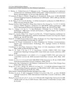
4. 4G green femtocell: Indoor architectures based on MB-OFDM UROOF
technologies
The UWB radio over optical fiber (UROOF) was investigated recently in series of works, see
(UROOF), Ran (2010a, b, c), Ben-Ezra (2010), Kraemer (2009) and Ran (2009). In this section
we propose a framework, based on UROOF technologies, to elaborate indoor architectures
for implementing the 4G green femtocell paradigm (see Fig. 1). We start with the proposed
wireless air interface based on MB-OFDM UWB. We then provide some experimental data
on transmitting multi-gigabits data over hybrid fiber-wireless channels and review MB-
OFDM with MIMO as a promising approach for the compound indoor wireless-MMF
channel.
4.1 MB-OFDM UWB over wireless indoor channel
MB-OFDM has been proposed for the draft standard 802.15.3a (withdrawn on January 2006)
and by the WiMedia Alliance in ECMA-368. MB-OFDM UWB is a combination of extremely
broadband OFDM signal and frequency hopping, in which 528 MHz channels are selected
over the entire 7.5GHz bandwidth between 3.1 to 10.6 GHz. Time frequency codes (TFCs) of
length 6 are used to select a sequence of "logical channels" from a band group. Unique
logical channels are defined by using up to seven different TFC codes for each band group.
TFCs for band group 1, according to (ECMA-368) are given for example in Table 2.
TFC Number BAND_ID for Band Group 1
1 1 2 3 1 2 3
2 1 3 2 1 3 2
3 1 1 2 2 3 3
4 1 1 3 3 2 2
5 1 1 1 1 1 1
6 2 2 2 2 2 2
7 3 3 3 3 3 3
Table 2. Time Frequency codes patterns for band group 1
There are 5 Band Groups (see Fig. 10):
Band group #1 is mandatory, remaining (#2 – #5) are optional.
Only two Time-Frequency coded Logical Channels for Band group #5.
Band group #2 can be avoided when interference from U-NII bands is present.
f
3432
MHz
3960
MHz
4488
MHz
5016
MHz
5544
MHz
6072
MHz
6600
MHz
7128
MHz
7656
MHz
8184
MHz
8712
MHz
9240
MHz
9768
MHz
Band
#1
Band
#2
Band
#3
Band
#4
Band
#5
Band
#6
Band
#7
Band
#8
Band
#9
Band
#10
Band
#11
Band
#12
Band
#13
10296
MHz
Band
#14
Band Group #1 Band Group #2 Band Group #3 Band Group #4 Band Group #5
Fig. 10. Band plan for 3.1-10.6 GHz MB-OFDM with centre band frequencies shown.
Green Femtocell Based on UWB Technologies
189
The MB-OFDM signal can be expressed by
1
,(mod6)
0
() Re ( )exp 2
N
MB OFDM OFDM k OFDM k
k
xt xtkT jft
Where,
,
()
OFDM k
xt is kth the OFDM symbol of duration
OFDM
T , N is the number of
transmitted OFDM symbols and
k
f
is the carrier frequency over which the symbol is
transmitted. The designed value for
OFDM
T is 312.5ns, where information length is 242.4ns,
9.5ns kept for guard time, and 60.6ns are length of the cyclic prefix, providing guard against
multipath of length up to 60.6ns.
UWB wireless channel models were developed within IEEE 802.15.3a group during 2002 for
the range 0-10m. The model defines four radio environments, based on simplified Saleh-
Valenzuela (S-V) channel model, Saleh (1987a):
CM1: near line-of-sight (LOS) with distance of 0-4 m between Tx and Rx.
CM2, 3: non-LOS for a distance 0-4m, 4- 10 m, respectively.
CM4: heavy multipath environment.
Realistic simulations over CM1-CM4 were carried out in which: losses due to front-end
filtering, clipping at the DAC, DAC precision, ADC degradation, multi-path degradation,
channel estimation, carrier tracking, packet acquisition, overlap and add of 32 samples
(equivalent to 60.6 ns of multi-path protection), etc. were considered. The distance at which
the MB-OFDM system can achieve a PER of 8% for a 90% link success probability is
tabulated in Table 3 below:
Range AWGN CM1 CM2 CM3 CM4
110 Mbps 20.5 m 11.4 m 10.7 m 11.5 m 10.9 m
200 Mbps 14.1 m 6.9 m 6.3 m 6.8 m 4.7 m
480 Mbps 7.8 m 2.9 m 2.6 m N/A N/A
Table 3. Simulation results of MB-OFDM over practical indoor channel models
An improved version to this model was published within IEEE 802.15.4a, based on more
detailed field measurements. The model allows a larger number of environments; treats the
number of clusters of multipath components in the S-V as a random variable and allows
frequency dependence of the path loss, according to the following formula.
/2
2
/2
() (') '
ff
ff
PL
f
EH
f
d
f
E is taken over large enough area to allow averaging out the small scale fading as well as
shadowing.
f
is chosen small enough so that the dielectric constant, diffraction
coefficients are constant within that bandwidth. An updated survey on UWB propagation
channels is given in Chapter 3 of Kraemer (2009).
Novel Applications of the UWB Technologies
190
4.2 MB-OFDM UWB radio over mixed wireless-MMF
Channel impairments of MMF fibers are overviewed in Shieh (2010). When addressing the
mixed wireless-MMF with MB-OFDM UWB technology, both frequency selective fading
due to time delay spread over indoor channel, and multimode dispersion in MMF links
should be considered. In particular, the cyclic prefix design for OFDM symbol should be
longer than maximum delay due multipath wireless propagation and multimode dispersion
spread in MMF.
A simplified model for UROOF "optical relay system" is given in Fig. 11, Ran (2010a),
consisting of MMF, directly modulated VCSEL and a photodetector (PD) PIN diode.
It is shown based on series of experiments with UROOF platform (UROOF) that range
extension by two orders of magnitude can be achieved for all MB-OFDM UWB RF signals.
A highly efficient method of RF and optical signal mixing to achieve optical OFDM
transmission of MB-OFDM beyond 40Gbp/s was presented recently by Ben-Ezra (2010). The
first concept is based on parallel–RF/serial optics architecture shown in Fig. 12. Basically,
this architecture takes 128 conventional WiMedia/ECMA baseband channels of 528MHz
and uses all-optical mixing to multiplex them over SMF. One of the key advantages of such
approach is the ability to provide hybrid fiber-wireless solution, where the wireless segment
at the available ultra-wideband (UWB) transmission is fully compliant with UWB
regulations.
Fig. 11. UROOF channel consisting of an optical link (VCSEL-MMF-PD) and a wireless
channel
Green Femtocell Based on UWB Technologies
191
Fig. 12. 61.44 Gb/s based on parallel RF/Serial optics with N=128 channels
Another architecture based on parallel-RF/parallel-optics based on 12 low cost VCSELs
array that transmits over bus of 12 MMF fibers to array of 12 photo detectors s is analysed in
Ben-Ezra (2010).
4.3 MB OFDM UWB with MIMO over the wireless channel
Dense deployment of low-power femto BSs offers significantly higher capacity per area than
legacy macrocells due to more efficient spatial re-used and smaller cell size. MIMO
techniques permit to exploit the rich scattering of short range indoor wireless channel to
increase the spectral efficiency linearly. The UWB-MIMO studies can be classified into four
categories Kaiser (2009):
MIMO channel modelling and measurement. Spatial characterization of UWB MIMO
channel is given in Malik (2008).
Channel capacity. It was shown in Zheng (2006) and Martini (2007) that the system
capacity is limited by
N
T
, the number of Tx antennas, N
R
number of receiving antennas,
and
, the number of spatial degrees of freedom of scattered field. A fundamental
result by Telatar (2000) showed that for achieving channel capacity at low SNR input
signals must be spiky in time or frequency.
Space-Time Coding (STC) for MB OFDM MIMO is presented in Siriwongpairat
(2006). By applying space-time-frequency coding across K OFDM symbols maximum
achievable diversity order of
KLN N
TR
can be achieved, where L is the number of
resolvable paths.