Nuclear Power Deployment Operation and Sustainability Part 14 pot
Bạn đang xem bản rút gọn của tài liệu. Xem và tải ngay bản đầy đủ của tài liệu tại đây (1.19 MB, 35 trang )
Nuclear Power – Deployment, Operation and Sustainability
444
Whatley M.E., McNeese L.E., Carter W.L., Ferris L.M. & Nicholson E.L., 1970, Engineering
development of the MSBR fuel recycle”, Nuclear Applications and Technology, vol. 8,
170-178.
Zousyokuro Yoyuuenn (1981) Rev. Ed., Atom. Ene. Soc. Japan (in Japanese).
Part 6
Advances in Energy Conversion
18
Water Splitting Technologies for Hydrogen
Cogeneration from Nuclear Energy
Zhaolin Wang and Greg F. Naterer
Clean Energy Research Laboratory, Faculty of Engineering and Applied Science,
University of Ontario Institute of Technology (UOIT), Ontario,
Canada
1. Introduction
Currently, nuclear energy is mainly utilized for the generation of electricity that is distributed
to end users via power transmission networks. However, there are also other distribution
forms. For example, hydrogen produced from nuclear energy is a promising future energy
carrier that can be delivered to end users for purposes of heating homes, fuel supply for
hydrogen vehicles and other residential applications, while simultaneously lowering the
greenhouse gas emissions of otherwise using fossil fuels [Forsberg, 2002, 2007]. Current
industrial demand for hydrogen exists in the upgrading of heavy oils such as oil sands,
refineries, fertilizers, automotive fuels, and manufacturing applications among others.
Hydrogen production is currently a large, rapidly growing and profitable industry. The
worldwide hydrogen market is currently estimated at about $300 billion per year, growing at
about 10% per year, growing to 40% per year by 2020 and expected to reach several trillions of
dollars per year by 2020 [Naterer et al., 2008]. This chapter will examine the usage of nuclear
energy for the cogeneration of electricity and hydrogen with water splitting technologies.
In section 2 of this chapter, various hydrogen production methods will be briefly introduced
and compared. The potential economics and reduction of greenhouse gas emissions with
nuclear hydrogen production are examined. In section 3, matching the heat requirements of
various thermochemical hydrogen cycles to the available heat from nuclear reactors
(especially Generation IV) will be studied from the aspects of heat grade, magnitude, and
distribution inside the cycles. The requirement of an intermediate heat exchanger between
the nuclear reactor and hydrogen production plant is discussed. Long distance heat
transport is examined from the aspects of the performance of working fluids, flow
characteristics, and heat losses in the transport pipeline. In section 4, layout options for the
integration of nuclear reactors and hydrogen production plants are discussed. In section 5,
modulations of nuclear energy output and hydrogen cogeneration scales are studied,
regarding the increase of the nuclear energy portion on the power grid through the
adjustment of the hydrogen production rate so as to lower the needs for fossil fuels. The
options for keeping the total nuclear energy output at a constant value and simultaneously
varying the electricity output onto the power grid in order to approach a load following
profile for peak and off-peak hours are discussed. In section 6, conclusions are provided for
the cogeneration of hydrogen with nuclear heat.
Nuclear Power – Deployment, Operation and Sustainability
448
2. Environmental and economic benefits of nuclear hydrogen production
methods
The growing demand for hydrogen will have a significant impact on the economy.
However, currently the major production methods for hydrogen are not clean, although its
usage is clean. More than 95% of the global hydrogen is directly produced from fossil fuels,
i.e., about 48% from steam methane reforming (SMR), 30% from refinery/chemical off-
gases, and 18% from coal gasification [NYSERDA , 2010; IEA, 2010]. Water electrolysis
accounts for less than 4%, and even this 4% is not “clean” because the electricity used is not
fully generated from clean sources. The usage of fossil fuels to produce hydrogen has been
resulting in major greenhouse gas emissions and other hazadous pollutants. Table 1 shows
the CO
2
emission levels of various production methods [Wang et al., 2010]. On average, the
CO
2
emissions are 19 tonnes per tonne of hydrogen production, which results in 959 million
tonnes of CO
2
emissions per annum. Therefore, the future hydrogen economy must be
based on clean production technologies.
Scientists and engineers have been attempting for years to develop new technologies for
clean and efficient hydrogen production. Among the technologies, photoelectrochemical
water splitting, water electrolysis with off-peak hours electricity, high temperature
electrolysis (HTE), and thermochemical water splitting are promising clean options. To
evaluate these options, the clean extent of the energy source, thermal efficiency and
economics are the three major criteria. In terms of the clean extent, photoelectrochemical
water splitting utilizes sunlight to split water into hydrogen and oxygen [Sivula et al., 2010].
However, due to the intermittent nature of sunlight, this production method cannot deliver
a continuous flow of hydrogen production at night and other times when sunlight is not
available. Water electrolysis can utilize off-peak hour electricity from the power grid that
can improve the hydrogen production economics, due to the lower price of electricity at off-
peak hours. However, it may not be clean production because the power sources
contributing to the power grid are not fully clean. As shown in Table 1, water electrolysis
cannot even provide a better scenario than steam methane reforming and coal gasification if
using the existing power grid. To make the water electrolysis “clean”, the electricity must be
derived from a clean source. Regarding high temperature electrolysis and thermochemical
water splitting methods that utilize some heat as a portion of energy input, the same
situation exists because the heat must also be derived from clean sources so as to deliver a
clean production method. Solar, wind, and nuclear energy are sustainable options for
energy sources [Steinfeld, 2005; Schultz et al., 2003; Kreith et al., 2007]. Among these options,
nuclear energy is more mature and widespread than solar and wind in current industry.
Overcoming the intermittency of solar and wind energy is a long-term challenging task.
Therefore, to integrate nuclear power with hydrogen production is a promising option.
Method SMR Coal gasification Water electrolysis
CO
2
emissions
(a)
CO
2
/H
2
(Moles /mole)
0.51 1.21 1.00
(b)
(a) Heat from fossil fuel combustion and electricity from the existing power grid.
(b) 84% of the electricity from fossil power generation (Alberta, Canada [Government of
Alberta, 2008]).
Table 1. CO
2
emissions with current production methods and energy sources
Water Splitting Technologies for Hydrogen Cogeneration from Nuclear Energy
449
In terms of production efficiency, the thermal efficiency of a hydrogen production cycle can
be defined as follows:
100%
f
NetInput Electrolysis
H
HE
(1)
where
H
f
is the formation enthalpy of water with the value of 286 kJ/mol H
2
O, E
Electrolysis
is
the electrical energy required for the process of electrolysis, and
H
NetInput
is the net heat
input to the cycle. Equation (1) can apply to conventional electrolysis, high temperature
electrolysis, and thermochemical (either fully thermal or hybrid) water splitting cycles. If the
value of
H
NetInput
is zero, then it indicates pure electrolysis. Conversely, if E
electrolysis
is zero,
it means a purely thermal water splitting process that only uses heat. If neither is zero, it is a
hybrid process. The power generation process can be subdivided into three stages: (1) heat
is generated from a nuclear reactor; (2) heat converts to mechanical energy by driving a
steam or gas turbine, which makes an electric generator rotate; (3) rotation of electric
generator produces AC electric power. Each stage inevitably experiences some heat loss. To
produce hydrogen from conventional water electrolysis, all three stages are experienced,
plus an additional stage of converting AC to DC. Therefore, although the conversion
efficiency from DC electrical to chemical energy in a water electrolyzer could reach 80~90%
[Forsberg, 2002, 2003], the overall thermal efficiency is only around 30%. The power
generation efficiency of future nuclear reactors will be increased significantly, e.g., utilizing
Generation IV nuclear reactors [WNA, 2010].
In terms of the economics of various hydrogen production methods, lower costs lead to
better economics. In this chapter, the word “cost” is discussed in terms of monetary
spending per unit of hydrogen, e.g., US$/tonne H
2
, in order to avoid confusion with the
term “efficiency” because “cost” is often used interchangeably in place of efficiency in cost-
effectiveness analyses and efficiency assessments.
Table 2 lists the thermal efficiencies and costs of various hydrogen production methods with
nuclear energy on a comparative basis. Detailed thermal efficiency calculations and cost
analyses were reported in past studies [Wang et al., 2010; Jean-Pierre Py et al., 2006; de Jong
et al., 2009; Kreith et al., 2007]. In Table 2, the cost of steam methane reforming that utilizes
the combustion heat of methane is also shown for a comparison since it is today’s major
production method. The S-I and Cu-Cl cycles are selected as typical thermochemical
hydrogen production cycles that will be studied in subsequent sections. It can be found that
the costs of various hydrogen production technologies with nuclear energy are similar to
that of steam methane reforming, especially, thermochemical cycles integrated with
Generation IV nuclear reactors, e.g., supercritical water-cooled reactor (SCWR). The cycles
have the potential to deliver lower production costs than other methods.
Regarding the CO
2
emissions of thermochemical cycles, as discussed previously, a hybrid
cycle utilizes a portion of electricity for its electrolytic step. If the electricity is not derived
from non-fossil fuel sources, then CO
2
emissions will be generated. Table 3 shows the
emission comparison for the current power grid and nuclear power plant. According to the
structure of energy sources on the power grid, the emissions were estimated [Wang et al.,
2010]. Comparing Tables 3 and 1, it can be observed that hydrogen production with
thermochemical cycles and nuclear energy can lower the CO
2
emissions by at least one
order, regardless of the energy sources for electricity.
Nuclear Power – Deployment, Operation and Sustainability
450
Production
Condition
Thermochemical
HTE
Electrolysis
SMR
S-I cycle Cu-Cl cycle
pricing year 2003 2003 2003 2003 2003
Nuclear reactor VHTR SCWR GenIV GenIII+ methane
(a)
T,
o
C 950 650 800 650 700 1100
Price ratio
E
electricit
y
/E
heat
3 3 3 3 3
production efficiency 52% 52% 52% 41% 65~75%
ratio (capital recover
y
/
operating cost)
0.77 0.40 N/A
(b)
0.32 0.46
production scale
(tonnes H
2
/day)
200 200 208 200
(10) 10
Cost, US $/ kgH
2
1.85 1.60 2.25
(2.31) 2.52 2.67
Note:
(a) Current SMR uses the combustion heat of methane.
(b) Not reported in literatures for industrial scale hydrogen production.
Acronyms of nuclear reactors:
GenIII+ (Advanced Generation III reactor), GenIV (Generation IV nuclear reactor), SCWR
(Supercritical water reactor), VHTR (Very high temperature reactor).
Acronyms of hydrogen production methods:
Cu-Cl cycle (copper-chlorine thermochemical cycle), HTE (high temperature electrolysis), S-
I cycle (sulfur-iodine thermochemical cycle), SMR (steam methane reforming).
Table 2. Costs of various nuclear powered hydrogen production methods.
Thermochemical cycle
S-I, fully thermal
(a)
Cu-Cl, hybrid
CO
2
emissions, CO
2
/H
2
(Moles /mole)
0 0 0.07
(b)
(a) Energy source for electricity generation has no influence on CO
2
emssions.
(b) 84% of the electricity from fossil power generation [Government of Alberta, 2008]).
Table 3. CO
2
emissions with nuclear powered thermochemical production methods
3. Thermal integration of thermochemical cycles and nuclear reactors
3.1 Matching the temperatures of thermochemical cycles and nuclear reactors
Many thermochemical hydrogen production cycles have been developed to split water
thermally through auxiliary chemical compounds and reactions. About two hundred
thermochemical cycles were reported to produce hydrogen by thermochemical water
splitting [Sadhankar et al., 2005; Forsberg, 2003]. Different cycles have various inputs of
temperatures that must be provided by nuclear reactors. Table 4 shows the temperatures of
some thermochemical cycles and nuclear reactors. Among these cycles, the sulfur–iodine (S-
I) cycle is a leading example of purely thermal cycles that has been scaled up from proof-of-
principle tests to a large engineering scale by the Japan Atomic Energy Agency (JAEA,
Water Splitting Technologies for Hydrogen Cogeneration from Nuclear Energy
451
[Kubo et al., 2004]). Among the hybrid thermal cycles, the copper-chlorine (Cu-Cl) cycle is a
leading example and its scale-up is underway at the University of Ontario Institute of
Technology [Wang et al., 2010] in collaboration with its partners that include Atomic Energy of
Canada Limited (AECL). The maximum temperature required by thermochemical cycles can
be met by Generation IV nuclear reactors. The temperature requirement of the Cu-Cl cycle is
much lower than that of other cycles. Therefore, the Cu-Cl cycle can more readily link with the
heat output of various nuclear reactors due to its lower temperature requirement.
Cycle name T,
o
C Development status
MSO
4
-NH
3
(metal sulphate – ammonia) cycles
M: Zn, Mg, Ca, Ba, Fe, Co, Ni, Mn, Cu
1,100 Proof-of-principle
Mn-C (carbon dioxide – Manganese oxide) cycle 977 Proof-of-principle
Mn-Cl (manganese – chlorine) cycle 900 Proof-of-principle
S-Br (sulfur - bromine), Cr-Cl (chromium - chlorine),
and V-Cl (vanadium – chlorine) cycles
850 Proof-of-principle
S-I (sulphur - iodine) cycle 850 Under scale-up
Ni-Fe (nickel – ferrite) cycle 800 Proof-of-principle
Mn-Na (manganese - sodium) cycle 800 Proof-of-principle
Fe-Ca-Br (ferrite-calcium-bromine) cycle 750 Proof-of-principle
Fe-Cl (ferrite – chlorine) cycle 650 Proof-of-principle
Hg-HgO (mercury – mercury oxide) cycle 600 Proof-of-principle
Cu-Cl (copper - chlorine) cycle 530 Under scale-up
Reactors T,
o
C Development status
Generations II and III <450 Commercialized
Generations III+ and IV >450 Under development
Table 4. Temperatures of thermochemical cycles and nuclear reactors
There are several types of Cu-Cl cycles with various numbers of steps from 2 to 5 depending
on reaction conditions. Due to the lower efficiency and more engineering challenges of two-,
three- and five-step cycles, the following cycle with 4 steps will be considered in this chapter
[Wang et al., 2009]:
Step 1. Hydrogen production step (electrolysis)
2CuCl(
aq) + 2HCl(aq)= 2CuCl
2
(aq) + H
2
(g), in aqueous solution of HCl, 80~100
o
C (I)
Step 2. Drying step (endothermic)
CuCl
2
(aq) + n
f
H
2
O(l) = CuCl
2
•n
h
H
2
O(s) + (n
f
- n
h
)H
2
O
n
f
>7.5, n
h
= 0~4, at 30~80
o
C (crystallization) or 100~260
o
C (spray drying) (II)
Step 3. Hydrolysis step (endothermic)
2CuCl
2
•n
h
H
2
O(s) + H
2
O(g) = CuOCuCl
2
(s) + 2HCl(g) + n
h
H
2
O(g), n
h
is 0~4, at 375
o
C (III)
Step 4. Oxygen production step (endothermic)
CuOCuCl
2
(s) = 2CuCl(molten) + 0.5O
2
(g), at 530
o
C (IV)
Nuclear Power – Deployment, Operation and Sustainability
452
3.2 Matching the nuclear heat and hydrogen production requirements
Even if the temperature of a nuclear reactor can reach the maximum temperature
requirement of 530
o
C, it may not match the heat distribution that is regulated by different
temperatures at different steps. Table 5 shows the heat requirements of the Cu-Cl cycle
[Wang et al., 2009]. It can be found that different steps occupy different heat percentages. If
the heat source does not match the required distribution, then one or two steps may not be
supplied with sufficient heat and simultaneously another one or two steps may be supplied
with surplus heat. Therefore, the temperature of the heat source should cover the maximum
temperature requirement of the Cu-Cl cycle, as well as provide a similar heat requirement
structure.
Step T,
o
C Net heat input
(a)
kJ/mol H
2
Compared with the total
net heat input, %
I
<100
0
0%
II <200 122.2 26.9%
III ≥375 181.8 40.1%
IV
≥530
149.4
33.0%
Sum
(b)
453.4 (226.7MJ/kg H
2
) 100%
(a) 50% of the heat released by exothermic processes of Cu-Cl cycle is recovered.
(b) The sum includes all unlisted auxiliary processes for each step.
Table 5. Heat requirements of the Cu-Cl cycle
The distribution of heat inputs depends on the temperatures of the working fluid, i.e., heat
transfer fluid, entering and exiting the Cu-Cl cycle. The nuclear heat must be transported
over a distance through a heat transfer fluid to the thermochemical hydrogen production
plant. Due to the design and operation complexity of dealing with phase change heat
transfer fluids, only sensible heat is considered in this chapter for the heating purposes of
the Cu-Cl cycle. In this chapter, 250
o
C is selected as the maximum temperature of heat
transfer fluid exiting the Cu-Cl cycle, which is about 100
o
C lower than most of the inlet
temperatures of Generation IV nuclear reactors, so as to have a sufficient temperature
difference for heat exchange between the heat transfer fluid and the nuclear reactor coolants.
Later sections of this paper will discuss further details of the temperature selection criteria
based on the calculations of heat losses. Since only sensible heat of the heat transfer fluid is
provided to the Cu-Cl cycle, the delivered heat requirement of the heat transfer fluid can be
estimated by variations of the fluid temperature passing through each step of the Cu-Cl
cycle, assuming the heat capacity of the heat transfer fluid does not vary significantly in the
temperature range of interest. The matching criterion is that higher grade heat should be
met at a higher priority since lower grade heat may be met by the exiting heat of higher
grade steps.
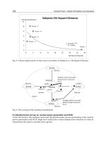
Figure 1 shows the matching extent for various maximum delivered temperatures of the
heat source. It can be found that 600
o
C can cover the maximum temperature requirement
530
o
C of step IV of the Cu-Cl cycle, but it does not have a sufficient heat percentage for step
IV, yet it provides surplus heat for steps 2 and 1. To satisfy the heat requirement of step IV,
the mass flow rate of heat transfer fluid must be increased. However, this may also deliver
surplus heat to other steps. As a result, the temperature exiting the Cu-Cl cycle will be
Water Splitting Technologies for Hydrogen Cogeneration from Nuclear Energy
453
increased and the overall thermal efficiency of both nuclear and hydrogen production plants
is hence decreased. Therefore, to increase the temperature entering the Cu-Cl cycle could be
a better option for satisfying the requirement. Figure 1 shows that the temperature of the
heat from the nuclear reactor entering the Cu-Cl cycle after a distant transport must be
around 650
o
C to match the heat requirements of the Cu-Cl cycle. In addition, the
temperature of heat transfer fluid leaving the nuclear reactor should be sufficiently high to
offset the heat losses in the transport pipeline between the nuclear and hydrogen production
plants, and also to avoid condensation or solidification on the inner wall of pipeline after
leaving the Cu-Cl cycle if the heat transfer fluid is steam or molten salt. An intermediate
heat exchanger that can heat a transfer fluid by the nuclear reactor coolant is suggested for
the heat supply to the hydrogen production plant due to the safety considerations of both
the nuclear reactor and hydrogen production plant, because the nuclear reactor coolant has
a risk to be contaminated by the chemicals of the Cu-Cl cycle if there is any leak in the pipe.
0
10
20
30
40
50
60
Step 4 Step 3 Steps 2 & 1
Percentage of heat flow, %
Required heat structure
Available Tmax: 650oC
Available Tmax: 600oC
Heat required by Cu-Cl cycle
A
vailable heat if deliverable T
max
is 650
o
C
A
vailable heat if deliverable T
max
is 600
o
C
Step IV, 530
o
C Step III, 375
o
C Steps II, I, 200
o
C
Fig. 1. Heat distribution of Cu-Cl cycle and nuclear heat source at various temperatures
3.3 Evaluation and selection of heat transfer fluids for heat transport in pipeline
Heat must be transferred by a heat transfer fluid flowing in a pipeline and transported from
a nuclear power station to a thermochemical hydrogen plant. On the basis of the heat
requirement per kilogram of hydrogen production shown in Table 5, the heat load can be
estimated according to the hydrogen production scale. Table 6 shows the estimate, where Q
T
is
the heat
load in the pipeline in units of MW
th
, i.e., megawatts of thermal energy.
When using sensible heat of the heat transfer fluid, the performance of the fluid can be
evaluated by the required flow rate for per unit heat quantity transported in the pipeline:
H
L
T
T
T
P
T
Q
X
CdT
at Q
T
= 1 MW
th
(6)
Nuclear Power – Deployment, Operation and Sustainability
454
where X
T
has the units of kg·s
-1
/MW
th
, and T
L
and T
H
are the inlet and outlet temperatures
of the heat transfer fluid that extracts heat from nuclear reactor coolant in the intermediate
heat exchanger. The values of T
L
and T
H
should prevent phase change and at the same time
allow a portion of heat losses in the transport pipeline. Also, C
P
is the heat capacity of the
heat transfer fluid that could be thermal oils, molten salts, supercritical water, steam, or
helium. To transport supercritical water, the transport pipeline must withstand a high
pressure (>22MPa), which is an engineering challenge for pipeline manufacturing and
maintenance. Thermal oil may experience coking and decomposition at a high temperature.
Solidification may occur in molten salt at low temperature spots. Steam may condense after
a distance of transport if the pressure is higher than its saturation point. The condensation of
steam indicates the need for an intermediate steam generator and two-phase flow in the
transport pipeline. This may significantly increase the construction capital and operating
cost. Therefore, in this chapter, the pressure of the steam is not suggested to be sufficiently
high such that the steam can remain in a gaseous state during circulation.
H
2
production scale, tonnes/day
100 200 400
Heat requirement by Cu-Cl cycle , MW
th
263 525 1050
Heat transport load (Q
T
) in pipeline, MW
th
316 630 1260
Table 6. Heat requirement and heat load in pipeline for various hydrogen production scales
Since step II of the Cu-Cl cycle has a temperature range of 80 - 200
o
C, it is assumed the
heating fluid exiting the step is 230
o
C. To avoid condensation, the pressure of the heating
fluid is 2 MPa, which is slightly lower than the saturation pressure of steam in case steam
serves as the heating fluid. For a comparable study, helium is designed to have the same
temperature and pressure as steam. Table 7 gives the values of X
T
, the suggested operating
parameters for the heat transfer fluids (helium, superheated steam, and molten salt), and the
thermodynamic properties of the fluids [Petersen, 1970; Wang, 2010]. Among the three
fluids of Table 7, both steam and molten salt have a phase change issue in the transport
pipeline, and molten salt has an issue of chemical stability when the temperature is high.
Therefore, helium is a comparatively good option for working as the heat transfer fluid.
Fluid in pipeline
Thermodynamic properties
(a)
X
T
kg·s
-1
/MW
th
P
MPa
Cp
kJ/kg·K
ρ
kg/m
3
k
w/m·K
Helium T
L
= 230
o
C 2 5.196 1.916 0.238 0.520
T
H
= 600
o
C 2 5.196 1.100 0.330
Steam T
L
= 230
o
C 2 2.735 9.495 0.042 1.189
T
H
= 600
o
C 2 2.247 5.010 0.081
Molten salt
(b)
230 600
o
C 0.1 1.549 1794 3.635 1.745
(a) Cp – heat capacity; ρ – density; k – thermal conductivity.
(b) Averaged values for the properties are used here due to the condensed state of molten
salt. For comparison purposes: 60% NaNO
3
and 40% KNO
3
; Melting point: 222
o
C; Boilin
g
point: 704
o
C.
Table 7. Values of X
T
, suggested operating parameters, and thermodynamic properties of
heat transfer fluids
Water Splitting Technologies for Hydrogen Cogeneration from Nuclear Energy
455
3.4 Flow characteristics of the heat transfer fluids in the transport pipeline
The heat loss of the transport pipeline is greatly influenced by the flow characteristics. The
flow parameters such as flow velocity and pressure loss must be controlled in an acceptable
engineering range in the pipeline. The velocity is determined by the flow rate and pipe
diameter. The flow rate can be calculated from X
T
and the heat load. Figure 2 shows the
dependence of helium flow velocity on the heat load and pipeline diameter. It can be found
that the velocity depends strongly on the pipeline diameter. Utilizing a smaller diameter
pipeline can reduce the construction cost. However, a smaller pipeline diameter may lead to
a higher velocity and larger pressure drop, which requires an increased pressure boosting
for the pipeline transport.
To estimate the pressure drop, the following equation is adopted:
2
1
2
Pu
f
LD
(7)
where ΔP/L is the pressure drop per unit length (Pa/m), D is the pipeline inside diameter, ρ
is the helium density (values given in Table 7),
u is the helium velocity (values given in Fig.
2),
f is the friction factor determined by the Reynolds number and the pipeline inner wall
roughness. Then from equations (6) and (7), the pressure loss can be calculated by:
2
252
14
2
TT
f
P
XD Q
L
(8)
Fig. 2. Dependence of helium flow velocity on the heat load and pipeline diameter
Figure 3 shows the dependence of pressure drop on heat load and pipeline diameter. For the
pipeline diameter of 1.0 m, the pressure loss may reach 500 kPa/km (5 bars/km) when the
heat load is 500 MW
th
(about 150 tons H
2
/day). To pump helium 10 km away, the pressure
Nuclear Power – Deployment, Operation and Sustainability
456
Fig. 3. Dependence of helium pressure drop on the heat load and pipeline diameter
loss is about 50 bars (5 MPa). This is a large pressure loss that may need significant
compressor work. To lower the pressure loss, the pipeline diameter must be increased or
multiple pipelines must be utilized.
3.5 Heat transport load and heat loss in the transport pipeline
When heat is transported by helium from a nuclear station to a hydrogen plant, it will
experience heat losses. The influencing parameters include the helium flow rate, heat load,
temperature, pipeline diameter, insulation, and weather conditions, among others. The heat
loss is transferred from helium to the pipeline wall mostly through convection, and then
through the conduction of the insulation of the pipeline, and lastly to air through convection
and radiation if the pipeline is on the ground surface. If the pipeline is buried underground,
the heat loss mostly goes to the soil. Since the thermal conductivity of metal is usually at
least one order larger than most types of soils, the soil can also serve as insulation if the soil
moisture is not significant. Due to the variations of soil types, buried depth and transport
length of pipeline, the investigation of the heat loss for underground pipelines is not
discussed in detail here. To simplify the evaluation, this paper will mainly examine the heat
loss of the surface pipeline.
Since the pipeline is sufficiently long compared with its diameter, the axial flow effect can be
neglected. The heat transfer can be approximated as a one-dimensional flow in the radial
direction. The heat loss per unit length of the pipeline can be calculated with the following
equation [Lienhard et al., 2008]:
2( )
ln( / ) ln[( ) / ]
11
()()
He air
oi o o
He air
pipe insu
i convec convec rad o
TT
Q
RR R R
L
kk
Rh h h R
(9)
where Q/L is the heat loss per unit length, T
He
is the average helium temperature in the
pipeline, T
air
is the air temperature varying with days and seasons, R
i
and R
o
are the pipeline
inside and outside radius (not including the insulation), k
pipe
is the thermal conductivity of
Water Splitting Technologies for Hydrogen Cogeneration from Nuclear Energy
457
the pipeline material, θ is the insulation thickness,
He
convec
h and
air
convec
h are the convection heat
transfer coefficients of helium flow in the pipeline and wind outside the insulation, and
h
rad
is the radiation heat transfer coefficient.
To have a safe design approximation, the upper value of the thermal conductivity of
insulation for a very high temperature environment (600
o
C) is adopted. It is also assumed
that the outer surface of the insulation will be oxidized after use of some time so that the
emissivity coefficient is higher than that of a well maintained condition. In addition, extreme
cold weather conditions may take place occasionally. Table 8 shows the parameters of the
pipeline, insulation and weather conditions for the calculation of heat losses.
Pipeline Insulation Air
Thermal conductivity Thermal conductivity Emissivity
T Wind speed
15 w/m·K 0.25 w/m·K 0.31 -50
o
C 6.0 m/s
Stainless Steel AISI
304L [Assael et al.,
2003]
Ceramic fiber blanket wrapped by heavily
oxidized aluminum foil [Desjarlais et al.,
2002; Engineeringtoolbox, 2010]
Ontario, Canada
[Ontario Government
Data, 2010]
Table 8. Parameters of pipeline, insulation and weather conditions for heat loss estimate
Figure 4 shows the estimated heat losses
for the heat transport loads of 200 - 700MW
th
. It can
be found that the heat loss can be controlled to below 2 MW
th
/km if the insulation thickness
0.0
1.0
2.0
3.0
4.0
5.0
6.0
7.0
8.0
9.0
10.0
0.00.51.01.52.02.53.0
Pipeline insulation thickness, m
Heat loss, MW
th
/km
0.5 m
1.5 m
2.0 m
X
T
= 0.52 kgs
-1
/MW
th
P = 2 MPa
T = 600
o
C
Pipeline diameter
Fig. 4. Heat losses of pipeline for the heat transport loads of 200 - 700MW
th
is larger than 1.0m. This suggests the key importance of the pipeline insulation. If
considering both the pipeline diameter (e.g. 1.0m) and insulation thickness (1.0m), the total
Nuclear Power – Deployment, Operation and Sustainability
458
diameter would be about 3.0m, which creates a barrier for animals and human activities if
the pipeline is constructed on the ground surface. To bury the pipeline underground is
another option. An underground pipeline will increase construction and maintenance costs.
Assume the cost of insulation is much lower than the pipeline so that the insulation
thickness can be constructed larger than 1.0 m. Then the heat loss of 2.0 MW
th
/km can be
considered as a typical value for the transport. When the heat load is higher, the heat loss
percentage is lower. When the pipeline length is 10 km, then the heat loss is 20 MW
th
. If the
heat load is 500 MW
th
(about 150 tonnes H
2
/day), the two-way heat loss is then about 12.5%.
However, Fig. 4 also shows the limit of heat loss reduction by insulation: to increase the
insulation thickness does not always have a significant heat loss reduction effect when the
thickness is larger than 1.5m. Considering the heat loss through pumps and other
components such as valves and expansion joints, the heat loss for a two-way transport
pipeline design is assumed below 20% when the transport distance from a nuclear reactor to
a hydrogen plant is within 10 km. The analysis shown in Table 6 of the former section is
based on this value.
4. Layout options for the integration of nuclear and hydrogen production
plants
When a nuclear reactor is coupled with a hydrogen production plant, the layouts for the
heat and fluid flows are important for safety and economics. The layout options depend
strongly on the reactor types. Since the indirect or reheat
cycle nuclear reactors have a
secondary coolant or circulation that can provide heat to the heating fluid of a hydrogen
plant through an intermediate heat exchanger, the integration of a hydrogen production
plant with an indirect or reheat cycle nuclear reactor may provide safer and more flexible
layout options. Therefore, the focus of this section will examine the direct cycle nuclear
reactors, which are represented by SCWR in this chapter.
Figure 5 shows the arrangement of a supercritical water-cooled nuclear reactor (SCWR) and
a hydrogen cogeneration plant with the Cu-Cl thermochemical cycle. The values of
temperatures and pressures of the flowchart were calculated according to the water stream
enthalpy change and expansion ratio that were reported in the past [Yamaji et al., 2005;
Naidin et al., 2009]. The streamlines for the supercritical water are based on existing fossil
fuel power plants that use a supercritical water turbine after changing the fossil fuel
combustion chamber and supercritical water tank to SCWR [Yamaji et al., 2005; Naidin et al.,
2009; Buongiorno et al., 2002]. The water stream circulation passing the lines A-B-C-D-E and
A-B-F-E in Figure 5 has the typical features of a no-reheat system that uses a preheater and
two types of turbines, i.e., high pressure (HP) and low pressure (LP) turbines. From the
temperatures shown in Figure 5, it can be found that point A, i.e., the location downstream
of the nuclear reactor but upstream of the turbines, can provide around 100
o
C of a driving
temperature difference for step IV of the Cu-Cl cycle that requires 530
o
C. At this location, a
bypass line of the supercritical water stream passing points A and N can be designed for
heat extraction from supercritical water to the Cu-Cl cycle. An intermediate heat exchanger
can be arranged on the line A-N-B to provide heat to helium that is used to heat the
hydrogen cycle through the circulation of H-I-J-K-L. For step III of the Cu-Cl cycle, the
temperature requirement is 375
o
C. The heat for this step can be supplied by the helium
stream exiting step IV that still has a temperature higher than 530
o
C at point I. The helium
stream exiting step III at point J still has a temperature higher than 375
o
C, so it can be used
for step II. Since step I of the Cu-Cl cycle needs electricity for electrolysis, the electricity can
Water Splitting Technologies for Hydrogen Cogeneration from Nuclear Energy
459
be conducted from the generator to the Cu-Cl cycle, as shown by the line passing points O
and M
As to the water stream for the power generation, there could be a number of preheaters, or
the water stream circulation could be designed as a multiple reheat cycle. The details of
these layouts will not be discussed in this chapter since these designs can provide multiple
options for the heat extraction bypass lines and the water stream circulation layout. Also, a
single reheat cycle layout, including its steam turbines and generator, is most widely
employed in current BWR and PWR technologies that can be applied to SCWR so as to
reduce the design complexity.
Fig. 5. Layout options for the integration of SCWR and Cu-Cl cycle (coolant passing through
high pressure and low pressure turbines in series)
5. Modulation of nuclear energy output and hydrogen cogeneration scale
The demand on power varies hourly, daily, monthly and seasonally on the power grid.
Figure 6 shows an actual power load profile on the power grid of a day (January 18, 2010) in
Nuclear Power – Deployment, Operation and Sustainability
460
Ontario, Canada [IESO, 2010]. It can be found that the power demand varies significantly at
different hours. The gap between peak and off-peak hours can even reach 70% of the base
power load. Since the power grid comprises various energy sources such as nuclear, fossil
fuels, hydro, solar and wind, the modulation of the power output from these sources is very
Fig. 6. Typical power load profile of a day in Ontario, Canada (January 18, 2010).
important. This means some power plants cannot operate at a constant power output. The
selection of energy sources to be adjusted upward to meet the peak power demand will
influence the amount of greenhouse gas emissions. To increase the nuclear power output for
the peak hour demand can reduce the greenhouse gas emissions, so there are some
countries employing and developing nuclear modulation technologies to adjust the power
output. The modulation technologies include the adjustment of control rod insertion depth,
the velocity of circulation steam, new types of grey rods, or a combination thereof [WNA ,
2011; Gilbert et al., 2004]. However, the adjustment of nuclear power output may directly
influence the operation of the nuclear reactor and introduce more safety issues than a
constant power output, so most countries use other energy sources such as fossil fuel and
hydroelectric power to follow the power demand on the grid. The percentage of nuclear
power in the base load in Figure 6 is maximized to lower the portions of other energy
sources. However, the base load varies monthly and seasonally, so the nuclear power plant
can rarely operate at its full design capacity of power generation, except if the nuclear
portion in the base load is small.
Using nuclear energy (either in the form of electricity or heat) to produce hydrogen at off-peak
hours and surplus generation capacity is a promising option. As shown in Figure 7, both the
heat and electricity outputs are controlled to be constant. The electricity delivered to the power
grid can follow the power load profile on the grid (either fully or partly), and the rest of the
electricity goes to conventional water electrolysis. This option has no requirement of
modulating the heat and electricity output of the nuclear reactor, but the hydrogen production
facilities must be able to accommodate the modulation of production rate.
Figure 8 shows another option that has no requirement of modulating the heat but must
modulate the electricity generator to accommodate varying heat input, and at the same time
Water Splitting Technologies for Hydrogen Cogeneration from Nuclear Energy
461
to modulate the hydrogen production rate. In both options, the total heat output from a
nuclear reactor is constant, so it is anticipated to be safer than the measure of varying heat
output. In comparison, option 1 is safer and more simple in principle, but the hydrogen
production efficiency with water electrolysis is lower than with thermochemical cycles in
option 2, which may influence the hydrogen production scale and economics.
Fig. 7. No modulation of both nuclear heat and electricity with water electrolysis
Fig. 8. No modulation of nuclear heat with thermochemical cycles
Table 9 shows the hydrogen production rate at different hours of a day. The values are
calculated on the basis of the design capacity of 1,000 MWe for a Generation IV single
supercritical water-cooled nuclear reactor (SCWR). The SCWR operates at its maximum
capacity with cogeneration of hydrogen. The available heat for hydrogen production is the
difference between the design capacity of the SCWR and the power generated that is
following the power demand profile of the power grid shown in Figure 6. The heat supplied
to the Cu-Cl cycle from SCWR for the thermochemical Cu-Cl cycle is assumed to have a loss
of 20% within 10 km, as discussed in the former section. The data in Table 5 is used to
determine the heat requirements of the Cu-Cl cycle. The overall efficiencies of water
electrolysis and the Cu-Cl cycle are assumed to be 30% and 45% respectively, which
suggests a smaller efficiency gap than shown in Table 2 so as to have a conservative
estimate. It can be found that a single SCWR at off-peak hours and surplus design capacity
can produce at least 100 tonnes of hydrogen each day. This production rate is equivalent to
the production capacity of an industrial plant with steam methane reforming, which is the
major technology employed today.
Nuclear Power – Deployment, Operation and Sustainability
462
Time
hour
Generated power and
design capacity
, MW
e
Available heat for H
2
production, MW
th
H
2
production rate
Tonnes/day
% of full
design
capacity
Generated
power
Unused
power
capacity
Unused heat
quantity
(a)
Water
electrolysis
Cu-Cl
cycle
1-5am 53% 530 470 1044 265 318
5-6am 56% 560 440 844 248 298
6-7am 62% 620 380 978 215 257
7-8m 66% 660 340 756 192 230
8-9am 70% 700 304 676 172 206
9am-16pm 74% 740 260 578 147 176
16-17pm 75% 750 250 556 141 169
17-18pm 78% 780 220 489 124 149
18-19pm 80% 800 200 444 113 136
19-20pm 78% 780 220 489 124 149
20-21pm 74% 740 260 578 147 176
21-22pm 66% 660 340 756 192 230
22-23pm 60% 600 400 889 226 271
23pm-1am 54% 540 460 1022 260 312
(a) The thermal efficiency of power generation is assumed to be 45% for SCWRs [Kirillov,
2008,
Yamaji, 2005; Naidin, 2009; Buongiorno, 2002].
Table 9. Hydrogen production scale and quantity with nuclear energy at various hours
6. Conclusions
This chapter examined the usage of nuclear energy for the cogeneration of electricity and
hydrogen with water splitting technologies, so as to improve the economics of power plants
and at the same time reduce greenhouse gas emissions. The hydrogen economy is discussed
and the reduction of greenhouse gas emissions by use of nuclear generated hydrogen as a
substitute of fossil fuels is quantified. The thermal efficiencies and economics of various
hydrogen production methods with nuclear energy are examined. The methods include
thermochemical water splitting cycles, conventional electrolysis, and high temperature
electrolysis. Among these methods, thermochemical cycles have the most promisingly high
efficiency and economics. It is found that the relatively high temperature requirements of
Water Splitting Technologies for Hydrogen Cogeneration from Nuclear Energy
463
numerous thermochemical cycles are the common threshold of utilizing nuclear heat to
produce hydrogen. The copper-chlorine (Cu-Cl) cycle has a minimum temperature
requirement (about 530
o
C) that can be met by most Generation IV nuclear reactors. The
temperature of a nuclear reactor should not only meet the threshold, but it should also
match the heat distribution of the thermochemical cycle. Also, the nuclear reactor
temperature must be high enough to offset the heat losses in the heat transport pipeline. The
future studies of thermochemical hydrogen production can be conducted toward lowering
the temperature requirements. An intermediate heat exchanger is suggested between the
nuclear reactor and thermochemical cycle so as to minimize the mutual influence between
the plants and improve the safety and operating flexibility.
Various heat transfer fluids for the heat exchange and transport pipeline were compared and
evaluated. Considering the heat transport complexity in the pipeline and the importance of
being chemically inert, phase change fluids and thermal oils are not suggested. Pressurized
helium is a promising option for serving as the long distance heat transport fluid in the
pipeline. A challenge of the heat transport in a pipeline is the pressure boosting requirement to
overcome the considerable pressure losses if the pipeline diameter is smaller than one meter or
the heat transport load is too large. Another challenge is the large diameter of the pipeline and
thermal insulation. In order to control the two-way heat loss below 20%, the diameter must be
larger than 3 meters (thermal insulation inclusive), which is a challenge for either
underground or surface transport. The overall layout options for the integration of nuclear
reactors and hydrogen production plants are also discussed, including the distant heat
transport from nuclear reactors to a hydrogen production plant. Direct cycle nuclear reactors
are discussed in more detail due to less flexibility than indirect cycle reactors.
The modulations of nuclear energy output and hydrogen cogeneration rates are also
discussed in this chapter. The energy output modes of nuclear reactors include constant and
variable output. Similarly, the hydrogen production scales also have two modes that are
determined by the modulated heat availability of the nuclear reactors. It is concluded that a
constant total heat output can be approached if the hydrogen is produced from
thermochemical cycles. A constant total electricity output can also be approached with
conventional water electrolysis. The constant energy output (either in the form of heat or
electricity) from a nuclear reactor can provide a load following pattern that can meet the
power load profile on the grid, so as to reduce the usage of fossil fuels for peak hours. The
thermal energy of a single Generation IV nuclear reactor at off-peak hours and surplus
design capacity are sufficient to power an industrial hydrogen plant with a thermochemical
cycle or water electrolysis.
7. Acknowledgements
Support of this research from Atomic Energy of Canada Limited and the Ontario Research
Excellence Fund is gratefully acknowledged.
8. References
Assael, M. J. & Gialou, K. (2003). Measurement of the Thermal Conductivity of Stainless
Steel AISI 304L up to 550 K.
International Journal of Thermophysics, Vol. 24, pp. 1145-
1153
Nuclear Power – Deployment, Operation and Sustainability
464
Buongiorno, J. (2002). The Supercritical-water-cooled Reactor (SCWR). American Nuclear
Society (ANS) Winter Meeting
, Washington DC, US, November 18, 2002.
de Jong, M; Reinders. A. H. M. E.l; Kok, J. B. W. & Westendorp, G. (2009) Optimizing a
Steam-methane Reformer for Hydrogen Production.
International Journal of
Hydrogen Energy
, Vol. 34, pp. 285 – 292
Desjarlais, A. O. & Zarr, R. R. (2002) Insulation Materials. Printed in Bridgeport, NJ, US.
ISBN 0-8031-2898-3. 2002, Vol. 4, pp. 122-128
Engineeringtoolbox (2010). The Radiation Heat Transfer Emissivity Coefficient of Some
Common Materials as aluminum, Brass, Glass and Many More. Available from
(Accessed on Oct 4, 2010): />coefficients-d_447.html
Forsberg, C. W. (2007). Future Hydrogen Markets for Large-scale Hydrogen Production
Systems.
International Journal of Hydrogen Energy, Vol. 32, pp. 431-439.
Forsberg, C. W. (2003).
Hydrogen, Nuclear Energy, and the Advanced High-temperature
Reactor.
International Journal of Hydrogen Energy, Vol. 28, pp.1073–1081
Forsberg, C. (2002). Hydrogen, electricity, and nuclear power.
Nuclear news, September
2002, pp. 30-31
Gilbert, M. M. (2004) Renewable and Efficient Electric Power Systems. ISBN: 978-0-471-
28060-6. Wiley-IEEE Press, August 11, 2004, pp. 135-148
Government of Alberta (2008). Electricity statistics. Available from (Accessed on May 20
th
,
2010):
IEA (International Energy Agency) (2010). Hydrogen Production & Distribution.
IEA Energy
Technology Essential
., Available from (Accessed on December 20, 2010):
IESO (Independent system operator) (2010). Ontario Demand on MW. Available from
(Accessed on November 26, 2010):
Jean-Pierre Py & Capitaine, A. (2006) Hydrogen Production by High Temperature
Electrolysis of Water Vapour and Nuclear Reactors.
16th World Hydrogen Energy
Conference
(WHEC16, 2006), June 13-16, Lyon, France.
Kirillov, P. L. (2008). Supercritical Water Cooled Reactors.
Thermal Engineering, Vol. 55, pp.
361-364
Kreith, F & Yogi Goswami, D. (2007). Handbook of Energy Efficiency and Renewable Energy.
Publisher: CRC press, ISBN: 9780849317309, ISBN 10: 0849317304, Chaper 6
Kubo, S.; Kasahara, S.; Okuda, H; Terada, A; Tanaka, N.; Inaba, Y.; Ohashi, H.; Inagaki, Y.;
Onuki, K. & Hino, R. (2004). A Pilot Test Plan of the Thermochemical Water-
splitting Iodine–sulfur Process.
Nuclear Engineering and Design , Vol. 233, pp. 355–
362
Lienhard IV, J. H.; Lienhard V, J. H. (2008) A Heat Transfer Textbook. 3
rd
edition, Phlogiston
Press, Cambridge, Massachusetts, USA, 2008, Chapters III and IV, pp. 341-594
Naidin, M., Mokry, S., Baig, F. & Gospodinov, Y. (2009). Thermal-Design Options for
Pressure-Channel SCWRS With Cogeneration of Hydrogen.
Journal of Engineering
for Gas Turbines and Power
, Vol. 131, pp. 012901-1~80
Water Splitting Technologies for Hydrogen Cogeneration from Nuclear Energy
465
Naterer, G.F. ; Fowler M.; Cotton J. & Gabriel K. (2008). Synergistic Roles of Off-peak
Electrolysis and Thermochemical Production of Hydrogen from Nuclear Energy in
Canada.
International Journal of Hydrogen Energy, Vol. 33, pp. 6849 – 6857.
NYSERDA (New York State Energy Research and Development Authority) (2010).
Hydrogen Fact Sheet: Hydrogen Production Steam Methane Reforming (SMR).
Technical report - Clean Energy Initiative., Available from (Accessed on May 1
st
,
2010):
/>steammethanereforming.pdf
Ontario government data (2010). Available from (Accessed on Oct 4, 2010):
Petersen, H (1970). The Properties of Helium: Density, Specific Heats, viscosity, and Thermal
Conductivity at Pressures from 1 to 100 bar and from Room Temperature
to about 1800 K.
Risö Report No. 224. Danish Atomic Energy Commission Research Establishment
Risö
. September, 1970.
Sadhankar, R. R,; Li, J.; Li, H.; Ryland, D. & Suppiah, S. (October 2005). Hydrogen
Generation Using High-temperature Nuclear Reactors.
55th Canadian Chemical
Engineering Conference
, Toronto
Schultz, K. (2003) Thermochemical Production of Hydrogen from Solar and Nuclear Energy.
Presentation to The Stanford Global Climate and Energy Project. 14 April, 2003.
General Atomics, San Diego, California, US. Also available from:
Sivula, K.; Zboril, R.; Le Formal, F.; Robert, R.; Weidenkaff A.; Tucek, J.; Frydrych, J. &
Grätzel, M. (2010). Photoelectrochemical Water Splitting with Mesoporous
Hematite Prepared by a Solution-Based Colloidal Approach. Journal of American
Chemical Society, Vol.
132, pp. 7436–7444
Steinfeld, A. (2005). Solar Thermochemical Production of Hydrogen – A Review.
Solar
Energy
. Vol. 78, pp. 603–615
Wang, Z. L. & Naterer, G. F. (2010). Greenhouse Gas Reduction in Oil Sands Upgrading and
Extraction Operations with Thermochemical Hydrogen Production.
International
Journal of Hydrogen Energy
, Vol. 35, pp. 11816-11828
Wang, Z.L.; Naterer G. F.; Gabriel, K.S.; Gravelsins, R. & Daggupati, V.N. (2010).
Comparison of Sulfur–iodine and Copper–chlorine Thermochemical Hydrogen
Production Cycles.
International Journal of Hydrogen, Vol. 35, pp. 4820 – 4830
Wang, Z. L.; Naterer, G. F.; Gabriel, K. S.; Gravelsins, R. & Daggupati, V. N. (2009).
Comparison of Different Copper-chlorine Thermochemical Cycles for Hydrogen
Production
. International Journal of Hydrogen Energy, Article in Press, Vol. 34, pp.
3267-3276
WNA (World Nuclear Association). Generation IV Nuclear Reactors. Available from
(accessed on December 20, 2010)
WNA (World Nuclear Accociation) (2011). Nuclear Power in France. Available from
(Accessed on March 20, 2011):
Nuclear Power – Deployment, Operation and Sustainability
466
Yamaji, A.; Kamei, K.; Oka, Y. & Koshizuka, S. (2005). Improved Core Design of the High
Temperature Supercritical-pressure Light Water Reactor.
Annals of Nuclear Energy,
Vol. 32, pp. 651–670
19
Reformer and Membrane Modules (RMM) for
Methane Conversion Powered
by a Nuclear Reactor
M. De Falco
1
, A. Salladini
2
, E. Palo
3
and G. Iaquaniello
3
1
Faculty of Engineering, University Campus Bio-Medico of Rome,
2
Processi Innovativi, L’Aquila,
3
Tecnimont KT S.p.A., Rome,
Italy
1. Introduction
In the last few years, significant developments in membrane science and the vision of
process intensification by multifunctional reactors have stimulated the academic and
industrial research focused on membrane reactor application to chemical processes (Mendes
et al., 2010, Dittmeyer et al., 2001, Basile et al., 2005a, De Falco et al., 2007). From these
works, the increase of the reactants conversion above the equilibrium values appears to be
possible when a reaction products at least is removed through the membrane. As stated in
the following, the integration of selective membrane in a chemical process can be twofold:
directly inside the reaction environment (Integrated Membrane Reactor – IMR);
after the reaction step (Reaction and Membrane Module – RMM).
In this chapter a methane steam reforming (MSR) RMM pre-industrial plant, designed and
tested to investigate at an industrial scale level the plant performance, is presented.
A major benefit of the proposed RMM configuration is the shift of steam reforming reactions
chemical equilibrium by removing the hydrogen produced at high temperature, thanks to
the integration of highly selective Pd-based membranes and enhancing the final product
yield. By this way, the process can operate at a temperature as low as 600-650°C in
comparison to 850-880°C needed in conventional plants, and enable the use of low
temperature heat source as helium heated in a nuclear reactor.
This chapter reports, firstly, membrane reactor concept, selective membrane typologies and
integration strategies; then it discusses the experimental data gathered over 1000 hours of
testing on an industrial pilot unit in terms of feed conversion at different operating
parameters and elaborates such data in order to optimize the overall architecture, defining
the maximum achievable feed conversion under different scenario of heat integration.
Finally, a membrane reactor perspectives analysis, mainly focused on integration with
nuclear reactors for steam reforming reactor heat duty supplying, is reported in order to
understand which technical and economical targets have to be reached in the next future for
a commercial diffusion.
The plant discussed in this chapter, placed in Chieti Scalo (Italy), is characterized by a H
2
design capacity of 20 Nm
3
/h and it operates with three Pd and Pd/Ag based membranes for
Nuclear Power – Deployment, Operation and Sustainability
468
hydrogen separation. It was developed in the framework of the Italian FISR Project “Pure
hydrogen from natural gas reforming up to total conversion obtained by integrating chemical
reaction and membrane separation”, which grouped Italian universities, and the engineering
society Tecnimont KT (TKT), cooperating in the development of each critical point of this
innovative technology, such as membrane manufacture and assembling and catalyst
optimization, resulting in the plant design and operation finally carried out by TKT. This
installation, the first of this type and size, makes it possible to completely understand the
potential of selective membrane application in industrial high-temperature chemical processes.
2. Membrane reactor concept and benefits
A membrane reactor (MR) is a system coupling reaction and separation of one or more
products, with the separation operation performed by a selective membrane. Although not
yet very used at industrial scale, MRs are attracting the attention of scientists and engineers
in the last two decades and many interesting papers have appeared in the literature on their
performance and possible applications in many fields of chemical and biochemical
industries. An excellent review about these topics has appeared in 2002 by Sanchez Marcano
& Tsotsis (Sanchez Marcano & Tsotsis, 2002). Moreover, the Italian company Tecnimont-KT
has developed and fabricated a membrane reactor methane steam reforming pre-industrial
prototype with a pure hydrogen production capacity of 20 Nm
3
/h (De Falco et al., 2011a)
and described in paragraph 3.
MR concept is based on the removal of a reaction product in order to avoid the reaction
equilibrium conditions to be achieved and promoting reaction kinetics.
Most of industrial chemical reactions are reversible reactions, thermodynamically limited
since equilibrium conditions cannot be overcome in the reacting mixture. From a
thermodynamic point of view, equilibrium is represented by a constraint, i.e. equilibrium
constant, on mole concentrations, temperature and pressure, derived from the second
principle of thermodynamics. When equilibrium conditions are achieved, no net change in
state variables is observed.
From a kinetics point of view it means that at equilibrium the reaction rate of the direct
reaction is equal to the reaction rate of the inverse reaction. Taking as reference an
elementary reversible reaction:
A ↔ B (1)
the kinetics scheme is characterized by a direct reaction rate (A → B) and an inverse reaction
rate (B → A). Initially, if only component A is fed to the reactor, the direct reaction is
promoted. Then, as the concentration of component B increases, the inverse reaction is
supported as far as the direct reaction and inverse reaction rates assumes a similar value
(equilibrium conditions) and reaction stops.
Integrating a selective membrane into the reaction environment allows to remove the
reaction product (B), avoiding the increase of inverse reaction and promoting the direct
reaction kinetics. By this way, two main benefits are reached:
removing one or more reaction products as they are generated allows to obtain
conversions higher than equilibrium values;
if the membrane is very selective with regard to a specific product, it is possible to
support reaction and product separation in one single compact device, obtaining a very
pure compound.