Advances in Modern Woven Fabrics Technology Part 12 potx
Bạn đang xem bản rút gọn của tài liệu. Xem và tải ngay bản đầy đủ của tài liệu tại đây (3.91 MB, 20 trang )
The Flame Retardant Nomex/cotton and Nylon/Cotton
Blend Fabrics for Protective Clothing
209
DMDHEU
(%)
LOI (%)
1 laundering 25 launderings 40 launderings 50 launderings
6 28.0 23.8 23.1 22.5
8 28.4 26.1 24.4 23.2
10 28.5 27.1 25.5 24.8
Table 10. The LOI of the nylon/cotton fabric (desert) treated with 32%HFPO and DMDHEU
at different concentrations and cured at 165C for 2 min. (The LOI (%) of the untreated fabric
is 20.1.)
DMDHEU
(%)
Char Length (mm)
1 laundering 25 launderings 40 launderings 50 launderings
6 68 >300 >300 >300
8 74 94 103 >300
10 53 81 92 92
Table 11. The vertical flammability of the nylon/cotton fabric (desert) treated with
32%HFPO and DMDHEU at different concentrations and cured at 165C for 2 min. (The
char length of the untreated fabric is >300 mm.)
The nylon/cotton fabric (woodland) is treated with 32% HFPO and DMDHEU at different
concentrations and subjected to 1 laundering cycle. The tensile strength of the fabric thus
treated after 1 laundering cycle is shown in Table 12. When DMDHEU concentration
increases from 2 to 8%, the tensile strength at the warp direction is in the range from 703 N
(98% retention) to 685 N (95% retention), respectively. The tensile strength in the filling
direction is in the range from 445 N (97 retention) to 454 N (99% retention). Thus, the data
presented in Table 12 demonstrate that the fabric treated with HFPO and DMDHEU has
negligible strength loss. More details for the flame retardant finished nylon/cotton blend
fabrics can be found in our two recent publications [20, 21].
DMDHEU (%)
Tensile Strength (N) Tensile Strength Retention (%)
Warp Filling Warp Filling
2 703 454 98 99
4 694 449 96 98
6 685 445 95 97
8 701 451 97 98
Control 721 458
Table 12. The tensile strength of the nylon/cotton fabric (woodland) treated with 32%HFPO
and DMDHEU at different concentrations and cured at 165C for 2 min (after 1 laundering
cycle).
4. Conclusions
(1) The HFPO/BTCA/TEA flame retardant finishing system applied to the Nomex/cotton
blend fabric significantly enhances the performance of the Nomex/cotton blend fabric. The
Advances in Modern Woven Fabrics Technology
210
Nomex/cotton blend fabric treated with HFPO/BTCA/TEA is able to achieve high levels of
the flame retardant performance and laundering durability at relatively low add-on levels.
The treated fabric also shows modest strength loss and little change in hand properties. This
flame retardant finishing system is a formaldehyde-free and odor-free system.
(2) DMDHEU is able to covalently bond HFPO to nylon 6.6 fabrics probably by the
formation of a crosslinked HFPO/DMDHEU polymeric network. The combination of HFPO
and DMDHEU is an effective durable flame retardant finishing system for the 50/50
nylon/cotton blend BDU fabrics with negligible fabric strength loss. The MDPA/TMM
system is not suitable for the flame retardant finishing of the nylon/cotton blend fabric.
5. Acknowledgement
This paper is based on the data included in the dissertation of Dr. Hui Yang, the University
of Georgia. Dr. Hui Yang was a graduate student under my supervision and he received his
Ph.D. degree in the summer of 2007.
6. References
[1] Rebouillat, S. High Performance Fibers, Woodhead Publishing, Cambridge, U.K., pp23-61
(2001).
[2] Schutz, H. G., Cardello, A. V., Winterhalter, C. Textile Research Journal, 75: 223-232 (2005).
[3] Fukatsu, K. Polymer Degradation and Stability, 75: 479-484 (2002).
[4] Tesoro, G.C.; Rivlin, J. J. AATCC, 5(11):23-26 (1973).
[5] Wu, W.D., Yang, C.Q. Journal of Fire Science, 22:125-142 (2004).
[6] Yang, C. Q., Xu, Y. Wu, W.D. Fire and Materials, 29:109-120 (2005).
[7] Yang, H., Yang, C. Q. Polymer Degradation and Stability, 88:363-370 (2005).
[8] Wu, W.D., Yang, C. Q. Polymer Degradation and Stability, 91:2541-2548 (2006).
[9] Wu, W.D., Yang, C. Q. Polymer Degradation and Stability, 92:363-369 (2007).
[10] Wu WD, Yang CQ. Polymer Degradation and Stability, 85:623-632 (2004).
[11] Yang, C. Q., Wu, W.D. Fire and Materials, 27: 223-237 (2003).
[12] Yang, C. Q., Wu, W.D. Fire and Materials, 27: 239-25 (2003).
[13] Levchik, S. V., Weil, E. D., Polymer International, 49:1033-1073 (2000).
[14] Subbulakshmi, M. S., Kasturiya, N., Hansraj, B. P., Agarwal, A. K., Journal of
Macromolecular Science, Reviews in Macromolecular Chemistry and Physics, C(40):85-
104 (2000).
[15] Lewin, M., In: Lewin, M., Sello, S. B., (ed.), Handbook of Fiber Science and Technology:
Chemical Processing of Fibers and Fabrics, Vol.2, Part B, New York, Mercel Dekker,
pp.117-120 (1984).
[16] Weil, E. D., Levchik, S. V., Journal of Fire Science, 22:251-264 (2004).
[17] Horrocks, R. A., In: Heywood, D., editor, Textile Finishing. Society of Dyers and
Colorists, West Yorkshore, U.K., pp.214-250 (2003).
[18] Kang, I., Yang, C. Q., Wei, W., Lickfield, G. C. Textile Research Journal, 68:865-870 (1998).
[19] Yang, H., Yang, C. Q., Journal of Fire Science, 25:425-446 (2007).
[20] Yang, H., Yang, C. Q., Industrial and Engineering Chemistry Research, 47:2160-2165 (2008).
[21] Yang, H., Yang, C. Q., He, Q., Polymer Degradation and Stabilization, 94:1023-1-31 (2009).
11
Liquid Transport in Nylon 6.6. Woven Fabrics
Used for Outdoor Performance Clothing
A. B. Nyoni
National University of Science and Technology,
Department of Textile Technology
Zimbabwe
1. Introduction
Humans rely on the evaporation of sweat to remain comfortable and prevent overheating in
hot environments and during exercise.
1
Discomfort results from the build up of sweat on the
skin and if it doesn’t evaporate quickly, the body core temperature heats up producing more
sweat exposing the wearer to potential afflictions such as post-exercise chill and even
hypothermia. Therefore, with properly engineered dynamic or responsive fabrics
2,3
less
energy to cool the body will be required resulting in increased performance and endurance.
Researchers
4,5
generally agree that liquid transport properties are significantly affected by
fibre type, yarn construction and fabric construction. The fibre length, width, shape and
alignment all have a great influence on the quality of the capillary channels in the inter-fibre
spaces and size of the pores present. The density and structure of yarns can greatly influence
the dimensions and structure of inter- and intra-yarn pores
4
and pore sizes and distribution
are determined by the manner in which fibres are assembled into the woven, nonwoven, or
knitted structure.
6
Finishing treatment of the fabric surface and its surface roughness and
the bulk properties of the liquid (i.e. viscosity, surface tension, volatility and stability) also
play a significant role during wicking.
Additional important variables which exert influence on wicking are the level of physical
activity and environmental conditions such as the relative humidity of the atmosphere
which combined with the ambient temperature, determine the water vapour pressure of the
ambient atmosphere and hence the rate of water vapour transfer through clothing. The wind
speed which affects the thermal and water vapour resistance of the air adjacent to the fabric
also plays a significant part during wicking.
7
Therefore, to design textile materials with
specific functional properties of moisture management, it is essential to establish the
relationship between the wicking properties of yarns and the structure of the fabric they are
part of. In this chapter the effect of these variables on the wicking performance of a selected
fabrics made from a combination of textured and flat continuous Nylon 6.6 yarns
8
were
determined by The Longitudinal Wicking “Strip” Test using BS3424 Method 21 (1973).
In all the fabrics, saturated, unsaturated and dry zones were exhibited and the
simultaneously occurrence of wetting, wicking, liquid dispersion and evaporation
influenced the time exponent values k obtained.
The critical volume of liquid at which transfer wicking occurred at yarn cross over regions
termed as the “transfer rate” was influenced by two competitive effects, i.e. the tendency to
Advances in Modern Woven Fabrics Technology
212
spread in the capillary space between the filaments of “absorber” textured yarns and the
tendency to wick the liquid by the “runner”flat continuous filament yarns yarns
2. Fabric sample preparation and test methods
Fabrics woven from different combinations of nylon 6.6 filament yarns were selected and
the characteristics determined as shown in Table 1.
Prior to testing, the samples were conditioned in a standard atmosphere of 20±2ºC and
65±2% relative humidity for 24 hours. Sample strips of 3.5cm x 33cm each were cut in the
warp and weft directions from the conditioned sample. To aid observation of the wicking
distance, a pen filled with water soluble ink was used to mark a graduated scale in 1cm
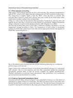
intervals on the strips. The samples were then mounted on the pinned frame for the vertical,
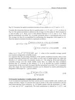
horizontal and syphon tests as shown in Figures 1, 2 and 7 respectively. The dipping ends of
the samples were aligned leaving a length of 1cm to dip into the infinite reservoir containing
distilled water. A ruler with millimeter divisions was placed parallel to the sample strip to
enhance the accuracy of the measurement.
For washed fabric tests, the fabric samples were washed with a non-biological detergent in
an automatic front loading domestic washing machine and tumble dried according to the
ISO 6330:2000 which specifies domestic washing and drying procedures for textile testing.
The dry fabrics were then conditioned in a standard atmosphere of 20± 2°C and 65±2%
relative humidity for 24 hours before testing. Sample strips of 3.5cm x 33cm each were cut in
the warp and weft directions from the conditioned fabric sample and tested with the frame
in both the vertical and horizontal positions above the water basin containing distilled water
and the results are shown in Table 2.
Fig. 1. Vertical Strip Wicking Test
Liquid Transport in Nylon 6.6. Woven Fabrics Used
for Outdoor Performance Clothing
213
The height of the advancing liquid front as a function of time was recorded by visual
observation of the running ink through a travelling microscope at 5 minutes intervals for the
first hour, and then at hourly intervals thereafter until the maximum wicking height
(equilibrium point) was reached. To avoid contamination by the indicating ink the test
liquid was changed after each test. Constant temperature and humidity in the ambient
atmosphere were achieved by testing in the conditioned room.
The strip method has been used by Hollmark and Peek
9
to characterize the wicking
behaviour of porous materials and they found it readily applicable under different
conditions with a relatively high degree of reproducibility. Zhuang
10
also found good
correlation between results obtained by manual and automatic testing.
3. Vertical strip wicking test results
3.1 Fabric sample S1F–unwashed
The results obtained from the wicking tests are shown in Table 2 and in Figures 3. Figure 3
shows that there was rapid wicking for the first 5-10 minutes in both the warp and weft
directions and then a significant decrease to a slow rate with the lapse of time until it was
difficult to note the level of liquid rise in 5 minutes time intervals. Observations done at
hourly intervals thereafter tabulated in Table 2 indicate that from 60-180 minutes the fabrics
continued wicking at a slow rate until an equilibrium point was reached.
Property Test Method Sample S1F Sample S2F
Ends/cm BS 2862:1984 70 70
Picks/cm BS 2862:1984 30 50
Linear Density
Warp (dtex)
BS 946:1970
44dtexf34
flat fully dull PA 6.6
44dtexf34
flat fully dull PA 6.6
Linear Density
Weft (dtex)
BS 946:1970
195dtexf170
Airjet Textured
Bright PA6.6
44dtexf34
flat fully dull PA 6.6
Fabric Weight
g /
2
m
BS 2471:1978 43.75
26.31
Filaments x-section Microscopy-SEM Circular Circular
Warp
FilamentØ
Weft
Microscopy-SEM
11.673μm
11.673μm
11.673μm
11.673μm
Table 1. Fabric and Yarn Characteristics
Multiple comparison between means of the actual liquid advancement in the first 15minutes
(1
st
Quarter) Table 3 and the second 15 minutes (2
nd
Quarter) Table 4 of the hourly test
shown in Tables 5 indicate that that there was a significant difference in the distance moved
by the liquid in both the warp and weft direction wicking with the lapse of time. Wicking in
the weft direction was more rapid than in the warp direction and multiple comparison of
the actual liquid advancement in the first 15minutes (1
st
Quarter) of the hourly test in Tables
5 show that there was a significant difference in warp and weft direction wicking.
Microscopic examination of fabrics during wicking exhibited an almost linear leading edge
in the weft direction and a spiked pattern in the warp direction.
Advances in Modern Woven Fabrics Technology
214
Note: Figures in parentheses indicate the actual liquid advancement per time interval
Key: Uw-Unwashed
W-Washed
Table 2. Fabric Vertical and Horizontal Wicking Test Results
Key: Uw-Unwashed
W-Washed
Table 3. Fabric Wicking Test 1
st
Quarter (15 minutes).
Liquid Transport in Nylon 6.6. Woven Fabrics Used
for Outdoor Performance Clothing
215
Key: Uw-Unwashed
W-Washed
Table 4. Fabric Wicking Test 2
nd
Quarter (30 minutes).
Fabric samples Significance Difference
V15min-warp-uw Vs.
V15min-weft-uw
H15 min-warp-uw
V15min-warp-w
V30 min-warp-uw
0.000↑
0.000↑
0.000↑
0.000
***
***
***
***
V15min-weft-uw Vs.
H15 min-weft-uw
V15min-weft-w
V30 min-weft-uw
0.000↑
0.000↑
0.000
***
***
***
H15min-warp-uw Vs.
H15min-weft-uw
H15 min-warp-w
H30min-warp-uw
0.000↑
0.002↑
0.000
***
***
***
H15min-weft-uw Vs.
H15 min-weft-w
H30min-weft-uw
0.000↑
0.000
***
***
W = Washed fabric W = Unwashed fabric
H = Horizontal wicking V = Vertical Wicking
↑= Wicking decrease = Wicking increase
Significance of differences of fabric wicking:
***P≤ 0.001,**P≤0.01,*P≤0.05 and Not significant (ns) at P>0.05.
Table 5. Multiple Comparison Between Wicking Means of Fabric S1F
Advances in Modern Woven Fabrics Technology
216
Fabric samples Significance Difference
V15min-warp-uw Vs.
V15min-weft-uw
H15 min-warp-uw
V15min-warp-w
V30 min-warp-uw
0.000
0.000
0.000↑
0.000
***
***
***
***
V15min-weft-uw Vs.
H15 min-weft-uw
V15min-weft-w
V30 min-weft-uw
0.000
0.000↑
0.000
***
***
***
H15min-warp-uw Vs.
H15min-weft-uw
H15 min-warp-w
H30min-warp-uw
0.000
0.000↑
0.000
***
***
***
H15min-weft-uw Vs.
H15 min-weft-w
H30min-weft-uw
0.000↑
0.000
***
***
W = Washed fabric UW = Unwashed fabric
H = Horizontal wicking V = Vertical Wicking
↑= Wicking decrease
= Wicking increase
Significance of differences of fabric wicking:
***P≤ 0.001,**P≤0.01,*P≤0.05 and Not significant (ns) at P>0.05.
Table 6. Multiple Comparison Between Wicking Means of Fabric S2F
3.2 Vertical wicking fabric sample S2F-unwashed
The results in Table 2 and Figures 4 to 5 show that there was rapid wicking for the first 5-
10minutes in both the warp and weft directions which became less rapid with the lapse of
time. Multiple comparison of wicking results in Table 6 show a significant decrease in weft
direction wicking compared to warp direction wicking. The wicking rate significantly
decreased to a slow rate with the lapse of time in the warp and weft directions. The rapid
attainment of the equilibrium point when wicking the fabrics in the warp and weft direction
indicates that the liquid is rapidly spread over a large area for quick evaporation.
4. Horizontal strip wicking tests
Wicking occurs when a fabric is completely or partially immersed in a liquid or in contact
with a limited amount of liquid such as a drop placed on the fabric. In a vertically held
substrate, wicking is affected by gravitational forces and ceases when capillary forces are
balanced by the hydrostatic head.
11
At that point, the capillary pressure that raises the liquid
is balanced by the effect of gravity, that is, by the weight of raised liquid.
12
To determine the
extent to which gravity affects wicking, horizontal wicking tests were carried out on nylon
6.6 fabrics samples S1F and S2F and the results are shown in Table 2.
4.1 Horizontal strip wicking test sample S1F-unwashed fabric
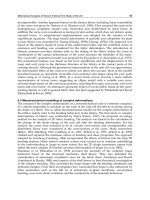
The results in Table 2 and Figures 3 to 6 exhibited a similar wicking trend as fabrics wicked
in the vertical direction in which wicking in the weft direction was more rapid than in the
Liquid Transport in Nylon 6.6. Woven Fabrics Used
for Outdoor Performance Clothing
217
Fig. 2. Horizontal Wicking Test
warp direction. However, even though the trend was similar, there was a significant
difference in the distance travelled by the wicked liquid compared to vertically wicking in
both the warp and weft directions as shown by the results of multiple comparison of the
actual liquid wicked during the 1
st
and 2
nd
quarters of an hourly test in Table 5. As was the
case with vertical wicking, there was rapid wicking for the first 5-10 minutes in the warp
and weft directions.
Fig. 3. Wicking test of fabric S1F – unwashed fabric
Advances in Modern Woven Fabrics Technology
218
4.2 Horizontal strip wicking test-sample S2F-unwashed fabric
Table 2 and Figures 4 and 5 shows that there was rapid wicking for the first 5-10 minutes
but wicking in the warp direction was more rapid than wicking in the weft direction. At the
start of wicking there is a variation in lift off followed by the same wicking trend in both the
weft and warp directions. Results of multiple comparison of the actual liquid wicked within
the 1
st
and 2
nd
quarters of an hourly test in Table 5 show a significant decrease in the liquid
wicked in both the warp and weft horizontal directions.
Fig. 4. Actual Liquid Advance Sample S1F - Unwashed Fabric
Fig. 5. Wicking Tests of Fabric S2F-Unwashed Fabric
Liquid Transport in Nylon 6.6. Woven Fabrics Used
for Outdoor Performance Clothing
219
Fig. 6. Actual Liquid Advance S2F-Unwashed Fabric
5. Syphon wicking
It is a known fact that the liquid flow in downward wicking is aided by gravity and occurs
more rapidly through an already saturated fabric with a lower resistance to flow than an
initially dry fabric.
13
A further study to determine the extent to which the structure of the
constituent yarns affects wicking in fabrics S1F and S2F was carried out by wicking washed
fabrics in the warp and weft directions using the Syphon
11
Test Method.
In downward wicking, Figure 7 a rectangular strip of the test fabric is used as a syphon, by
immersing one end in a reservoir of water or saline solution and allowing the liquid to drain
from the other end at a lower level, into a collecting beaker. The amount of liquid
transferred at successive time intervals can be determined by weighing the collecting
beaker. No published standards exist and evaluation of results differ between researchers
with some authors
14
taking the rate of mass transfer of the liquid when a constant flow
through the syphon has been attained as an indicator of wickability.
Hardman
14
distinguished this as a “rate of drainage,” using the elapsed time between the
initial moment of contact between the fabric strip and liquid and the moment when
dripping from the lower fabric end commences as a measure of wicking.
Because of the limited amount of liquid retained by the fabrics S1F and S2F due to the effects
of rapid evaporation observed in preceding experiments, determination of their downward
wicking behaviour was done by observing the actual distance traveled by the liquid towards
the bottom end of the fabric as a function of time.
Samples were prepared as in section 2 and the rectangular strip of the test fabric used as a
syphon by immersing 1cm of the top end in the liquid reservoir. The distance of water travel
as a function of time was taken at 5 minutes intervals for an hour or terminated when the
liquid dripped at the bottom of the fabric or when wicking ceased due to evaporation.
Advances in Modern Woven Fabrics Technology
220
A-liquid reservoir
B/C Strips of Fabrics
D-Ruler
E-Collecting tray
Fig. 4.7. Syphon Wicking Test
5.1 Syphon wicking test- fabric sample S1F and S2F
The results in Tables 7 show the distance travelled by the liquid leading front and the
figures in parentheses indicate the actual liquid advancement per time interval.
Fabric sample S1F made from 195f170 weft yarn and 44f34 warp yarn with 70 ends/cm and
30 picks/cm (43.75g/m
2
) was wicked in the warp and weft directions. Figure 8 shows that
after wicking fabric sample S1F for 50 minutes in the weft direction, the liquid had travelled
to the lower end of the fabric strip whereas in the warp direction the leading head was still
202mm from the lower end of the fabric.
When the fabric is wicked in the warp direction, the textured weft yarns cause retardation of
the liquid’s progress due to their absorption capacity. The absorption of the liquid into the
heterogeneous structure of the yarn causes a temporary slowing down of its advancement
as it is dispersed in the yarn structure before a critical volume is achieved
15
to enable liquid
transfer to the capillaries of the warp yarns. The nature of the liquid flow in the warp
direction therefore is in fast-slow fast (warp-weft-warp) steps resulting in a haphazard flow
as shown in Figure 9. In wicking the fabric in the weft direction, the high volume textured
weft yarns rapidly flood the capillaries of the flat continuous filament yarns and this speeds
Liquid Transport in Nylon 6.6. Woven Fabrics Used
for Outdoor Performance Clothing
221
Sample
S1F-Warp direction
(
l -mm)
S1F-Weft direction (
l -
mm)
S2F-Warp direction
(
l -mm)
S2F-Weft direction (
l -
mm)
Wicking
Time-t
minutes
Vertical
Syphon
Vertical
Syphon
Vertical
Syphon
Vertical
Syphon
5
35
35
70
42
37
58
25
48
10
45 (10)
47(12)
100(30)
84(42)
45 (8)
69(11)
32 (7)
56(8)
15
55 (10)
60(13)
119(19)
129(45)
49 (4)
74(5)
39 (7)
62(6)
20
62 (7)
69(9)
130(11)
156(27)
50 (1)
79(5)
41 (2)
67(5)
25
67 (5)
78(9)
140(10)
199(43)
51 (1)
81(2)
43 (2)
70(3)
30
70 (3)
98(20)
146 (6)
220(11)
53 (2)
82(1)
44 (1)
71(1)
35
72 (2)
110(12)
153 (7)
253(33)
54 (1)
84(2)
44 (0)
73(2)
40
73 (1)
116 (6)
157 (4)
268(15)
55(1)
84(0)
-
-
45
74 (1)
122(6)
158 (1)
282(14)
55(0)
-
-
-
50
75 (1)
128(6)
158 (0)
330(48)
-
-
-
-
55
79 (4)
139(11)
163 (5)
-
-
-
-
-
60
80 (1)
150(11)
165 (2)
-
-
-
-
-
120
89 (9)
-
180(15)
-
-
-
-
-
180
89 (0)
-
180 (0)
-
-
-
-
-
Note:Figures in parentheses indicate the actual liquid advancement per time interval.
Table 7. Washed Fabric Wicking Tests-Vertical Vs. Syphon Wicking
Advances in Modern Woven Fabrics Technology
222
the rate of wicking. The actual advancement of the wicked liquid shown in Figure 9 is
directly proportional to the wicking time in both cases (warp and weft) but was found to be
61% more in the weft compared to warp direction wicking. This indicates that for this fabric,
the wicking rate does not only depend on the yarn and fabric structure but also on the
direction of orientation of the constituent yarns in the structure.
Results in Table 7 show the wicking behaviour of an almost balanced fabric sample S2F
made from 44f34 warp and weft flat continuous filament yarns with 70 ends/cm and 50
picks/cm (26.31
2
/
g
m ). The graphical representation in Figures 10-11 plotted from the
results tabulated in Table 7 show that the rate of warp and weft wicking follow a similar
trend. The difference of the actual liquid wicked was 15% more in the warp direction due to
the high number of ends/cm compared to picks/cm therefore the packing of the additional
filaments in the warp yarns introduced more capillary spaces between the nylon filaments.
Due to its light-weight (26.31
2
/
g
m ), the fabric allowed rapid liquid evaporation. Results in
Table 7 show that the wicking rate had significantly slowed down after 20 minutes despite
the fact that the liquid flow in this test was through an already saturated fabric with a lower
resistance to flow and was also aided by gravity. After 35minutes wicking, liquid
advancement had ceased and when the fabric was left to wick to the end of the hour there
was no change in the position of the liquid edge. In the absence of gravity, this indicates that
there is significant rapid evaporation of liquid from the fabric which is a desired functional
property of fabrics designed to rapidly transmit perspiration to the exterior where it can
evaporate.
Fig. 8. Vertical Vs Syphon Wicking Fabric S1F-Washed
Liquid Transport in Nylon 6.6. Woven Fabrics Used
for Outdoor Performance Clothing
223
Fig. 9. Actual Liquid Advance-Vertical Vs. Syphon Wicking Fabric S1F-Washed
Fig. 10. Vertical Vs. Syphon Wicking-Fabric S2F-Washed
Advances in Modern Woven Fabrics Technology
224
Fig. 11. Actual Liquid Advance: Vertical Vs. Syphon Wicking Fabric S2F-Washed
6. Wicking characteristics of washed fabrics
The ability of a fibre to facilitate migration of liquid water or water vapour molecules depends
on its surface hydrophilicity or affinity for water, the textile finish applied and the fibre
substrate.
7,16
The surface properties of man-made fibres are generally adjusted with spin
finishing agents during the fibre spinning process.
17
Hydrophobic fibres can be modified in
finishing to give surface properties which can allow liquid flow.
18
Leijala and Hautojarvi
17
using Scanning Force Microscopy (SFM) studied the structure, distribution, and composition
of spin finish layers on a polypropylene fibre surface. They noted that the coverage and
homogeneous distribution of the finish on the fibre surface even though only a few
nanometers in thickness is an important factor affecting tribological and antistatic properties as
well as the wettability of fibres. In another study
14
, the wickability attributed to the
conventional (non porous) acrylic as was found to be the case with polypropylene was due to
spin finish which could be easily removed by washing. Gogalla
4
also noted that the uneven
distribution of chemical finish on the surface of a fabric greatly affected its wicking behaviour.
Electron micrographs of yarns from which the fabric samples S1F and S2F were woven in
Figure 12 a-c show traces of spin finish on all the yarns which was removed during the
scouring process.
During use, out-door and performance textiles fabrics are exposed to soiling which comes
from two different sources, namely,
a. from the body of the wearer and
b. from the environment.
therefore, it will be necessary at some stage to wash the fabrics. However, it is important
that such a treatment does not alter the functional properties of these garments. Therefore, it
Liquid Transport in Nylon 6.6. Woven Fabrics Used
for Outdoor Performance Clothing
225
was of interest to study the effect of laundering on the wicking behaviour of fabric samples
S1F and S2F.
(a) Sample S1Y 44F34 Flat Fully Dull PA 6.6 (b) Sample S2Y 33F34 Flat Fully Dull PA 6.6
(c) Sample S3Y Air Textured Bright PA6.6
Fig. 12. Nylon 6.6 Yarn Micrographs
Advances in Modern Woven Fabrics Technology
226
6.1 Results and discussion
6.1.1 Vertical wicking sample S1F- washed fabric: Warp and weft directions
Figures 17 to 20 show the graphical representation of the wicking rate of the washed and
unwashed fabrics plotted from results in Table 2. Multiple comparison of the fabric wicking
behaviour after a single wash in Table 5 show that there was a significant increase in the
wicking rate of sample S1F in both the vertical and horizontal directions. In all cases, the
weft direction wicking rate of washed fabrics remained higher than warp direction wicking
regardless of the orientation of the fabrics as was the case with the unwashed fabric.
6.1.2 Vertical wicking sample S2F -washed fabric: Warp and weft directions
Table 2 and Figures 23 to 24 show the vertical wicking results of sample S2F. Results in
Table 6 show that there was a significant increase in wicking in both directions after the
fabrics were washed. Wicking in the warp direction was more rapid than in the weft
direction and the difference gradually decreased with the lapse of time.
6.1.3 Horizontal wicking of washed fabrics
Fabrics wicked in the horizontal direction (Table 2 and Figures 13 and 19) show a similar
change in wicking trend as the fabrics wicked in the vertical direction. Figures 15 to 18 show
that there was marked increase in the wicking rate of samples S1F and S2F after a single wash.
Results of multiple comparison of the actual liquid wicked within the 1
st
and 2
nd
quarters of
an hourly test for fabric S2F exhibited a significant decrease in the liquid wicked in the
horizontal direction compared to wicking in the vertical direction. This deviation from the
general trend that horizontal wicking leads to a significant increase in wicking could not be
explained.
Fig. 13. Wicking Tests Sample S1F- Washed Fabric
Liquid Transport in Nylon 6.6. Woven Fabrics Used
for Outdoor Performance Clothing
227
Fig. 14. Actual Liquid Advance Sample S1F-Washed Fabric
Fig. 15. Wicking Tests Sample S2F-Washed Fabric
Advances in Modern Woven Fabrics Technology
228
Fig. 16. Actual Liquid Advance Sample S2F- Washed Fabric
Fig. 17. Wicking Tests Sample S1F-Washed Vs. Unwashed Fabrics