Advances in Satellite Communications Part 12 potx
Bạn đang xem bản rút gọn của tài liệu. Xem và tải ngay bản đầy đủ của tài liệu tại đây (1.05 MB, 15 trang )
Advances in Satellite Communications
154
The horizontal polarization, i.e. the TE01 mode at the common port is instead coupled to the
side arm (fundamental mode of port 4) only. Indeed, the same polarization is under cut-off
at port 3. As a consequence, ports 3 and 4 are also isolated as far as their fundamental mode
is concerned.
A careful design of the various geometrical parameters is required in order to obtain an
OMT with a suitable matching level. The side-arm coupling can be also performed on the
other orthogonal side of the common waveguide with a different orientation of the coupled
waveguide i.e. E-plane coupling instead of H-plane coupling. Anyway, this simple compact
configuration only works in quite narrow frequency bands. Proper matching structures such
as septa, irises and steps can be added to enlarge the operative frequency band up to 20%
(Dunning, et al. 2009) or to obtain a dual-band component (Rebollar, 1998). However,
proper care should be taken in order not to impair the power handling of the structure.
Moreover, the bandwidth limit of this configuration is related to the excitation of the higher
order modes TE11 and TM11 owing to the one-fold symmetry of the structure.
5.2 Boifot OMT
The Boifot junction has been introduced in order to obtain an OMT with a large operative
bandwidth (Boifot, 1990). As can be seen in Fig. 5.3, a symmetric E-plane coupling is
exploited for the horizontal polarization in order to obtain a two-fold symmetry of the
whole structure. This feature avoids the excitation of the TE11 and TM11 higher-order
modes in the common waveguide. In this way, the operative frequency band of the device
can be extended above the cutoff frequency of these modes up to the TE20 cutoff. The two
symmetric side arms have to be combined using both straight and bent rectangular
waveguide sections to obtain a single signal at port 4. The corresponding structure is
therefore more complex than an OMT with a single side arm.
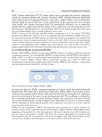
Fig. 5.10. Scheme of the Boifot OMT.
Passive Microwave Feed Chains for High Capacity Satellite Communications Systems
155
A septum (not shown) is also inserted in the common waveguide, between the coupling
apertures and the stepped transition to port 3, in order to improve the matching of the H-
polarization. The septum is oriented to allow the direct routing of the vertical polarization to
port 3. In the original configuration, metallic posts were also inserted in the coupling
apertures of the two side arms (Boifot, 1990).
It has been shown in the literature that large matching and isolation bandwidths (30%) can
be obtained using this configuration. The main drawbacks consist in the manufacturing
complexity and large size of the OMT. It should be pointed out that a differential error in
the length of the two waveguides of the combination structure (owing to manufacturing
uncertainties) can destroy the symmetry of structure with a consequent reduction of the
isolation performance. Moreover, the insertion loss and group delay are intrinsically very
different for the two polarizations.
5.3 Turnstile junctions
The turnstile junction (Navarrini and Plambeck, 2006) exploits a symmetric E-plane
coupling for both polarizations. With reference to Fig. 5.4, the vertical polarization is only
coupled to the fundamental TE10 mode at both Port 3 and Port 3’. The same polarization
would also couple to the TE01 mode at ports 4 and 4’. However, this mode is under cut-off
in the operative frequency range of the structure. The horizontal polarization is instead
coupled to both Port 4 and 4’. It should be noted that in the E-plane coupling, the symmetric
ports exhibit an opposite orientation of the electric field.
Fig. 5.11. The turnstile junction.
This turnstile junction does not excite the TE11 and TM11 modes in the common waveguide.
Therefore, the upper limit of the frequency band is related to the cutoff frequency of the
TE20 mode and to the cutoff frequency of the TE01 mode at the coupled ports.
A proper protrusion with either pyramidal, cylindrical or parallelepiped shape should be
introduced in the back of the junction (see Fig. 5.4) in order to improve the matching.
Advances in Satellite Communications
156
The turnstile junction exhibits the same insertion loss and group delay for both polarizations
since the latter undergo a symmetric coupling at the same section of the common port. As a
drawback, two different waveguide structures (not shown) are required to combine the
opposite ports. Even in this case, possible asymmetries of the combiners owing to the
manufacturing uncertainties should be managed to avoid isolation problems.
This OMT type can operate in a large frequency band (more than 30%) with good power
handling properties. However, the presence of two combiners make this configuration less
compact and with higher losses with respect to the previous solutions.
5.4 Orthomode Junctions (OMJ)
In the case of dual-band dual-polarization feed systems where the transmit and receive
bands are suitably separated, an interesting configuration is represented by the so called
orthomode junction (OMJ) (Garcia, et al., 2010). Similarly to the turnstile junction, the OMJ
also exploits a symmetric coupling section for both polarizations. A simplified H-plane
implementation is shown in Fig. 5.5. The OMJ however exhibits a secondary common port
in square (or circular) waveguide. Such a waveguide is below cut-off at the lower
frequencies. Therefore, the low-band signals can be properly reflected and coupled to the
side ports. Two combiners are required to obtain a single port for each polarization. It
should be noted that the absence of a proper matching element in the common port leads to
a quite narrow matching bandwidth for the side-coupled signals.
As far as the high-band is concerned, the complete OMT should be equipped with proper
stop-band filters (not shown) on the side arms in order to prevent leakage of the high-
frequency signals from the side ports. In this way, both polarizations are routed to the
secondary common port. The latter can be now separated using another single-band OMT
(not shown).
Fig. 5.12. Scheme of an Ortho-Mode Junction (OMJ).
The OMT configuration of Fig. 5.5 can be referred as a self-diplexing structure. This kind of
components is very important in order to reduce the overall number of antennas on the
payload. As a matter of fact, besides the narrow bandwidth, this added functionality leads
to increased complexity, size and losses of the device.
Passive Microwave Feed Chains for High Capacity Satellite Communications Systems
157
5.5 Reverse coupling OMT
The broadband operative condition of some of the above-mentioned OMTs is mainly
obtained inserting proper matching elements such as septa, irises or other protruding
objects in the common waveguide. Besides the increased manufacturing complexity, the
presence of these matching structures can limit the power handling capability of the OMT.
An alternative solution to obtain broad-band OMTs has therefore been presented in
(Peverini, et al., 2006). The core of the device shown in Fig. 5.6 consists in a reverse coupling
section. As far as the vertical polarization is concerned, the signal in the common waveguide
is coupled to the adjacent parallel rectangular waveguide by means of the E-plane apertures.
This operation, which resembles the working principle of a branch-guide directional
coupler, has been schematized in Fig. 5.7.
Fig. 5.13. Reverse-coupling OMT.
Fig. 5.14. Network representation of the reverse coupling structure for the V-polarization.
Advances in Satellite Communications
158
Such a directional coupler is loaded with two reactive impedances RL
a
and RL
b
representing
the stepped transition to Port 4, which is under cut-off for the vertical polarization, and the
short-circuited E-plane step on the coupled rectangular waveguide, respectively. The
complete structure is properly designed so that the various coupled and reflected
contributions produce a constructive interference (in-phase combination) for the
V-signal to
port 3. On the contrary, a destructive interference phenomenon is instead exploited to
obtain a low-reflection coefficient at both common and coupled ports (Peverini, et al., 2006).
The reverse-coupling section and the stepped transition to port 4 should also be designed in
order to route the horizontal polarization to port 4 with a low reflection coefficient.
The 180° bend and the subsequent straight rectangular waveguide section in Fig. 5.6 allow a
proper alignment between port 3 and port 4. Furthermore, stepped waveguide twist
(Baralis, et al., 2005) can be introduced to provide the same orientation of the two ports.
It should be noted that the reverse coupling structure can also be adopted to either provide a
symmetric coupling structure (Navarrini and Nesti, 2009) which allow a larger operative
frequency range or to design a self-diplexing unit with a more controlled broadband
coupling with respect to the canonical OMJ.
6. Corrugated horns
A corrugated horn is the most employed illuminator for parabolic, offset or Cassegrain
configurations in satellite feed system for its excellent potential dual polarized
characteristics. The first studies on these antennas date back to the pioneer works of
Clarricoats and Olver (Clarricoats and Olver, 1984). This antenna configuration originates
from the theoretical study of the modes of a cylindrical waveguide where the metallic walls
are substituted by a surface impedance. If specific impedance conditions are considered, the
structure can support a particular hybrid mode, known as
HE
11
, whose field components, if
it radiates, minimize cross polarization level. It has been shown that this particular surface
condition can be realized by means of
λ/4 depth corrugations. To excite this mode a suitable
transition between the smooth circular waveguide and the corrugated one is necessary. This
can be obtained in two ways as shown in Fig. 6.1, i.e. by means of depth corrugation
increment up to the desired
λ/4 value (Fig. 6.1a) or a depth corrugation decrement from the
value
λ/2 up to λ/4 (Fig. 6.1b). The second configuration permits wide band performances
and for this reason it is usually employed. In order to satisfy the radiation pattern
requirements in terms of half power beamwidth and field taper at a specific illumination
angle, the radiating cross section has to be much larger than the input monomodal
waveguide and therefore a suitable radius transition is necessary. The radius profile as well
as the corrugations geometry are free design parameters which has to be chosen in order to
match the structure and, at the same time, perform the desired conversion of the incident
field to the
HE
11
-like mode. Since the number of corrugations can be of the order of
hundreds, the design is quite complicate in particular for wideband application where also
the antenna compactness is often required.
A part few works which gives some useful design criteria and design map (Granet et al.,
2005), the standard approach in the technical literature is based on the employment of a
particular radius profile as a starting point for global optimization schemes (Jamnejad et al. ,
2004). In this respect, the so called dual-profile circular corrugated horn (DPCCH) is usually
regarded as the state of the art. This profile consists of a combination of a sine square law
Passive Microwave Feed Chains for High Capacity Satellite Communications Systems
159
and an exponential function joined by a smooth transition (see Fig.6.2). The other
geometrical parameters, i.e. the dimensions and reciprocal distances of each corrugation, are
usually chosen in accordance to empirical/semi analytical formulas. Although the
performances obtained in this way are generally interesting, they cannot meet the
specifications in the case of high performance wideband systems. For this reason global
optimization algorithms (e.g. particle swarm optimization or genetic algorithms) are used
not only as simple refinement tools but as a way to actually define the whole antenna
geometry. The relevant drawbacks are related not only to the quite long computation times
required but, mainly, to the design itself. Indeed, quite often the initial smoothness of the
DPCCH profile is completely lost, which turns into a high sensitivity of the electromagnetic
performances to the mechanical tolerances.
Recently a suitable design strategy has been proposed (Addamo et al. , 2010) for circular
corrugated horn and here briefly described. Roughly speaking, from a functional point of
view the first group of corrugations (called ``throat region'') in the horn is designed in order
to convert the input incident field into the
HE
11
-like mode. The remaining part (called
``radiating region'') modifies this field configuration in order to guarantee the desired
radiation pattern specifications (see Fig.6.3). The idea, then, is to separate the design of the
throat and radiating regions by applying the most appropriate technique for each. As far as
the radiating region is concerned, since the radius variation between two adjacent horn
corrugations is usually relatively small, a companion periodic structure can be used (see Fig.
6.4). The desired field configuration can be then interpreted as a particular Bloch wave and
the design can be obtained exploiting the periodic structure theory. The throat region
definition is much more complicate since it has to perform a suitable mode conversion form
the input
TE
11
to the desired HE
11
-like mode. However since the radiating region is defined
in the previous design step, this part can be obtained by means of a guided parametric
analysis and therefore optimization techniques can be employed just as a refinement.
Fig. 6.15. Transitions from circular to corrugated waveguide.
Advances in Satellite Communications
160
Fig. 6.2. An example of Dual Circular Corrugated Horn Profile (DPCCH).
Fig. 6.3. Throat and radiating regions.
Passive Microwave Feed Chains for High Capacity Satellite Communications Systems
161
Fig. 6.4. Companion periodic structure.
7. References
Addamo G., Peverini O.A., Virone G., Tascone R., Orta R. and Cecchini P., "A Ku-K Dual-
Band Compact Circular Corrugated Horn for Satellite Communications", IEEE
Antennas and Wireless Propagation Letters: Volume 8, 2009, Page(s):1418 - 1421
Addamo G., Peverini O.A., Tascone R., Virone G., Cecchini P., Mizzoni R. and Orta R., "Dual
use Ku/K band Corrugated Horn for Telecommunication Satellite", European
Conference on Antennas and Propagation (EUCAP), Barcelona (Spain) 2010
Anza S., Vincente C., Raboso D., Gil J., Gimeno B., & Boria V. E. (2008), Enhanced Prediction
of Multipaction Breakdown in Passive Waveguide Components Including Space
Charge Effects, Proceedings of the 2008 IEEE International Microwave
Symposium, Atlanta (U.S.), pp. 1095- 1098, June 2008
Arndt F., Beyer R., Reiter J.M., Sieverding, T., Wolf, T., "Automated design of waveguide
components using hybrid mode-matching/numerical EM building-blocks in
optimization-oriented CAD frameworks-state of the art and recent advances", IEEE
Transactions on Microwave Theory and Techniques, Vol. 45, Issue 5, May 1997 ,
pp. 747-760
Baralis, M., Tascone, R., Olivieri, A., Peverini, O.A., Virone, G., Orta, R., "Full-wave design
of broad-band compact waveguide step-twists", IEEE Microwave and Wireless
Components Letters, Vol. 15 , Issue 2, Feb. 2005, pp. 134-136
Beniguel Y. ,Berthon A., Klooster C.V., Costes L., "Design realization and measurements of a
high performance wide-band corrugated horn'', IEEE Transactions on Antennas
and Propagation, Volume 53, Issue 11, Page(s) 3540 - 3546, Nov. 2005
Advances in Satellite Communications
162
Boifot A.M., Lier E., Schaug-Pettersen T., "Simple and broadband orthomode transducer",
IEEE Proceedings, Vol. 137, Pt. H, No. 6, Dec 1990, pp. 396-400
Bornemann J., Arndt F., "Transverse Resonance, Standing Wave, and Resonator
Formulations of the Ridge Waveguide Eigenvalue Problem and Its Application to
the Design of E-Plane Finned Waveguide Filters", IEEE Transactions On Microwave
Theory And Techniques, Vol. 38, No. 8, August 1990
Cecchini P., Mizzoni R., Ravanelli R., Addamo G., Peverini O.A., Tascone R. and Virone G.,
"Wideband Diplexed Feed Chains for FSS + BSS Applications", EuCAP Conference
2009, Berlin (Germany), Page(s):3095 - 3099
Cecchini P., Mizzoni R., Ravanelli R., Addamo G., Peverini O. A., Tascone R., & Virone G.
(2010), Ku/K Band Feed System for Satellite Applications, Proceedings of the 32nd
ESA Antenna Workshop, ESTEC, Noordwijk (Netherlands), Oct.2010
Clarricoats P. J. B., Olver A.D., Corrugated Horn for Microwave Antennas, Peter Peregrinus
Ltd, London (UK), 1984.
Dunning A., Srikanth S., Kerr A. R. "A Simple Orthomode Transducer for Centimer to
Submillimeter Wavelengths", 20th International Symposium on Space Terahertz
Technology, Charlottesville, 20-22 April 2009, pag. 191-194
European Space Agency (2007), Multipactor Calculator, Available from
<http:/multipactor.esa.int/>
Garcia R., Mayol F., Montero J. M, Culebras. A. "Circular Polarization Feed with Dual
Frequency OMT based on Turnstile junction", IEEE Antennas and Propagation
Society International Symposium, 2010, 11-17 July 2010
Goussetis G. and Budimir D., "E-Plane Double Ridge Waveguide Filters and Diplexers for
Communication Systems", European Microwave Conference, 2001, 31st Oct. 2001,
Page(s):1-4
Granet C., and James G. L., “Design of corrugated horns: A primer, IEEE Antennas and
Propagation Magazine, vol. 47, no. 2, pp. 76-84, April 2005.
Hartwanger C., Gehring R,, Hong U., Wolf H. and Drioli L.S., "A Dual Polarized Wide Band
Feed Chain for FSS and BSS Satellite Services", EuCAP 2007 conference, Page(s)1 -
6, Nov. 2007
Jamnejad V., and Hoorfar A., “Design of corrugated horn antennas by evolutionary
optimization techniques”, IEEE Antennas and Wireless Propagation Letters, vol. 3,
2004, pp. 276-279.
Kirilenko A. A., Rud L. A. , Senkevich S. L. ,"Spectral Approach to the Synthesis of Bandstop
Filters", IEEE Trans. Microwave Theory Tech., vol.42, no.7, Jul. 1994, pp. 1387-1392
Levy R., Cohn, S. B., "A History of Microwave Filter Research, Design, and Development",
IEEE Trans. Microwave Theory Tech., vol.32, no.9, Sep. 1984, pp. 1055-1067
Levy, R. , "Compact Waveguide Bandstop Filters for Wide Stopbands", IEEE MTT-S
International Microwave Symposium Digest, 2009, 7-12 June 2009, pp. 1245-1248
Lui P.L., "Passive intermodulation interference in communication systems", Electronics &
Communication Engineering Journal, Vol. 2 Jun 1990, Page(s) 109-118
Navarrini A. and Plambeck R. L. , "A Turnstile Junction Waveguide Orthomode
Transducer", IEEE Transactions on Microwave Theory and Techniques, Volume :
54, Issue:1 , Jan. 2006 pp. 272-277
Passive Microwave Feed Chains for High Capacity Satellite Communications Systems
163
Navarrini A., Nesti R., "Symmetric Reverse-Coupling Waveguide Orthomode Transducer
for the 3-mm Band", IEEE Transaction on Microwave Theory and Techniques, Vol.
57, No. 1, Jan 2009, pp. 80-88
Parikh K. S., Singh D. K., Praveen Kumar A., Rusia S., & Sangeetha K. (2003), Multi-Carrier
Multipactor Analysis of High Power Antenna Tx-Tx Diplexer for SATCOM
Applications, Proceedings of the 4th International Workshop on Multipactor,
Corona and Passive Intermodulation in Space RF Hardware, ESTEC, Noordwijk
(Netherlands), Sept. 2003
Peverini O. A., Tascone R., Baralis M., Virone G. , Trinchero D. and Orta R., "Reduced-Order
Optimized Mode-Matching CAD of Microwave Waveguide Components'', IEEE
Trans. Microwave Theory Tech., vol.52, no.1, Jan. 2004, pp. 311-318;
Peverini O. A. , Tascone R., Virone G., Olivieri A., Orta R., "Orthomode Transducer for
Millimeter-Wave Correlation Receivers", IEEE Transactions on Microwave Theory
and Techniques, Vol. 54, No. 5, May 2006, pp. 2042-2049
Peverini O.A., Tascone R., Virone G., Addamo G., Olivieri A. and Orta R., "C-Band Dual-
Polarization Receiver for the Sardinia Radio-Telescope", International Conference
on Electromagnetics in Advanced Applications (ICEAA09), 2009, Turin (Italy),
Page(s):186 - 187;
Rebollar, J.M.; Esteban, J.; De Frutos, J.; "A dual frequency OMT in the Ku band for TT&C
applications", IEEE Antennas and Propagation Society International Symposium,
1998, Vol 4, 1998 , pp. 2258 - 2261
Rozzi T. E. , "Equivalent Network for Interacting Thick Inductive Irises", IEEE Transactions
on Microwave Theory and Techniques, , May 1972, Vol. 20, Issue 5, pp. 323-330
Schlegel H., Fowler W.D., "The ortho-mode transducer offers a key to polarization diversity
in EW systems", Microwave System News, September 1984, pp.65-70
Tascone R., Savi P., Trinchero D., Orta R., "Scattering Matrix Approach for the Design of
Microwave Filters", IEEE Trans. Microwave Theory Tech., vol.48, no.3, Mar. 2000,
pp. 423-429
Tienda C., Pèrez A. M., Vicente C., Coves A., Torregrosa G., Sánchez J. F., Barco R., Gimeno
B., & Boria V. E. (2006), Multipactor Analysis in Coaxial Waveguides, Proceedings
of the IEEE Mediterranean Electrotechnical Conference, Benalmádena Spain, pp.
195-198, May 2006
Vahldieck R. , Bornemann J., Arndt F. ; Grauerholz D., "Optimized Waveguide E-plane
Metal Insert Filters For Millimeter-wave Applications", IEEE Transactions on
Microwave Theory and Techniques, Vol. 31 , Issue 1, Jan. 1983, pp. 65-69
Virone, G.; Tascone, R.; Baralis, M.; Peverini, O.A.; Olivieri, A.; Orta, R., "A novel design tool
for waveguide polarizers", IEEE Trans. Microwave Theory Tech., vol.53, no.3, Part
1, Mar. 2005, pp. 888-894
Virone G., Tascone R., Baralis M., Olivieri A., Peverini O. A., Orta R., "Five-Level Waveguide
Correlation Unit for Astrophysical Polarimetric Measurements", IEEE Transactions
on Microwave Theory and Techniques, Volume: 55 , Issue: 2 , Part 1, 2007, pp. 309 -
317
Advances in Satellite Communications
164
Virone G., Tascone, R., Peverini, O.A., Addamo, G., Orta, R.,, "Combined-Phase-Shift
Waveguide Polarizer", IEEE Microwave and Wireless Components Letters, 2008,
Vol. 18, Issue 8, Page(s) 509 - 511
Virone G., Tascone, R., Peverini, O.A., Addamo, G., Orta, R., "Synthesis of wideband
waveguide diplexers", Proceeding of the International Conference on
Electromagnetics in Advanced Applications, 2009. ICEAA 2009, pp. 459 – 460
Part 7
Adaptive Antenna Arrays
7
New Antenna Array Architectures
for Satellite Communications
Miguel A. Salas Natera et al.
*
Universidad Politécnica de Madrid,
Spain
1. Introduction
Ground stations which integrate the control segment of a satellite mission have as a
common feature, the use of large reflector antennas for space communication. Apart from
many advantages, large dishes pose a number of impairments regarding their mechanical
complexity, low flexibility, and high operation and maintenance costs. hus, reflector
antennas are expensive and require the installation of a complex mechanical system to track
only one satellite at the same time reducing the efficiency of the segment (Torre et al., 2006).
With the increase of new satellite launches, as well as new satellites and constellation of low
earth orbit (LEO), medium earth orbit (MEO), and geostationary earth orbit (GEO), the data
download capacity will be saturated for some satellite communication systems and
applications. Thus, the feasibility of other antenna technologies must be evaluated to
improve the performance of traditional earth stations to serve as the gateway for satellite
tracking, telemetry and command (TT&C) operation, payload and payload message or data
routing (Tomasic et al., 2002). One alternative is the use of antenna arrays with smaller
radiating elements combined with signal processing and beamforming (Godara, 1997).
Main advantages of antenna arrays over large reflectors are the higher flexibility, lower
production and maintenance cost, modularity and a more efficient use of the spectrum.
Moreover, multi-mission stations can be designed to track different satellites simultaneously
by dividing the array in sub-arrays with simultaneous beamforming processes. However,
some issues must be considered during the design and implementation of a ground station
antenna array: first of all, the architecture (geometry, number of antenna elements) and the
beamforming process (optimization criteria, algorithm) must be selected according to the
specifications of the system: gain requirements, interference cancellation capabilities,
reference signal, complexity, etc. During implementation, deviations will appear as
compared to the design due to the manufacturing process: sensor location deviation and
sensor gain and phase errors (Martínez & Salas, 2010). In an antenna array, the computation
of a close approach of the direction of arrival (DoA) and the correct performance of the
beamformer depends on the calibration procedure implemented.
*
Andrés García-Aguilar, Jonathan Mora-Cuevas, José-Manuel Fernández González, Pablo Padilla de la
Torre, Javier García-Gasco Trujillo, Ramón Martínez Rodríguez-Osorio, Manuel Sierra Pérez, Leandro
de Haro Ariet and Manuel Sierra Castañer.
Universidad Politécnica de Madrid, Spain
Advances in Satellite Communications
168
This chapter is organized with the following sections. Section 2, introduces the relationship
between applications and antenna design architectures. Section 3, introduces the new
antenna array architectures for satellite communication including motivation and explains
experimental examples. Section 4, explains adaptive antenna array and receiver
architectures for adaptive antennas systems considering the beamforming with
synchronization algorithms. Finally, Section 5 explains the A3TB concept.
2. Applications and antenna design architectures
In recent effort, new antenna array architectures have been under analysis and
development. In (Tomasic et al., 2002) a highly effective, multi-function, low cost spherical
phased array antenna design that provides hemispherical coverage is analyzed. This kind of
novel architecture design, as the geodesic dome phased array antenna (GDPAA) presented
in (Tomasic et al., 2002) preserves all the advantages of spherical phased array antennas
while the fabrication is based on well-developed, easily manufacturable, and affordable
planar array technology (Liu et al., 2006; Tomasic, 1998). This antenna architecture consists
of a number of planar phased sub-arrays arranged in an icosahedral geodesic dome
configuration.
In contrast to the about 10 m diameters dome of the GDPAA, there is the geodesic dome
array (GEODA) (Sierra et al., 2007) with 5 m diameters dome. This antenna, presented in Fig.
1, has two geometrical structure parts. The first one, is based on a cylinder conformed by 30
triangular planar active arrays, and the second is a half dodecahedron geodesic dome
conformed by 30 triangular planar active arrays. The GEODA is specified in a first version
for satellite tracking at 1.7 GHz, including multi-mission and multi-beam scenarios
(Martínez & Salas, 2010). Subsequently, the system of the GEODA has been upgraded also
for transmission (Arias et al., 2010).
a b c
Fig. 1. a) The GEODA, b) The active sub-array demonstration, and c) The 45 elements planar
active sub-array.
The antenna arrays technology in the user segment for satellite communications will
substitute reflectors providing a more compact and easy to install antenna system, which is
an interesting solution e.g. for satellite on the move (SOTM) system. There is a great
diversity of solutions for fixed and mobile satellite communication systems including a large
number of applications. Inmarsat broadband global area network (Inmarsat-BGAN)
(Franchi et al., 2000) is the most representative example among mobile satellite systems
(MSS), which gives land, maritime and aeronautical high speed voice and data services with
global coverage using GEO satellites at L-band.