Advances in Satellite Communications Part 14 docx
Bạn đang xem bản rút gọn của tài liệu. Xem và tải ngay bản đầy đủ của tài liệu tại đây (1.52 MB, 11 trang )
Advances in Satellite Communications
184
4. Adaptive antenna array
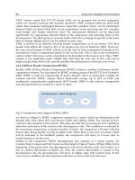
Adaptive antennas can be described as systems usually based on three main parts: the
antenna array, the receiver architecture and the beamforming scheme. Thus, adaptive
antennas have those advantages owing to those three main parts. The system capabilities
increase as complexity and development cost do. Furthermore, since signal processing is the
basement of the adaptive antenna concept it is important to analyze the design challenges in
terms of hardware architecture and components such as processors and embedded systems.
The antenna array provides the capability of performing the antenna pattern meeting the
environment requirement under study. Besides, receiver architectures have some interesting
advantages depending on the implemented receiver arraying technique such as signal to
noise ratio (SNR) and bit error rate (BER) performance enhancement. Furthermore, symbol
synchronization and carrier recovery can be used increasing the receiver complexity but
providing higher performances. Finally, beamforming schemes use multiple antennas in
order to maximize the strength of the signals being sent and received while eliminating, or
at least reducing, interference as discussed in Section 4.3.
Adaptive antenna arrays are often called Smart Antennas because they have some key
benefits over traditional antennas, by adjusting traffic patterns, space diversity or using
multiple access techniques. The main four key benefits are: First, enhanced coverage
through range extension by increasing the gain and steering capability of the ground station
antenna; Second, enhanced signal quality through multi-target capability and reduction of
interferences; finally, adaptive antennas improve the data download capacity in the ground
segment of satellite communication by increasing the coverage range (Martínez et al., 2007).
4.1 Design and architecture based on software defined radio
For design there is the well known waterfall life cyclic model (Royce, 1970) that can be used
to manage main aspects of the design of architectures. Thus, some tasks must be fulfilled
subsequently as follow in Fig. 21.a.
Fig. 21.b shows the design schemes resulting of the requirement analysis stage
corresponding software and hardware system specifications. In the depicted scheme, there
are some system components such as the radiating element and RF circuits that are often
designed under iterative prototyping model.
Analysis of
System
requirements
Design
Implementation
and
components
test
Integration
and system
test
system software
and hardware
specification
components, software
design tools and
hardware platform
Implementatio
n of system
components
integrated
Adaptive
Antenna Array
Adaptive Antenna Array
Antenna Array
Receiver
Architecture
Beamforming
Algorithms
Radiating
element
RF Circuits
Connectors
⁞
Symbol
Sync.
Filter Chain
⁞
Beamformer
Signal
combiner.
⁞
a b
Fig. 21. a) Water life cyclic model of the adaptive antenna array design, and b) Simplified
design scheme of adaptive antenna arrays.
New Antenna Array Architectures for Satellite Communications
185
Regarding the hardware implementation, tables presented in (Martínez et al., 2007) show
the hardware resource consumption in the field programmable gate array (FPGA) Virtex-4
for the least mean squared (LMS) beamforming algorithm with full spectrum combining
(FSC) receiver architecture and SIMPLE beamforming algorithm with symbol combining
(SC) receiver architecture. Both scheme designs have an antenna array of 2 elements. The
algorithm based on correlation requires less hardware. The main difference can be
appreciated in the amount of digital signal processing oriented component (DSP48)
resources, typically used for filtering applications (Martínez et al., 2007).
4.2 Receiver architectures based on algorithms type
Several receiver architectures can be implemented, and they are frequently based on the
type of the beamforming algorithm used. When training signals are available in the
transmitted frame, a time-based reference algorithm can be used. However, this solution is
only valid when the earth station is capable of demodulating the received training sequence.
Other algorithms used in deep space communications are based on signal correlation and
they avoid performing the demodulating process. This kind of algorithms are blind
techniques that do not require any additional signal demodulation before applying some
beamforming technique and work better in low SNR conditions than time-based algorithms.
Several receiver architectures can be implemented exploiting the processing capabilities of
the SDR, such as FPGA, application-specific integrated circuits (ASICS), and digital signal
processing (DSPs). The design of the receiver architecture fundamentally depends on the
selection of beamforming algorithms. An example of beamforming technique is the LMS
algorithm whose estimation of coefficients or weights requires a temporal reference and is
implemented through SC receiver architecture (Fig. 22.a). In the other hand, the SIMPLE
algorithm (Rogstad, 1997) constitutes a beamforming technique that is implemented using
FSC receiver architecture (Fig. 22.b) in order to perform the calculation of weights.
Beam forming
algorithm
C
O
M
B
I
N
E
R
w
1
w
3
w
2
w
4
RF/IF
10.7 MHZ137. 1 MHZ
ADC
RF/IF
10.7 MHZ137. 1 MHZ
ADC
RF/IF
10.7 MHZ137. 1 MHZ
Receiver S o ftware Define d Rad io
ADC
RF/IF
10.7 MHZ137. 1 MHZ
ADC
µ-strip RF circuit
Receiver So ftware Defined Radio
Receiver So ftware Defined Rad io
Receiver So ftware Defined Radio
Beam forming
algorithm
C
O
M
B
I
N
E
R
C
O
M
B
I
N
E
R
w
1
w
1
w
3
w
3
w
2
w
2
w
4
w
4
RF/IF
10.7 MHZ137. 1 MHZ
ADC
RF/IF
10.7 MHZ137. 1 MHZ
ADC
RF/IF
10.7 MHZ137. 1 MHZ
Receiver S o ftware Define d Rad io
ADC
RF/IF
10.7 MHZ137. 1 MHZ
ADC
µ-strip RF circuit
Receiver So ftware Defined Radio
Receiver So ftware Defined Rad io
Receiver So ftware Defined Radio
C
O
M
B
I
N
E
R
RF/IF
10.7 137. 1
A
DC
RF/IF
10.7 137. 1
A
DC
RF/IF
10.7 MHZ 137. 1 MHZ
A
DC
RF/IF
10.7 MHZ 137. 1 MHZ
A
DC
Receiver SDR
A
PT
RECEIVER
DD
C
I
R=12
N
=
CI
R
=
12
N
=
CI
R
=
12
N
=
C
I
R=12
N=
C
O
M
B
I
N
E
R
RF Circuit
DDS
CIC
R=128
N=2
CIC
R=128
N=2
CIC
R=128
N=2
CIC
R=128
N=2
VHDL C++/
VHDL
DSP
CLOC
DUC
VHDL
a b
Fig. 22. Comparison of receiver architectures. a) Symbol Combining (SC), and b) Full
Spectrum Combining (FSC).
The SC architecture can be divided into two more sub-classes which work on a phase-
recovery basis. The complex symbol combining (CSC) recovers the phase information with
regard to a reference element using feed-forward and feedback algorithms. One of the
advantages of this scheme is that the rate of data sent to the combining module has a rate
slightly higher than the symbol rate. For most applications, the symbol rate is relatively low
and is a multiple of the data rate. In this kind of schemes, there is an important cost
Advances in Satellite Communications
186
consideration in real-time applications and the requirements of instrumental phase stability
are very severe (Rogstad et al., 2003). Other type of SC architecture is the stream symbol
combining (SSC). In this kind of scheme, data are sent to the combining module at a rate
equal to the symbol rate. The symbol rate depends on the coding scheme and for most
applications is relatively modest. Also, the requirements of instrumental phase stability are
no severe, as in the case of CSC scheme. The disadvantage of the SSC is the additional
hardware required for each antenna.
Furthermore, there are the baseband combining (BC) and carrier arraying (CA) architectures
discussed in (Rogstad et al., 2003). In BC architectures the signal from each antenna is carrier
locked and combining in baseband for further demodulation and synchronization. In effect,
the carrier signal from the spacecraft is used as a phase reference so that locking to the
carrier eliminates the radio-frequency phase differences between antennas imposed by the
propagation medium. Besides, in CA architectures, one individual carrier-tracking loop is
implemented on each array element. Then, the elements branches are coupled in order to
increase the carrier-to-noise ratio (CNR), but losses of radio channel are far compensated
(Rogstad et al., 2003).
In general, the selection of the beamforming algorithms is determined by the following
aspects: Hardware and computational resources; Speed of convergence and residual error of
adaptive algorithms; Calibration requirements and auto-compensation ability; and system
signal-transmission characteristics.
4.3 Beamforming techniques for satellite tracking
Some satellites transmit useful information inside its frames for synchronization and
tracking purposes. The gathering of satellite data requires the tracking operation along its
earth orbit. To accomplish this goal with adaptive array architectures, some beamforming
techniques should be implemented. Fig. 23 illustrates a simple example of a narrowband
linear adaptive beamformer system.
Adaptive
algorithm
w1
w2
w3
w4
Σ
Σ
-
y(t)
+
d(t)
e(t)
Antenna 1
Antenna2
Antenna3
Antenna4
Beamforming
signal
Desired direction
(main beam)
Undesired
direction (null)
Fig. 23. Adaptive antenna system.
A linear beamformer combines signals according to some weights w
i
, to produce a desired
radiation pattern. The mathematical expression of a linear beamformer at the array output
in vector notation can be expressed as
H
y
wx= , where x is the received signal vector to be
combined,
w are the weights computed by the beamforming algorithm and
H
denotes
transposition and conjugate of
()⋅ .
New Antenna Array Architectures for Satellite Communications
187
In adaptive antennas design, weights are dynamically calculated with a certain algorithm in
order to optimize some signal parameter like signal to interference-plus-noise ratio (SINR),
SNR, or BER. An extended variety of algorithms exist in the literature for beamforming
purpose and the most appropriated selection is done depending on the signal characteristics
of the received signal.
4.3.1 Blind techniques
Blind beamformers make use of an inherent property of the received signal, such as the
ciclo-stationarity of the constant modulus. In the latter, the algorithm eliminates the
fluctuation of the signal amplitude and computes the weights to minimize the effect
produced by those variations. The algorithms that make use of these methods are denoted
as Constant Modulus Algorithms (CMA) (Biedka, 2001).
CMA algorithms present an important disadvantage: as the phase information is not
considered, the constellation of quadrature phase shift keying (QPSK) signals commonly
used in satellite communications appears rotated after beamforming, which imposes the
need of an additional phase recovery subsystem in the array output.
4.3.2 Temporal-reference algorithms
Algorithms based on a temporal reference require a known reference included in the frame
of the signal, such as training sequences, unique word (UW) or pilot bits. Thus, these
schemes are normally used for digital signals. The aim of these beamformers is the
minimization of the energy of an error signal integrated by interferences and noise. In order
to reduce the order of the problem, the weight calculation is usually done iteratively.
The most popular adaptive filters are the LMS and Recursive Least Squares (RLS)
algorithms (Haykin, 2002). Briefly, the main differences lie in the method to calculate and
the final convergence behavior: while LMS has a linear complexity order with the number of
antennas in the array, RLS makes use of matrix operation, so that the complexity order is
quadratic, but the convergence is faster.
An interesting alternative to the LMS is the Normalized LMS (NLMS), which normalizes the
adaptive step to avoid variation during the convergence process. The counterpart is the
more intensive processing requirements to calculate signal power and normalization
operation.
4.3.3 Correlation-based algorithm
In contrast to beamformers based on temporal reference, schemes based on signal
correlation do not require the demodulation of any signal. These techniques are the most
popular to extract the spatial information for beamforming, and we have focused on the use
of the SIMPLE algorithm (Rogstad, 1997). This algorithm has been used by the Deep Space
Network (DSN) of National Aeronautics and Space Administration (NASA) to combine the
signals received from spatial probes in radio telescopes located in different sites around the
Earth surface. The main disadvantage of correlation based schemes is the lack of ability to
cancel interference signals.
4.4 Performance comparison
Some simulation comparisons between spatial and blind algorithms are presented to show
benefits and drawbacks. Four algorithms have been selected with a 4-element uniform linear
Advances in Satellite Communications
188
array (ULA). The spatial algorithms simulated are post-beamformer interference canceller –
orthogonal interference beamformer (PIC-OIB) (Godara, 2004) and minimum power
distortionless response (MPDR) (Van Trees, 2002). On the other hand, the blind algorithms
are the matrix-free EIGEN and the SUMPLE (Rogstad, 1997). The convergence process is
compared as a function of the input SNR as depicted in Fig. 24.
As it can be observed from the above results, spatial algorithms outperform blind ones at
low SNR, and vice versa. On the other hand, with medium-low SNR and low or absence of
interferences, the behavior of all algorithms is quite similar.
a b
Fig. 24. Convergence behavior of spatial versus blind algorithms in the absence of
interferences with several input SNR. a) SNR = 5 dB, and b) SNR = -10 dB.
5. Experimental Test-Bed based on SDR platform
This section presents a test platform known as Adaptive Antenna Array Test-Bed - A3TB,
where a comparative study of several beamforming algorithms can be performed and
modularity of the architecture is a well proved advantage. The test bed is based on SDR
technology and uses a novel architecture that can be used with both blind and spatial-based
beamforming algorithms. The A3TB concept can be applied to a number of scenarios as the
current version is independent of the signal properties. Simulation results using the A3TB
with the APT channel from NOAA satellites show the performance of the concept and the
feasibility of the proposed implementation.
The scope of the system development was is to prove the concept of antenna arrays applied
to ground stations instead of reflectors for different applications, such as telemetry data
downloading or end-user in mobile applications as discussed in the introduction section. In
contrast to reflector antennas, antenna arrays offer the possibility of electronic beam-steering
avoiding the use of complex mechanical parts and therefore reducing the cost of the
antenna. It is also a good chance for Universities and Research Centers aiming to have their
own ground station sited in their installations.
5.1 A3TB concept
The A3TB can be defined as
a software-defined radio beamformer applied to a ground station for
tracking LEO satellites
. The novelty relies on the use of an antenna array to smartly combine
New Antenna Array Architectures for Satellite Communications
189
the received signals from the satellite and its implementation based on SDR technology. The
reason to use an antenna array instead of a single antenna is to electronically steer the beam
in the direction of the satellite along its orbit without requiring a mechanical system for
tracking. In addition to the advantages of the use of SDR technology and antenna array, it is
the modularity and flexible architecture implemented in the A3TB. Fig. 25 shows the A3TB
architecture where it is evident the feasibility to update or change during operation any of
the main blocks. It is possible to change during operation the beamforming algorithm and to
include new beamforming modules to the system. Furthermore, changes on the BENADC
are possible to implement not during operation, but new receiver architecture at off-line
such as those options discussed at follow.
In (Salas et al., 2007), the block diagram represents the software system implementation of
the first version of the test-bed prototype and most of it is based on VHDL. Depending on
the firmware, three options could be installed into the FPGA Virtex4. The option A is
implemented with the signal processing on the PC, so the SIMPLE beamforming is done in
the module developed in C++. The option B is implemented completely on VHDL and this
option need to export the beamforming weights just to draw the array pattern diagram.
Finally, in contrast to the option B, the option C is implemented for the LMS beamforming
algorithm.
With the first version of the Test-Bed, the modularity on the selection of firmwares was
proved switching between A, B or C receiver architectures, and an important result of the
Test-Bed development is the hardware resources occupation presented in (Salas et al., 2007).
The advantage of the SDR implementation is that A3TB architecture can be used to process
any received signal from a LEO satellite in the appropriate band imposed by the RF stages.
Moreover, most of the processing tasks are performed on software, using appropriate
routines to process any receive signal. There are 2 main schemes to implement the
beamforming stage: SC and FSC [41]. Both schemes are compared in Section 4.2.
The current version of the A3TB in Fig. 25.a was updated to track NOAA satellites in the
VHF band, in particular the APT channel. Previous versions of A3TB dealt with LRPT
signals from MetOp-A, where a complete receiver with beamforming and synchronization
stages has been implemented(Salas et al., 2007; Martínes et al., 2007).
5.2 Implementation of the A3TB
The A3TB prototype consists of 4 main parts as shown in Fig. 25.a. The first part is the
antenna array, which has 4 crossed-dipole antennas as depicted in Fig. 25.b. The second part
consists of RF-IF circuits which amplify and down convert to IF incoming signals.
Furthermore, an automatic gain control (AGC) was implemented using two steps of variable
attenuators in the IF domain.
The third part is the SDR platform which consists of the beamforming algorithms
implemented on C++ and the FPGA firmware on VHDL, PC and BENADC blocks show in
Fig. 25, respectively. The hardware resources occupation for this Test-Bed implementation is
similar to one presented in (Martínes et al., 2007). The last part is the software from weather
satellite signal to image decoder (WXtoImg) on the PC using the sound card output/input
in order to get the weather satellite image.
Since the implemented architecture is FSC the demodulation is not required and the IF
signal is digitized. For the signal processing hardware design the BenADC-v4 has been
chosen. This solution includes a FPGA Xilinx Virtex4-SX55 with four 12-bit analog inputs at
Advances in Satellite Communications
190
a b
Fig. 25. a) Block diagram of the A3TB, and b) BenADC – Virtex 4-sx55.
250 Msps (Martínes et al., 2007). Digital samples are transferred to the PC where
beamforming and subsequent APT demodulation of the array output are performed using
C++ routines. This implementation design offers higher flexibility for testing different
beamforming schemes. Finally, demodulated APR frames are sent to the WXtoImg software
to show meteorological maps.
The A3TB is controlled by the PC for simulations and field trials. The graphical user
interface allows presented in (Salas et al., 2008) the user to choose the beamforming
algorithm and set all the parameters of the LEO satellite for tracking such as the number of
antennas of the array, distance between the elements, direction of arrival and IF frequency.
The C++ routine calculates the beamforming weights and plots the synthesized array factor.
Subsequently, the reception of meteorological images has real time system requirements.
Thus, it is necessary a data transfer from the FPGA to the C++ module to process the
samples continuously, and give APT frames to the audio output of the PC. Since, the
meteorological satellites often have a low baud rate, in the case of study with NOAA
satellites the data transfer is made using two buffers controlled by a thread.
It is important to mention that the A3TB with SDR architecture can evaluate different
beamforming algorithms and receiver schemes. The update of A3TB for larger arrays is
immediate, as the basis for algorithms is independent of the number of elements in the
array. The architecture of a new ground station concept to track LEO satellites based on
software defined radio and antenna arraying as Test-Bed is a well proved choice to evaluate
future antenna array architectures for satellite communication and benchmark features of
the proposed system. As the A3TB VHF version is based on FSC scheme, the concept can be
applied to a number of satellite tracing scenarios.
6. Conclusions
The performance analysis of different beamforming algorithms is an important issue in the
new generation antenna array development and research. Thus, A3TB helps to analyze
beamforming algorithms paving the way for testing and debugging for posteriori use in
larger arrays, such as GEODA. Results obtained in real scenarios with A3TB state, for
example, that spatial reference algorithms such as MPDR should be used in the absence of
interferences, whereas blind algorithms are appropriate for low SNR conditions. Finally, the
A3TB can also serve to validate the performance of calibration procedures.
New Antenna Array Architectures for Satellite Communications
191
In future work, the A3TB will deal with the system combining of full modularity with the
capability of change firmwares based on the first version design of the Test-Bed, plus the
flexible architecture of the current design of the Test-Bed based on VHDL, C++ and Antenna
Arraying. Furthermore, the addition of more modules to increase the number of antenna
array elements is evident in next generations.
7. Acknowledgment
Authors wish to thank MICINN (Ministerio de Ciencia e Innovación) for grants and
CROCANTE project (ref: TEC2008-06736/TEC), INSA (Ingeniería y servicios
Aeroespaciales) and Antenas Moyano S.L., for the partial funding of this work. Simulations
in this work have been done using CST Studio Suite 2011 under a cooperation agreement
between Computer Simulation Technology and Universidad Politécnica de Madrid.
Substrates used in prototypes were kindly given by NELCO S.A.
8. References
Torre, A.; Gonzalo, J.; Pulido, M., & Martínez Rodríguez-Osorio, R. (2006). New generation
Ground Segment Architecture for LEO satellites.
57th International Astronautical
Congress
, pp. 221-226. Valencia, Spain, October 2006.
Tomasic, B.; Turtle, J. & Liu, S. (2002). A Geodesic Sphere Phased Array Antenna for satellite
control and communication.
XXVII General Assembly of the International Union of
Radio Science,
Maastricht, August 2002.
Godara, L. C. (1997). Application of Antenna Arrays to Mobile Communication, Part II:
Beamforming and Direction of Arrival Considerations.
Proc. IEEE , vol.85, No.8,
(August 1997), pp. 1195-1245.
Martínez, R. & Salas Natera, M. A. (2010). On the use of Ground Antenna Arrays for Satellite
Tracking: Architecture, Beamforming, Calibration and Measurements.
61st
International Astronautical Congress
, pp. 1-7. Prague, 2010.
Liu, S.; Tomasic, B.; Hwang, S. & Turtle, J. (2006). The Geodesic Dome Phased Array
Antenna (GDPAA) for Satellite Operations Support.
IEEE 18th International
Conference on Applied Electromagnetics and Communications
, pp. 1-1, Dubrovnik, April
2006.
Tomasic, B. (1998). Analysis and Design Trade-Offs of Candidate Phased Array
Architectures for AFSCN Application.
Second AFSCN Phased Array Antenna
Workshop,
Hanscom, April 1998.
Sierra Pérez, M.; Torre, A.; Masa Campos, J. L.; Ktorza, D. & Montesinos, I. (2007). GEODA:
Adaptive Antenna Array for Metop Satellite Signal Reception.
4th ESA International
Workshop on Tracking, Telemetry and Command System for Space Application
, pp. 1-4,
Darmstadt, Germany, September 2007.
Arias Campo, M.; Montesinos Ortego, I.; Fernández Jambrina, J. & Sierra Pérez, M. (2010).
T/R Module Design for GEODA Antenna.
4th European Conference on Antenna and
Propagation,
pp. 115-116, Barcelona, Spain, April 2010.
Advances in Satellite Communications
192
Franchi, A.; Howell, A. & Sengupta, J. (2000). Broadband mobile via satellite: Inmarsat
BGAN. IEEE Seminar on the Critical Success Factors - Technology, Services and Markets,
pp. 23-30, October 2000.
Evans, J. V. (1998). Satellite systems for personal communications.
Proc. IEEE , Vol.86, No.7,
(July 1998), pp. 1325-1341.
Wu, W. W. (1994). Mobile satellite communications.
Proc. IEEE , Vol.82, No.9, (September
1994), pp. 1431-1448.
Fujimoto, K. & James, J. (2001).
Mobile Antenna Systems Handbook. Artech House.
Garcia Aguilar, A.; Inclán Alonso, J. M.; Vigil Herrero, L.; Fernández González, J. M. &
Sierra Pérez, M. (2010). Printed antenna for satellite communications.
IEEE
International Symposium on Phased Array Systems and Technology
, pp. 529-535, Boston,
USA, October 2010.
Geissler, M.; Woetzel, F.; Bottcher, M.; Korthoff, S.; Lauer, A. & Eube, M., (2010). L-band
phased array for maritime satcom.
IEEE International Symposium on Phased Array
Systems and Technology
, pp. 518-523, Boston, USA, October 2010.
Baggen, R.; Vaccaro, S. & Del Río, D. (2007). Design Considerations for Compact Mobile Ku-
Band Satellite Terminals.
EuCAP The Second European Conference on Antennas and
Propagation
, pp. 1-5. Edimburg, Scothland, September 2007.
Vaccaro, S.; Tiezzi, F.; Rúa, M. & De Oro, C. (2010). Ku-Band Low-Profile Rx-only and Tx-Rx
antennas for Mobile Satellite Communications.
IEEE International Symposium on
Phased Array Systems and Technology
, pp. 536-542, Boston, USA, October 2010.
Schippers, H. (2008). Broadband Conformal Phased Array with Optical Beam Forming for
Airborne Satellite Communication.
IEEE Aerospace Conference, pp. 1-17, September
2008.
Kanno, M.; Hashimura, T. T.; Sato, M.; Fukutani, K. & Suzuki, A. (1996). Digital beam
forming for conformal active array antenna.
IEEE International Symposium on Phased
Array Systems and Technology
, pp. 37-40, October 1996.
Khalifa, I. & Vaughan, R. (2007). Optimal Configuration of Multi-Faceted Phased Arrays for
Wide Angle Coverage.
IEEE 65th Vehicular Technology Conference, pp. 304-308,
Boltimore, USA, April 2007.
Salas Natera, M. A.; Martínez Rodríguez-Osorio, R.; Antón Sánchez, A.; García-Rojo, I. &
Cuellar, L. (2008). A3TB: Adaptive Antenna Array test-bed for tracking LEO
satellites based on software defined radio.
59th International Astronautical Congress,
pp. 313-317, Glasgow. September 2008.
Salas Natera, M. A.; Martínez Rodríguez-Osorio, R. & García-Rojo López, I. (2007). Design of
an Adaptive Antenna Array Test-Bed based on Software Radio for Tracking LEO
Satellites.
IEEE EuCAP. Edinburgh, Scotchland, Npvember 2007.
Martínez, R.; Salas Natera, M.; Bravo, A.; García-Rojo, I.; de Haro, L.; Mateo, M. & Gómez,
M. (2007). VHF Ground Station with increased angular coverage for reception of
meteorological satellites with electronic beamforming.
4th ESA International
Workshop on Tracking, Telemetry and Command Systems for Space Application.
Darmstadt, Germany, 2007.
Mailloux, R. (2005).
Phased Array Antenna Handbook, Artech House, Norwood,
Massachusetts, USA.
New Antenna Array Architectures for Satellite Communications
193
Josefsson, L. & Persson, P. (2006). Conformal Array Antenna. Theory and Design, John Wiley &
Sons , Hoboken, New Jersey, USA.
Montesinos, I.; Sierra Pérez, M.; Fernández, J. L.; Martínez, R. & Masa, J. L. (2009). GEODA:
Adaptive Antenna of Multiple Planar Arrays for Satellite Communications.
European Conference on Antenna and Propagation. Berlin, Germany, 2009.
Salas Natera, M. A.; Martínez, R.; De Haro Ariet, L. & Fernández Jambrina, J. (2010).
Automated System for Measurement and Characterization of Planar Active Arrays.
IEEE Internationa Symposium on Phase Array Systems and Technology, pp. 1-6, Boston
USA, October 2010.
Sierra-Castañer, M.; Vera-Isasa, M.; Sierra-Pérez, M. & Fernández-Jambrina, J. (2005).
Double-Beam Parallel Plate Slot Antenna.
IEEE Transactions on Antennas and
Propagation
, vol.53, No.3, (2005) pp. 977-984.
Garg, R.; Bhartia, P.; Bahl, I. & Ittipiboon, A. (2001). Microstrip Antennas Design Handbook,
Artech House, Norwood, Massachusetts, USA.
Tang, C. & Chen, M. (2007). Synthesizing Microstrip Branch-Line Couplers With
Predetermined Compact Size and Bandwidth.
IEEE Transactions on Microwave
Theory and Techniques, vol. 55, No.9,
(September 2007), pp. 1926-1934.
Bialkowski, M.; Jellett, S. & Varnes, R. (1996). Electronically Steered Antenna System for the
Australian Mobilesat.
IEEE Transaction on Antennas ans Propagation, vol. 143, No. 4,
(August 1996), pp. 347-352.
Alonso, J.; Blas, J.; Garcia, L.; Ramos, J.; Pablos, J. & Grajal, J. (1996). Low Cost Electronically
Steered Antenna and Receiver System for Mobile Saltellite Communications.
Trans.
IEEE MTT
, vol. 44, No. 12, (December 1996), pp. 2438-2449.
Fernández, J. M.; Rizzo, C. & Sierra-Pérez, M. (2009). Antena Impresa Multihaz con
Polarización Circular Derechas/Izquierdas Para Comunicaciones por Satélite en
Banda X.
Proccedings of XXIV Simposium Nacional de la Unión Científica Internacional
de Radio (URSI).
Santander, Spain, September 2009.
Encinar, J. A. & Zornoza, J. (2003). Broadband design of three- layer printed reflectarrays.
IEEE Transactions on Antennas and Propagation, vol. 51, No. 7, (July 2003), pp. 1662-
1664.
Padilla, P.; Muñoz-Acevedo, A.; Sierra-Castañer, M. & Sierra-Pérez, M. (2010). Electronically
reconfigurable transmitarray at Ku band for microwave applications.
IEEE
Transactions on Antennas and Propagation
, vol. 58, No. 8, (August 2010), pp. 2571-
2579.
Padilla, P.; Muñoz-Acevedo, A. & Sierra-Castañer, M. (2010). Low Loss 360º Ku Band
electronically Reconfigurable Phase Shifter.
International Journal of Electronics and
Communications,
vol. 64, No. 11, (November 2010), pp. 1100-1104.
Royce, W. W. (1970). Managing the Development of Large Software Systems. IEEE
WESCON
, pp. 328 – 338, 1970.
Rogstad, D. H. (1997).
The SUMPLE Algorithm for Aligning Arrays of Receiving Radio Antennas:
Coherence Achivied with Less Hardware and Lower Combining Loss.
TDA Progress
Report, Jet Propulsion Laboratory.
Advances in Satellite Communications
194
Rogstad, D. H.; Mileant, A. & Pham, T. (2003). Antenna Arraying Techniques in the Deep Space
Network.
Deep Space Communication and Navegation Series, JPL California
Institute of Technology, Ref. 03-001, Pasadena, USA.
Biedka, T. E. (2001).
Analysis and Development of Blind Adaptive Beamforming Algorithms.
PdD Thesis, Faculty of Virginia Polytechnique Institute and State University,
Virginia.
Haykin, S. (2002).
Adaptive Filter Theory (4th ed.). Prentice-Hall.
Godara, L. C. (2004).
Smart Antennas (1st ed.). CRC Press
Van Trees, H. L. (2002).
Optimum Array Processing. Part IV of Detection, Estimation, and
Modulation Theory
. Wiley.