Behaviour of Electromagnetic Waves in Different Media and Structures Part 5 pdf
Bạn đang xem bản rút gọn của tài liệu. Xem và tải ngay bản đầy đủ của tài liệu tại đây (18.02 MB, 30 trang )
Behaviour of Electromagnetic Waves in Different Media and Structures
108
To avoid the influence of air-gap to the testing result, a rock sample holder is make as
shown in fig. 3.
The practical testing equipment including a VNA is shown in Fig. 4.
In equation (17) and (18), because the Bessel function has oscillating property, the main
difficulty focuses on the Bessel function with integral variable. Obviously these nonlinear
equations have no analytical solution. So we uses numerical solution here. A big number
(12500) is used for the positive infinite of the upper limit during the numerical intergal. The
value of the big number is determined by different testing of many conditions.
2.3 Calibration
The calibration in this measurement includes two steps, one is the transmission line
calibration, and the other is the probe calibration.
2.3.1 Transmission line calibration
The VNA is a exact device and is connected to coaxial probe through a coaxial cable.
According to the operation requirement of the network analyzer, the coaxial line is
calibrated using calibrating kits. The detailed operation process as follows.
1.
VNA parameters setting. The frequency range is between 1MHz-1GHz in this test
according to our request. Power can be selected by our need, for example, 0dBm. Large
power is believed to sense large sample volume. We choose 1000 sampling points here.
2.
Calibration process. We use single port calibration here because we only measure S11.
The calibration kits which including the device SHORT, LOAD, and OPEN are used to
calibrate the VNA. After this process, the reference plane for VNA is at the end of the
coaxial cable. However, because the reflection surface is on the flange surface, not the
end of the cable, further calibration is still needed.
2.3.2 Probe calibration
Probe calibration is an indirect method. We use short-circuit, the air, and the de-ionized
water to calibrate the probe.
If
m
Γ is the reflection coefficient obtained through measuring and
a
Γ is the practical
reflection coefficient of probe terminal,
m
Γ can be expressed as (Blackham & Pollard, 1997):
ra
md
sa
e
e
1-e
Γ
Γ= +
Γ
(19)
where,
d
e is the limited directivity error;
r
e is frequency response error;
s
e is equivalent
source matching error. The reflection coefficient of the material
a
Γ can be calculated
through equation (17) or (18). Through measuring the reflection coefficient of three kinds of
materials
m
Γ , the three equations about
d
e ,
r
e ,
s
e can be obtained. There are three variables
and three equations, the error coefficients
d
e ,
r
e ,
s
e can be obtained.
Short-circuit, and air are ideal calibration materials. The third material must have known
permittivity. The de-ionized water is selected as the third calibration material here. When it
is of short-circuit,
a
-1Γ= ; when the calibration material is air, the reflection coefficient of
every frequency can be calculated through equation (17) or (18), because the permittivity of
air is 1. According to the same theory, the reflection coefficient of de-ionized water can be
calculated. Here, the reflection coefficient of water is obtained through the Cole-Cole
formula.
Wide-band Rock and Ore Samples Complex Permittivity Measurement
109
()
s
1-
0
-
-j
1j/
∞
∞
α
εε
′′′
ε=ε ε =ε +
+ωω
(20)
where,
s
ε is a direct current permittivity.
∞
ε is an optical frequency permittivity.
0
ω is a
Debye relaxation angle frequency.
α is a Cole-Cole factor.
By substituting the reflection coefficient of air film
air _ a
Γ and
air _ m
Γ , the reflection coefficient
of de-ionized water
water _ a
Γ and
water _ m
Γ and the reflection coefficient of short-circuit
short _ a
-1Γ= and
short _ m
Γ into the equation (19) separately. We get,
air _ a water _ a air _ a
s
water_a air_a water_a water_a air_a
CC-
e
CC -
Γ+Γ +Γ
=
ΓΓ+Γ +Γ Γ
(21)
where,
water _ m
-A
C
A-B
Γ
=
,
air _ m
A =Γ ,
short _ m
B =Γ .
We can also get,
water _ m
r
water _ a air _ a
s water_a s air_a
-A
e
-
1-e 1-e
Γ
=
ΓΓ
ΓΓ
(22)
rair_a
d
sair_a
e
eA-
1-e
Γ
=
Γ
(23)
It can be concluded based on the equation (19) that:
()
md
a
sm d r
-e
e-ee
Γ
Γ=
Γ+
(24)
Equation (24) determines the second step calibration. Fig. 7 shows the comparison among
results before and after calibration for PTFE and de-ionized water, separately.
Fig. 5. Reflection coefficient before and after calibration
It can be seen that the real part of PTFE measured can be calibrated to around but different
from 1.
Behaviour of Electromagnetic Waves in Different Media and Structures
110
2.4 Inversion calculation and error evaluation
If the permittivity of a material measured is known, the interface reflection coefficient (or
admittance) can be calculated. This process is a forward one. The reverse process can be
solved numerically. The following equation can be obtained from equation (18),
()
()
()
()()
2
0c 0c
bc
cc
0
bc c
Jka-Jkb
1- k
1-
1
YYk dk
1 ln(b / a) 1 k k
∞
η
Γ
Γ
== ⋅
+Γ +Γ
(25)
The solution is:
1-Y
1Y
Γ=
+
(26)
Because it is a complex calculation, the objective function is defined as
() ( ) ()
22
mc mc
faRe- Im-ε= Γ Γ + Γ Γ
(27)
α is a weighting coefficient in this equation,
m
Γ and
c
Γ are measured and the calculated
reflection coefficients. The real part and the imaginary part should be treated equally to
avoid that the large part dominates over the small part too much. This is the typical
optimization problem. Here, ε can be thought as a complex-single variable. But the most
mathematical software optimization tool can not process complex variable optimization
question. So the complex permittivity is divided to real part and imaginary part. The
variable x is a vector array, where,
()
1
xRe=ε,
()
2
xIm=ε. The selection of weighting
coefficient is based on the numerous tests.
We solve the optimization process using the simplex method. The value of
()
f ε after the
optimization for every frequency is displayed in Fig. 6 for the material PTFE. It can be seen
that the precision is very well. When the optimization stops, the objective function of
minimum point satisfy the error requirement.
Fig. 6. The value of optimization objective function
We testify this technique using a standard material PTFE, air, and methanol.
Wide-band Rock and Ore Samples Complex Permittivity Measurement
111
We first test this technique with PTFE whose thickness is 10.50mm in this paper and has
permittivity of 2.1-j0.0004 (Li & Chen, 1995) in microwave band. Because the imaginary part
can not be measured exactly for lowly lossy medium (Wu et al., 2001) by this technique, we
ignore the analysis for the imaginary part. The inverted permittivity is displayed in Fig. 7.
The real part relative error at every frequency is displayed in Fg. 8.
Fig. 7. Permittivity of PTFE sample
Fig. 8. Real part relative error of the permittivity of PTFE sample
We noticed that the arisen relative error is within 5% basically. The average relative error is
1.2749%. One of the many reasons leading to the error is the air gap between the flange and
the sample. The main reasons of producing air gap are that the upper surface and down
surface are not parallel and clean enough, and the upper surface and the down surface do
not touch enough with coaxial probe flange-plane and short-circuit board, although we
already tried our best.
The permittivity calculated by the air film is displayed in Fig. 9.
Behaviour of Electromagnetic Waves in Different Media and Structures
112
Fig. 9. Permittivity of the air
The relative error is 0.7692%. Because the air is a kind of calibration material, the
permittivity of air calculated should be theoretical value 1.The relative error is below 0.8%.
It proves the validity of inversion process.
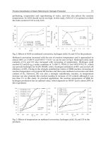
The measured permittivity for methanol is displayed in Fig. 10.
Fig. 10. Permittivity of methanol
The measured permittivity for methanol is compared with the theoritical values which is
calculated by the debye equation or cole-cole equation (Jordan et al., 1978) as shown in Fig.
10. The measured data is accetable except that they have clear difference with the theotitical
ones at high frequency range. The reducement of this error could be the future topic.
3. Measured results and analysis
342 rocks and ores sample within 31 categories from 6 mines are measured and analyzed in
this part by using open-coaxial probe technique. The photos for these rocks and ores
samples are shown in Fig. 11.
Wide-band Rock and Ore Samples Complex Permittivity Measurement
113
Fig. 11. Photographs of the rocks and ores samples from 6 metal mines
3.1 Samples from the Changren nickel-copper mine, Jilin, China
Table 1 shows the messages of rocks and ores from the Changren nickel-copper mine, Jilin,
China.
Fig.12 shows marbles permittivities as an example, the solid and the dashed lines denote the
real parts and the imagery parts. We find the values are diverse for the same rock. We think
this kind of diversity is due to the fact of that the probe senses a small range and the
samples are in-homogeneous. Therefore, we use the averaging value of these data to
represent this sample, because the averaging could reflect the total characteristic.
Fig. 13 shows the average permittivities of all rocks and ores from the Changren nickel-
cooper mine, China. We find high grade ore and medium grade ore have highest values,
then the values range from high to low are the pyroxene peridotite, low grade ore, light
alterative bornblende pyroxenite, marble, hybrid diorite, granitization granite.
Behaviour of Electromagnetic Waves in Different Media and Structures
114
Rocks Rock or Ore names Fig. no. Measured permittivity Sample number
1 granite 11(1a) 5-7.5 25
2 marble 11(1b) 5-10 8
3 hybrid diorite 11(1c) 5-10 16
4 altered hornblende pyroxenite 11(1d) 5-17 7
5 pyroxene peridotite 11(1f) 10-20 10
ores:
6 low-grade ore 11(1g) 9-23 9
7 medium-grade ore 11(1f) 20-70 10
8 high-grade ore 11(1h) 5-95 12
Table 1. Rocks and ores from the Changren nickel-copper mine, Jilin, China
Fig. 12. Permittivity of marbles. (a) 8 Marble’s samples permittivities; (a) average of mable
samples’ permittivities
Fig. 13. Averaged relative permittivities of rocks and ores from the Changren nickel-cooper
mine
Wide-band Rock and Ore Samples Complex Permittivity Measurement
115
Actually, the pyroxene peridotite, light alterative bornblende pyroxenite are basic rocks and
ultra-basic rock which were ore carrier. When ore’s grade is low, the permittivity represents
the carrier rock’s property. These basic rocks and ultra-basic rock come from tectonic
emplacement. The granitized granite is the host rock which has distinguished lower values.
These measured data show optimistic aspect for borehole radar detection for metal ore-body.
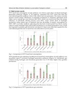
3.2 The samples from the Huanghuagou lead-zinc mine, Chifeng, Inner Mongolian,
China
The table 2 shows the message of rocks and ores from the Huanghuagou Lead-Zinc mine
Chifeng, China. Ores and rocks ranked by permittivity from high to low are high-grade ore,
pyrite, medium-grade ore, dacitoid crystal tuff, low-grade ore, crystal tuff, tuffaceous
breccia, tuffaceous sandstone, and dacite. The high-grade ore, pyrite, and the medium-grade
ore are distinguishable from each other and the others.
Rocks Rock or Ore names Fig. no permittivity Samples number
1 tuffaceous fine-grained sandstone 11(2a) 5-7 5
2 tuffaceous breccia 11(2b) 5-6 5
3 dacitoid crystal tuff 11(2c) 5.5-8 13
4 dacite 11(2d) 5.5-6 10
5 crystal tuff 11(2e) 5-7.5 11
Ores
6 high-grade ore 11(2f) 10-70 11
7 medium-grade ore 11(2g) 10-12 5
8 low-grade ore 11(2h) 5-10 8
9 pyrite 11(2i) 20-40 4
Table 2. Messages of the Huanghuagou lead-zinc mine, Chifeng, Inner Mongolian, China
Fig. 14. Averaging permittivities of ores and rocks from the Huanghuagou lead-zinc mine,
Chifeng, Inner Mongolian, China
3.3 Samples from the Nianzigou molybdenum mine, Chifeng, Inner Mongolian, China
The table 3 shows the messages of rocks and ores from the Nianzigou molybdenum mine,
Chifeng, Inner Mongolian, China. Ores and rocks ranked by permittivity from high to low
are high-grade ore, low-grade ore, and altered K-feldspar granite. The high-gride ore is
Behaviour of Electromagnetic Waves in Different Media and Structures
116
distinguishable from other two, and the low-grade ore shows the nearly same permittivity
as altered K-feldspar grinate.
Rocks Rock or Ore names Fig. no permittivity Samples number
1 altered K-feldspar granite 11(3a) 4.5-7.5 23 samples
Ores
2 high-grade ore 11(3b) 5-15 7 (No: 02, 05, 07, 08, 09, 10, 11)
3 low-grade ore 11(3c) 4-10 4 (No: 01, 03, 04, 06)
Table 3. Messages of rocks and ores from the Nianzigou molybdenum mine, Chifeng, Inner
Mongolian, China
Fig. 15. Averaging permittivities of the rocks and ores from the Nianzigou molybdenum
mine, Chifeng, Inner Mongolian, China
3.4 Samples from the Qunji copper mine, Xinjiang, China
The table 4 shows the messages of rocks and ores from the Qunji Copper mine, Xinjiang,
China. Ores and rocks ranked by permittivity from high to low are albitophyre ore, quartz
albitophyre, breccia porphyry, malachite copper oxide ore, and albite rhyolite porphyry. The
albitophyre ore is clearly distinguishable from the others in the real part. Other rocks and
ore are ambitious in permittivity.
Rocks Rock or Ore names Fig. no Permittivity Samples number
1 albite rhyolite porphyry (core) 11( 4a) 5-5.5 8
2 breccia porphyry 11(4b) 5-5.5 14
3 quartz albitophyre 11(4c) 5-7.5 11
Ores
4 albitophyre ore 11(4d) 5-10
16(No
:01-09,11-17)
5 malachite oxide ore 11(4e) 5-5.5
14(No.
:01-14)
Table 4. Messages of rocks and ores from the Qunji Copper mine, Xinjiang, China
Wide-band Rock and Ore Samples Complex Permittivity Measurement
117
Fig. 16. Average permittivities of rocks and ores from the Qunji Copper mine, Xinjiang,
China
3.5 Samples from the Musi copper mine, Xinjiang, China
The table 5 shows the messages of rocks and ores from the Musi copper mine, Xinjiang,
China. Ores and rocks ranked by permittivity from high to low are vesicular amygdaloidal
andesite, massive diorite, and andesitic copper ore. The andesitic copper ore is
distinguishable from the others and shows low permittivity characteristic which is opposite
to other mines.
Fig. 17. Averaging permittivities of rocks and ores from the Musi copper mine, Xinjiang,
China
Behaviour of Electromagnetic Waves in Different Media and Structures
118
Rocks Rock or Ore names Fig. no Permittivity Samples number
1 vesicular amygdaloidal andesite 11(5a) 5.5-12.5 19 samples
2 massive diorite 11(5b) 7.5-11 12 samples
Ores Total:24
3 andesitic copper ore 11(5c_1; 5c_2) 5-10 24 samples
Table 5. Messages of rocks and ores from the Musi copper mine, Xinjiang, China
3.6 Samples from the Zengnan copper mine, Xinjiang, China
The table 6 shows the messages of rocks and ores from the Zengnan copper mine, Xinjiang,
China. Ores and rocks ranked by permittivity from high to low are lead-zinc ore, copper ore,
and glutenite. Three of them can be distinguished from each other.
Rocks Rock or Ore names Fig. no Permittivity Samples number
1 glutenite 11( 6a) 8-14 6
Ores
2 copper ore 11(6b) 8-40 11
3 lead-zinc ore 11(6c) 15-45 4
Table 6. Messages of rocks and ores from the Zengnan copper mine, Xinjiang, China
Fig. 18. Averaging permittivities of rocks and ores from the Zengnan copper mine, Xinjiang,
China
4. Conclusion
Open-ended coaxial technique can measure the permittivity in wide frequency range
quickly. The sample machining is relatively simple, and only the smooth surfaces of the
sample sheets are required. Because the sensing range of the probe concentrates mainly at
the center of the probe and the samples measured are no so homogeneous, we use averaging
value from several samples of a rock or ore to reduce the random effect due to their in-
Wide-band Rock and Ore Samples Complex Permittivity Measurement
119
homogeneity. It is shown that permittivity of metal ore is higher than other rocks, and high-
grade ore is distinguishable from surrounding rocks. These measurements provide insights
into the wide-frequency permittivity of metal ores and rocks, and also provide basis for
electromagnetic exploration by borehole radar.
There are still couple of problems with the current research. The sizes of the flange, the
aperture of the probe, sheet sample thickness, are not optimized yet. The sensing area for
the current probe is small for the inhomogeneous rocks and ores. These are all future works
for us.
5. Acknowledgment
This research is supported by the National Natural Science Foundation of China (Grant No
40874073 and 41074076), and by the National High-Tech R&D Program 863 (Grant No
2008AA06Z103)
6. References
Blackham, D.V. & Pollard, R. D. (1952). An improved technique for permittivity
measurements using a coaxial probe.
IEEE Transactions on Instrumentation and
Measurement
, Vol. 46, No. 5, (Sept., 1997), pp.1093-1099, ISSN 0018-9456
Coutanceau-Monteil, N., & Jacquin, C. (1960). Improvements of the coaxial line technique
for measuring complex dielectric permittivity of centimetric samples in the 20 to
1000 MHz range: application to sedimentary rocks.
Log Analyst, Vol. 34, No. 5,
(September-October, 1993), PP. 21-33, ISSN 1529-9074
Daniels, D. (2004).
Ground Penetrating Radar, 2nd Edition, The Institution of Engineering and
Technology, ISBN 0863413609, London, United Kingdom.
Fan S.; Staebellk K. & Misra D. (1952). Static analysis of an open-ended coaxial line
terminated by layered media.
IEEE Transactions on Instrumentation and Measurement,
Vol. 39, No. 2, (March, 1990), pp.435-437, ISSN 0018-9456
Hoshina, S.; Kanai, Y. & Miyakawa, M. (1965). A numerical study on the measurement
region of a coaxial probe used for complex permittivity measurement.
IEEE Trans.
Magn
, Vol. 37, No. 5, (Sept., 2001), pp. 3311-3314, ISSN 0018-9464
Jol, H. M. (2009).
Ground Penetrating Radar Theory and Applications, ELSEVIER, ISBN
0444533486, Amsterdam, the Netherlands.
Jordan, B P ; Sheppard, R J & Szarnowski, S. (1950). The dielectric properties of formamide,
ethanediol and methanol.
J. Phys. D: Appl. Phys, Vol. 11, No. 5, (April, 1978), pp.
695-701, ISSN 0022-3727
Kraszewski, A.W. (1965). Microwave aquametry - A review.
Journal of Microwave Power, Vol.
15, No. 4, (1980), pp. 209-220, ISSN 0022-2739
Li, C. L. & Chen, K. M. (1952). Determination of electromagnetic properties of materials
using flanged open-ended coaxial probe-full-wave analysis.
IEEE Transactions on
Instrumentation and Measurement
, Vol. 44, No.1, (Jan., 1995), pp. 19-27, ISSN 0018-
9456
Misra, D. K. (1963). A quasi-static analysis of open-ended coaxial lines.
IEEE Transactions on
Microwave Theory and Techniques
, Vol. 35, No. 10, (1987), pp. 925-928, ISSN 0018-
9480
Behaviour of Electromagnetic Waves in Different Media and Structures
120
Nelson, S.O & Bartley, P. G. (1952). Open-ended coaxial line permittivity measurements on
pulverized materials.
IEEE Transactions on Instrumentation and Measurement, Vol. 47,
No.1, (Jan., 1998), pp. 133-137, ISSN 0018-9456
Nicolson, A. M. & Ross, G. (1952). Measurement of intrinsic properties of Materials by time
domain techniques.
IEEE Trans on Instrument & Measurement, Vol. IM-19, No. 4,
(November 1970), pp. 377-382, ISSN 0018-9456
Nyshadham, A.; Sibbaldcl, C. L. & Stuchly, S. S. (1963). Permittivity measurements using
open-ended sensors and reference liquid calibration an uncertainty analysis.
IEEE
Transactions on Microwave Theory and Techniques
, Vol. 40, No. 2, (Feb., 1992), pp. 305-
314, ISSN 0018-9480
Roberts, S. R. & Hippel, A. Von. (1930). A new method for measuring dielectric constant and
loss in the range of centimeter wave.
Journal of Applied Physics, Vol. 17, No. 7, (July,
1946), pp. 610-616, ISSN 0021-8979
Shen, L. C. (1961). A laboratory technique for measuring dielectric properties of core
samples at ultrahigh frequencies.
Society of Petroleum Engineers Journal, Vol. 25 No.
4, (April, 1985), pp. 502-514, ISSN 0197-7520
Shi, X. D. & Shen, L. C. (1958). Dielectric properties of reservoir rocks at very-high
frequencies.
ACTA GEOPHYSICA SINICA, Vol. 32, No. 1, (Jan. 1989) pp. 99-110,
ISSN 00015733
Shen, L.C.; Marouni, H.; Zhang, Y.X. & Shi, X.D. (1963). Analysis of the parallel disk sample
holder for dielectric permittivity measurement,
IEEE transaction on geoscience and
remote sensing, Vol. GE-25, No.5, (Sept. 1987), pp. 534-540, ISSN 0196-2892
Stuchly, M. A. & Stuchly S. S. (1952). Coaxial line reflection methods for measuring dielectric
properties of biological substances at radio and microwave frequencie-a review.
IEEE Trans. Instrum. Meas., Vol. 29, No.3, (Sept., 1980), pp.176-183, ISSN 0018-9456
Venkatesh, M. S. & Raghavan, G. S. V. (1949). An overview of dielectric properties
measuring techniques.
CANADIAN BIOSYSTEMS ENGINEERING, Vol. 47, No. 7,
(2005), pp. 15-30, ISSN1492-9058
Weir, W. B.(1913). Automatic Measurement of Complex Dielectric Constant and
Permeability at Microwave Frequency.
Proc. IEEE, Vol. 62, No. 1, (Jan. 1974), pp.33-
36, ISSN 0018-9219
Wei, W. & Sridhar, W. (1963). Radiation-corrected open-ended coax line technique for
dielectric measurements of liquids up to 20 GHz.
IEEE Transactions on Microwave
Theory and Techniques, Vol. 39, No.3, (March, 1991), pp. 526-531, ISSN 0018-9480
Wu, M. Z.; Yao , X. & Zhang, L, Y. (2000). An improved coaxial probe technique for
measuring microwave permittivity of thin dielectric materials.
Measurement Science
and Technology, Vol. 11, No. 11, (2000), pp. 1617-1622, ISSN 0957-0233
Zheng, H. & Smith, C. E. (1991). Permittivity measurement using a short open-ended coaxial
line probe.
IEEE Microw. Guided Wave Lett, Vol. 1, No.11, (November, 1991), pp. 337-
339, ISSN 1051-8207
7
Detection of Delamination in Wall Paintings by
Ground Penetrating Radar
Wanfu Wang
Dunhuang Academy
People's Republic of China
1. Introduction
Wall painting is an important part of cultural heritage. Generally speaking, painting on the
wall of buildings or rocks, and those on the wall of caves are called wall paintings. But
painting on the rock face is called rock painting. Wall painting on the building can be
approximately classified into drawing murals, relief frescoes, mosaic murals and etcetera
material paintings. Chinese ancient wall paintings can be generally distinguished according
to different drawing site, such as palace paintings, temple paintings, grotto frescoes, coffin
chamber murals, residential paintings and so on. Most of the paintings, including grotto
frescoes, palace paintings or temple paintings, have several hundred years, or even several
thousand years of history. During this time, under the influence of environmental factors
(light, temperature, humidity, wind, sand and so on), biotic factors (micro-organism, insect),
painting support walls and materials, architectural composition and human factor, wall
paintings have undergone various kinds of diseases and damage. The most common
painting diseases are delamination, flaking, disruption, smoking, pollution, deep-loss, paint-
losses, cracks-hatch, mechanical-damage and so on.
Delamination is the loss of adhesion between layers in the support (wall, rock mass or
others) and plaster stratigraphy, causing separation between plaster and suport.
Delamination can occur between plaster layers, plaster and support. Generally,
delamination causes painting surface crack and protrusion, even leads to painting losses
because of gravity force from wall painting itself.
Literally speaking, Tibet is a region with abundance of cultural relics. According to an
incomplete statistics, there are more than 2,000 ancient architectures all over the region,
among which 3 are included in the world heritage list, 27 are national key preservation
units, 55 are provincial level ones and 96 are city or county level ones. A primary survey
shows such cardinal ancient architectures, just like Potala Palace, Norbulingka and Sagya
Monastery, and the wall paintings are in severe need to be conserved. The architecture
deterioration mainly occurs in the forms of structural distortion, roof leakage, rafter mildew,
moth-eaten, rat-bitten beams, while the wall painting deterioration displays in delaminated
plaster, pigment flaking, plaster and wall crevice, plaster disruption, soot and contaminant,
among which the most serious damage, taking up more than 75% areas in total seems to be
delamination
[1]
. In this sense, the great task in the conservation of Tibetan cultural relics
proves to be the combat against the delamination in wall paintings.
Behaviour of Electromagnetic Waves in Different Media and Structures
122
Fig. 1. Delaminated wall paintings in Cave 329 of Mogao Grottoes
Fig. 2. Delaminated wall paintings in Eastern Audience Hall of Potala Palace
Wall paintings in Tibet Potala Palace, Norbulingka and Sagya Monastery were made as
follows: firstly coarse red Argar earth was coated on the stone wall, rammed earth wall or
light Bianma grass, secondly fine white Argar earth was coated on them, and then paintings
were drawed, finally varnish or tung oil was spread on the wall painting surface.
The causes of wall painting delamination
[2], [3]
can be summed up in the following aspects:
first of all, the construction material and crafts applied. The result of the survey discloses
that the ancient Tibetan architectures are mixed constructures made of stone, earth and
wood, which leaves the connection sections between the beams and wall paintings at the
ceiling as well as the upper side of doors vulnerable to the delamination. The layer-
structured wall paintings in those sections suffer distortion and breach under the pressure
of vertical shearing stress, showing the unequal distribution of different interface stress
upon different materials. The load of the building and roofing on beams and purlines
transfers through those frameworks to walls. The wall painting plasters leaning against
walls are directly connected to roofing. During the drying process, different materials
displaying dissimilar contraction rates are easy to form gaps around the combining parts of
those materials, which, in combination with the transmission of forces, contributes to the
formation of the delamination.
Secondly, the cause comes to the layout of the architecture and the effects brought by both
natural and human activity vibration. The structures of ancient Tibetan architecture mainly
Detection of Delamination in Wall Paintings by Ground Penetrating Radar
123
belong to pillar mixed load carrying members. In those architectures, the top of the
architecture serves not only as the roofing of the floor but the platform for its upper floor.
Besides used as passages and aisles, the Buddhist ceremony was also held here. Therefore,
the vibration brought by the human activity is ranked among the causes for the formation of
wall painting crevices and delamination. Each year the renovation of roofing is carried out
regularly, during which a large number of people performing ramming generates strong
vibration when they are ramming a new layer of Argar. This is also a potential threat to the
supporting structure of roofing. In a word, the original layout of the structure leaves wall
paintings open to deterioration, the deterioration of delamination in particular, while the
human activity accelerates this process. The vibration produced by the human activity and
the architecture weight itself are the direct cause of the mural delamination. In addition, the
frequent earthquakes of different magnitudes also impose important effect upon the
architecture, resulting in its distortion and damage.
Thirdly, the roof leakage is anther cause of delamination, which in turn is caused by the
architecture distortion and the malfunction of the Argar layer.
Fourthly, the environment also contributes to the delamination. The surrounding
environment of cultural relics is among the most important factors in their intact
preservation. However, at the same time, it is also the prerequisite for the formation of
deterioration. The environmental factors affecting the preservation of cultural relics mainly
include temperature, moisture, illumination and ventilation, which in the case of the Tibetan
palace wall paintings, are the indoor temperature and moisture plus region environment,
such as air temperature, precipitation and air moisture. Researches show that the
microenvironment of the Tibetan palace and temple are conducive to the preservation of
wall paintings, whose annual mild changes to some degree avert the wall painting damage
imposed by the freeze-thaw action.
In the conservation of wall paintings, it is quite a problem in technology to investigate the
area and the degree of wall painting delamination. Traditionally, the diagnosis of
delamination in grotto wall paintings and palace wall paintings is achieved by
distinguishing the tone when tapping wall paintings by hand, such experience is useful in
determining the area and degree of delamination, but it depends a lot on subjective
sensation.
Non-destructive detection by ground penetrating radar (GPR) is the method of using high-
frequency electromagnetic waves in the form of wide-band short pulse to transmit signal
underground by the transmitting antenna of ground penetrating radar, which reflects back
to the receiving antenna at the mismatching interfaces of electromagnetic impedence, and
analysing the amplitude characteristics of received waves in time domain or frequency
domain to distinguish abnormal body. Ground penetrating radar is widely used in
archaeology, karst exploration, concrete pavement assessment, tunnel lining quality
evaluation, subgrade stratification and so on. With the increase of central frequency of radar
antenna and the using of ultra-wideband technology, ground penetrating radar is applied to
the recognition of shallow target.
The depth of mural delamination is generally 2 ~ 5 cm, rarely more than 10 cm (Fig. 3).
Therefore, ground penetrating radar can detect depth of 20 cm to meet the requirements.
Based on physical modeling experiment in the laboratory, the author uses the RAMAC GPR
made in Sweden to detect delamination of wall paintings in Tibetan lamaseries and Lashao
temple. During the in-situ test, the ground penetrating radar is equipped with a shielded
Behaviour of Electromagnetic Waves in Different Media and Structures
124
antenna at the nominal central frequency of 1.6 GHz, the antenna is gently attached upon a
piece of transparent parchment paper that has been covered on the vanishing surface of wall
paintings, the sampling parameters of time window is set at 4 ns and sampling frequency at
142 GHz, and the signal triggering mode is adopted as distance or time. Having been
processed by the band-pass filter and the filter of subtracting mean trace, the scope of
delamination disease is determined and the thickness of wall painting delamination is
estimated in the radar profile.
Fig. 3. Typical plaster section of wall paintings in Potala Palace
2. Detection of delamination in replica plaster
Under ideal condition, the vertical resolution limit is up to 1/10 of electromagnetic
wavelength, but under poor circumstance, the resolution is only 1/3 of characteristic
wavelength. As to the geotechnical detection by ground penetrating radar, it is typically
considered 1/4 to 1/2 of impulsed electromagnetic wavelength as the vertical resolution to
select the appropriate radar antenna. When the characteristic wavelength of electromagnetic
waves is close to the thickness of cavity or delamination, the relative strong echo from the
top or the bottom of cavity in the radar image is easy to identify. Because of the application
of ultra-wideband radio technology, such kind of ground penetrating radar has higher
resolution
[4 ]- [7]
.
Replica of Tibetan wall painting plaster is made, and regular voids at different depth and
with varied size are set inside, then the forward modeling detection is carried out in order to
get appropriate parameters for acquisition of radar data, and to find effective filters for
signal processing.
2.1 Characteristic of transmitting impulse
RAMAC GPR, made by MALÅ GeoScience in Sweden, is used to carry out the physical
modeling experiment. It is designed on the basis of general modular, and it consists of
control unit, antenna and computer terminals (Fig. 4). When detecting the delamination of
wall paintings in Tibet Potala Palace, the 1.6 GHz shielded antenna with the highest center
frequency at that time was used. At present, the latest product, 2.3 GHz radar antenna, takes
a higher central frequency. As for the impulse electromagnetic wave generated by the
transmitting antenna, its time domain (Fig. 5) and frequency domain (Fig. 6) characteristics
Detection of Delamination in Wall Paintings by Ground Penetrating Radar
125
affect the performance of ground penetrating radar, especially the vertical resolution of
ground penetrating radar.
Fig. 4. RAMAC/GPR made by MALÅ GeoScience
0.0 0.5 1.0 1.5 2.0 2.5 3.0
-20000
-15000
-10000
-5000
0
5000
10000
15000
20000
25000
30000
35000
Amplitude /mV
Time /ns
1.6GHz Antenna
2.3GHz Antenna
Fig. 5. Time domain waveform of carrier-free pulse emitted by GPR antenna
0 500 1000 1500 2000 2500 3000 3500 4000 4500 5000
0.0
0.2
0.4
0.6
0.8
1.0
Normalized Amplitude
Frequency /MHz
1.6GHz (FFT)
2.3GHz (FFT)
-20dB
2.3GHz (nominal)
-10dB
Fig. 6. Frequency domain spectrum of carrier-free pulse emitted by GPR antenna
Behaviour of Electromagnetic Waves in Different Media and Structures
126
According to the Federal Communications Commission (FCC), the band width of impulse
signal of electromagnetic wave is defined as the range of frequencies in which the signal's
spectral density P(f) is above -10 dB relative to its maximum:
()
()
()
2
dB 10
2
max c
A
Pf 10lo
g
dB
A
=⋅
f
f
(1)
where:
P
dB
(f) is the normalized power when frequency is f and the measuring unit is dB; A(f)
is the amplitude when frequency is f and A
max
(f
c
) is the peak amplitude at the central
frequency of f
c
.
When
P
dB
(f) is -10 dB, A(f)=10
-1/2
·A
max
(f)≈0.32 A
max
(f). As shown in Fig. 6, when the
normalized amplitude is 0.32, its normalized power is equal to -10 dB.
In Fig. 6, the signals in time domain have been transformed into frequency domain by Fast
Fourier Transform (FFT), the higher bound f
H
and lower bound f
L
of spectral band width of
the electromagnetic wave transmitted by 1.6 GHz antenna is 502 MHz and 2,203 MHz
respectively. As to 2.3 GHz antenna, the higher bound f
H
and lower bound f
L
is 772 MHz
and 3,321 MHz respectively. The relative band width
B is defined by the following equation:
()
HL
HL
B 100%
2
−
=×
+
ff
ff
(2)
where:
B is the relative band width of electromagnetic wave in frequency spectrum and the
measuring unit is %; f
H
is the higher bound of the band width, f
L
is the lower bound of the
band width and both the measuring units are MHz.
According to equation (2), it can be figured out that the relative band width of the 1.6 GHz
antenna is 126% and that of the 2.3 GHz antenna is 125%. So that, both of them belong to the
type of ultra-wideband (UWB) antenna.
2.2 Vertical resolution
Having taken the technology of step frequency, RAMAC GPR expands the band width of
impulse electromagnetic wave. The component of high frequency in the effective band
width,
B
eff
, possess higher resolution. The simplified equation of the vertical resolution, ΔR,
of the ground penetrating radar can be worked out according to the Rayleigh criterion:
R
2B 2B
Δ= =
r
e
ff
e
ff
c
ε
ν
(3)
where: Δ
R is the vertical resolution of ground penetrating radar, also called as longitudinal
resolution, its unit is m.
υ is the propagating velocity of impulse electromagnetic wave in the
medium, with the unit of m/s.
B
eff
is the effective absolute band width in frequency
spectrum of received signals and its unit is Hz.
c is the traveling speed of electromagnetic
wave in vacuum, its value is about 3.00
×10
8
m/s. ε
r
is the real part of the relative dielectric
constant of the medium.
By the equipment of Agilent 8510C single terminal vector network analyzer (VNA), it is
determined that the relative dielectric constant of the fine layer, namely white Argar earth,
and the coarse layer, namely red Argar earth, in wall painting plaster is about 3.76 and 2.9
Detection of Delamination in Wall Paintings by Ground Penetrating Radar
127
respectively in the frequency range of 0.2~3.0 GHz. As for 1.6 GHz antenna, its absolute
wide band is 1.70×10
9
Hz, so that, according to equation (3), the vertical resolution is 0.051
m, that is 5.1 cm.
In equation (3), the half-wave length of the electromagnetic wave transmitting in the
medium is regarded as the vertical resolution of ground penetrating radar. However,
according to the Rayleigh criterion, 1/4 of the wave length is regarded as the limit of the
vertical resolution. Under high signal to noise ratio, 1/8 of the wave length can be regarded
as the limit of the theoretical vertical resolution. In fact, the replacement of effective band
width by absolute band width to calculate the vertical resolution is a comprised method.
Because the detection of delamination in wall paintings by ground penetrating radar
belongs to the application of ultra shallow layer in the depth range of 10 cm, the two-way
attenuation distance of electromagnetic wave in the dry plaster is relatively short. The
component of high frequency with higher resolution can reflect back into the receiving
antenna at the interface between plaster layer and cavity.
If the threshold of -20 dB spectral density, in equal to normalized amplitude of 0.1 in Fig. 6,
is regarded as the recognition limit, the effective band width of 1.6 GHz antenna in
frequency domain is 121~2,624 MHz. Therefore, the minimum wave length of the
electromagnetic wave transmitting in the wall painting plaster is 6.62 cm. Then, the
maximum theoretical vertical resolution of λ/8 is about 8 mm.
2.3 Physical modeling experiment
In order to determine the appropriate acquisition parameter of RAMAC GPR, and to
obtain the method of digital signal processing (DSP), regular voids with different depth
and thickness are made in the loam plaster (Fig. 7). The ground penetrating radar
equipped with 1.6 GHz shielded antenna is used to carry out the lab test (Fig. 8, Fig. 9,
Fig. 10, Fig.11).
A B C
Δh=5mm
Δh=23mm
Δh=18mm
Fig. 7. Schematic layout of rectangular voids in plaster replica for detection by GPR
In Fig. 7, the length of the delamination parts A, B, and C is 100 mm. Their buried depth h
and thickness Δh is 45 mm & 5 mm, 45 mm & 23 mm and 27 mm & mm respectively. The
relative dielectical constant of the loam plaster is about 1.74, so that the propagation velecity
Behaviour of Electromagnetic Waves in Different Media and Structures
128
of the electromagnetic wave in such medium is 2.27×10
8
m/s, namely 0.227 m/ns or 227
m/μs. It is faster than that of the electromagnetic wave in dry clay.
Distance/m
0
0.4
0.8
1.2
1.8
2.0
Time/n s
2.0
1.5
1.0
0.5
0
Depth/m
0
0.05
0.10
Fig. 8. Presentation of post-processed GPR profile in software of Ground Vision
Distance/m
0.0
0.4
0.8
1.2
1.8
2.0
Two-way Travel Time/ns
2.0
1.6
1.2
0.8
0.4
0.0
Depth/m at ν=0.12m/ns
0.00
0.03
0.06
0.09
0.12
Fig. 9. Post-processed GPR profile in combination of wiggle mode and point mode
Distance/m Distance/m Distance/m
0.4
0.8
0.4
0.8
1.2
0.8
1.2
Time/ns
2.0
1.5
1.0
0.5
0
Time/ns
1.2
0.8
0.4
0
Time/ns
1.0
0.8
0.6
0
I.
f
s=141,820MHz II.
f
s=212,730MHz III.
f
s=425,459MHz
Fig. 10. FIR filtered GPR profiles at different sampling frequency
Detection of Delamination in Wall Paintings by Ground Penetrating Radar
129
In Fig. 8, the length of the radar profile is about 2.1 m, the interval of the triggering time is
0.1 s, the total time spent is 62.1 s, and 621 traces of data have been collected. The average
speed of the antenna is about 3.38 cm/s. The time window t of the profile is 2.26 ns, the
sampling frequency, f
s,
is 141.82 GHz. The number of samples, N, collected in each trace is
320, which is figured out by the following equation:
N=f
s
·t
(4)
What is shown in Fig. 8 is a radar profile, presented in the form of a matrix with 320 rows
and 621 columns after loading the filter of finite impulse response (FIR). In the Ground
Vision, which is a software affiliated to the ground penetrating radar equipment, through
the processing of direct current (DC) removal, band pass filtering and subtract mean trace,
the delamination in replica plaster can be distinguished clearly in the point mode of radar
profile. Since the delamination A is not that thick, it is difficult to be located in Fig. 8. The
delamination C is so shallow that the noise over the echo is strong. The delamination B is the
most obvious and its thickness, Δh, can be calculated with the following equation:
()
0
NN
22N
−⋅
Δ
Δ=⋅ =⋅
t
t
t
hc c
(5)
where: Δh is the thickness of the delamination with the unit of m. c is the propagation
velocity of electromagnetic wave in the delaminated area and the value is about 3.00×10
8
m/s. Δt is the two-way travel time when the electromagnetic wave propagates in the
delaminated area and its unit is s.
N
t
is sample number of the lower surface of delamination
in typical trace.
N
0
is sample number of the upper surface of delamination. t is time depth of
the whole trace with the unit of s.
N is sample number of the whole trace.
In equation (5), t is 2.26×10
-9
s. According to the characteristic waveform of delamination B
in time domain, N
t
and N
0
is 179 and 155 respectively, and N is 320. The thickness of the
delamination is figured out as 0.0254 m, namely 25.4 mm. It is very close to the actual
thickness in replica plaster. By the same rule, N
t
and N
0
for delamination C is 141 and 123
respectively, and its thickness is calculated as 19.1 mm.
Fig. 9 is the interpretation result of the same radar profile in software of REFLEX after the
processing of subtract DC shift, band pass butterworth, background removal and F-K
migration. It is the combination of presentation in point mode and wiggle mode. The
delamination parts of A, B and C are obvious. Compared with the background, their
common characteristics are the sudden increase in negtive amplitude and the phase
inversion.
Fig. 10 is the interpretation result of delamination A and B at different sampling
frequency. The higher the sampling frequency is, the more samples in illustration of
delamination at the same time depth are. The bigger the difference of two way travel time
between the upper and the lower surface of delamination is, the more serious the
delamination is.
The results of modeling detection (Table 1) show that when the antenna couples well with
the wall painting surface, the delamination in the radar profile is great clear. The higher the
sampling frequency is, the more samples corresponding to the bound of delamination there
are. This is good for the interpretation of radar profile, and the values of delamination
thickness, figured out by equation (5), are close to each other.
Behaviour of Electromagnetic Waves in Different Media and Structures
130
Replica dimension Calculated thickness/mm
Sampling frequency/GHz
Delamination
Depth/mm Thickness/mm
142 213 425
A 45 5 16.5 19.2 15.6
B 45 23 25.4 26.6 26.3
C 27 18 19.1 N/A N/A
Table 1. Interpreted thickness of delamination in comparison to nominal size
2.4 Analysis of typical traces
The typical wave forms (Fig. 11, Fig. 12) of delamination A with the thickness of 5 mm,
delamination B of 23 mm thick and background are extracted from the radar profile. The
comparison and analysis of transformed wave forms in time domain are presented in Fig. 13
and Fig. 14.
0.00.51.01.52.02.53.03.54.0
-35000
-30000
-25000
-20000
-15000
-10000
-5000
0
5000
10000
15000
20000
25000
30000
35000
Amplitude /mV
Time /ns
5 mm Delamination
23 mm Delamination
Background
Fig. 11. Characteristic traces in time domain at sampling frequency of 142 GHz
0.00.51.01.52.02.53.03.54.0
-30000
-25000
-20000
-15000
-10000
-5000
0
5000
10000
15000
20000
25000
30000
1.13
Amplitude /mV
Time /ns
5 mm Delamination
23 mm Delamination
Background
0.96
0.77
Fig. 12. Comparison of typical traces after high pass at 1.2 GHz in time domain
Detection of Delamination in Wall Paintings by Ground Penetrating Radar
131
0.0 0.5 1.0 1.5 2.0 2.5 3.0 3.5 4.0
0
5000
10000
15000
20000
25000
30000
35000
40000
Instantaneous Amplitude /mV
Time /ns
5 mm Delamination
23 mm Delamination
Background
0.70
1.150.94
Fig. 13. Comparison of instantaneous amplitude after Hilbert transform
0.0 0.5 1.0 1.5 2.0 2.5 3.0 3.5 4.0
-3.5
-3.0
-2.5
-2.0
-1.5
-1.0
-0.5
0.0
0.5
1.0
1.5
2.0
2.5
3.0
3.5
Instantaneous Phase Angle
Time /ns
5 mm
23 mm
BG
Fig. 14. Comparison of instantaneous phase after Hilbert transform
At the upper and lower interfaces of delamination, the instantaneous amplitude as well as
the instantaneous phase of the delamination and the background in time domain go
through alienation. The two way travel time is 0.7 ns and 0.9 ns respectively when the
contrast is great, which is in consistent with the contrast of original waveforms in time
domain.
Specifically to RAMAC/GPR and its accessory software of Ground Vision, it is suggested
that the depth of time window should be about 3 ns and sampling frequency about 213
GHz. As a rule, the thickness of wall painting plaster in Tibetan lamaseries is less than 10
cm, and it depends on efficient removal of direct coupled waves in radar profile to detect
delamination beneath wall painting plaster. As the GPR raw data is processed by applying
filter of finite impulse response (FIR), delamination in wall paintings is characterized as
sudden amplification of negative amplitude in waveform, and the extent of delamination is
proportional to the time difference of two adjacent troughs, representing how serious the
deterioration is.