Current Trends and Challenges in RFID Part 7 ppt
Bạn đang xem bản rút gọn của tài liệu. Xem và tải ngay bản đầy đủ của tài liệu tại đây (5.53 MB, 30 trang )
Current Trends and Challenges in RFID
170
Hsieh, Yung-Cheng. 2003 “A Capability Study of Dot Reproduction for CTP Plates,” Visual
Communication Journal, 2003. pp. 27-40.
Koptioug, A., Jonsson, P., Sidén, J., Olsson, T., & Gulliksson, M. On the Behavior of Printed
RFID Tag Antennas, Using Conductive Paint, Retrieved May 26, 2011, from
Montgomery, Douglas C. 1997 “Introduction to Statistical Quality Control (3rd ed.),” New
York: John Wiley & Sons, Inc.
Parashkov, R., Becker, E., Riedl, T. Johannes, H. H., & Kowalsky, W. 2005 “Large Area
Electronics Using Printing Methods,” Proceedings of the IEEE, Vol. 93, No. 7, 1321-
1329.
Ryan, B. F. and Joiner, B. L. “Minitab Handbook,” Belmont, CA: Duxbury Press.
Sangoi, R., Smith, C. G., Seymour, M. D., Venkataraman, J. N., Clark, D. M., Kleper, M. L., &
Kahn, B. E.
2004 “Printing Radio Frequency Identification (RFID) Tag Antennas Using Inks Containing
Silver Dispersions,” Journal of Dispersion Science and Technology, Vol. 25, No. 4,
513–521.
Subramanian, V., Fréchet, J. M. J., Chang, P. C., Huang, D. C., Lee, J. B., Molesa, S. E.,
Murphy, A. R., Redinger, D. R., & Volkman, S. K.
2005 “Progress Toward Development of All-Printed RFID Tags: Materials, Processes, and
Devices,” Proceedings of the IEEE, Vol. 93, No. 7, 1330-1338.
9
Troubleshooting RFID Tags Problems with
Metallic Objects Using Metamaterials
Mª Elena de Cos and Fernando Las-Heras
Universidad de Oviedo
España
1. Introduction
Radiofrequency Identification (RFID) is a technology that is being rapidly developed and
that uses radiofrequency (RF) signals for the automatic identification of objects or persons.
Although the first article regarding modulated electromagnetic backscattering (basic
principle of passive RFID) was published in 1948 (Stockman, 1948) it has been a long way to
progress for reaching today levels (Rao, 1999; Finkenzeller, 2004; Pozar, 2004). Nowadays
RFID finds many applications in logistics, supply chain management, access control,
electronic toll systems, targets identification, vehicle security, animals tracking and patients’
identification in hospitals.
An RFID system is composed of a reader, a reader antenna (usually circularly polarized
patch antenna), RFID ‘tags’ or transponders and a middleware or subsystem of data
processing. A passive RFID tag consists of an antenna and an application specific integrated
circuit (ASIC) chip. IC chips have complex input impedances, and their impedances vary
with frequency. A key point for tag antenna design is that it must be conjugately matched
with the desired IC chip for the maximum power transfer (Gevi, 2004; Rao et al, 2005).
The different types of RFID systems are distinguished by two major characteristics: the
power source of the tag and the frequency of operation. With regards to the power source of
the tag, they can either be active (powered by battery), passive (powered by the reader field)
or semi-passive (battery assisted backscatter). According to the frequency of operation the
RFID systems are generally distinguished into four frequency ranges; i.e., low frequency
(LF) (125-134.2 kHz), high frequency (HF) (13.56 MHz), ultra high frequency (UHF) (433,
860-960 MHz) and microwave frequency (2.45, 5.8 GHz). In addition, the standards of the
UHF RFID are different for each country: 866-869 MHz in Europe, 902-928 MHz in America
and 950-956 MHz in Asia. The communication frequencies used depends to a large extent on
the application. Regulations are imposed by most countries (grouped into 3 Regions: US,
Europe and Asia) to control emissions and prevent interference with other Industrial,
Scientific and Medical equipment (ISM).
The higher the frequency band the faster the speed of tag reading and also the larger the
information storage capacity. This is the reason why UHF RFID has gained popularity in
many applications and it can be expected that the same will happen in the near future with
microwave RFID.
In a typical application tags are attached to objects (or persons). Each tag has a certain
amount of internal memory (EEPROM) in the chip in which it stores information about the
Current Trends and Challenges in RFID
172
object (or person), such as its EPC (electronic product code) or unique identification (ID)
serial number and some other data depending on the application, i.e. manufacture date and
product composition, (or personal information for access control or health care matters).
A passive back-scattered RFID system operates as follows: a modulated signal with periods
of unmodulated carrier is transmitted by a reader and is received by the tag antenna. Then
the RF voltage developed on antenna terminals during unmodulated period is converted to
dc. The chip is powered up with this dc voltage and sends back the information by varying
its front end complex RF input impedance. The modulation of the back-scattered signal is
carried out by toggling the impedance between two different states, i.e., conjugate match
and some other impedance (Rao et al, 2005)
The tag antenna, together with the chip sensitivity, plays a key role in the RFID system
performance, such as the reading range (VanBladel, 2002) and compatibility with the tagged
object. In sum, the requirements for RFID tag antennas are the following (Foster & Burberry,
1999):
Good impedance matching for receiving maximum signals from the reader to power up
the chip;
Insensitive to the attached object to keep performance consistent;
Required radiation patterns (omnidirectional, directional or hemispherical);
Small enough and low profile to be attached to or embedded into the specified object
(Rao et al, 2005);
Robust in mechanical structure (since they could be bent in some applications);
Low cost in both materials and fabrication.
Antennas do not operate independently of nearby objects. On the contrary, these objects can
ruin the radiation properties of the antenna to different extent. In RFID systems, the material
of the objects the tags are attached to should have minimum effect on tag antenna
behaviour, so that the reading performances of tags, such as readable range and reading
stability, do not change. However, the performance of a tag antenna varies when it is
mounted on different objects (Dobkin & Weigand, 2005; Clarke et al, 2006). On the one hand
if the object surface is made of a dielectric material, then the readable range is decreased due
to frequency shift of the resonance frequency. On the other hand, metallic objects which are
usually tagged in RFID applications seriously degrade the terminal impedance matching,
bandwidth, radiation efficiency and readable range of the tag antenna. This is such a critical
problem that global deployment of passive UHF RFID systems is being hindered by the
performance degradation of tag antennas placed nearby metallic objects. As it has already
said, in the vicinity of conductors, the antenna radiation parameters are modified; for
example radiation efficiency is decreased. In addition, a metallic surface typically decreases
the input impedance of the antenna (which makes that lower or not enough power can be
supplied to the IC chip, so the reading range is reduced or even the tag is not read at all) and
varies its resonance frequency. The electromagnetic wave is greatly reflected by the
conductor surface yielding a significant reduction of the RFID tag operating distance or its
total malfunctioning (Dobkin& Weigand, 2005; Clarke et al, 2006; Rao et al, 2005). These
negative effects are increased at higher frequencies and so, RFID operation in the SHF band
with tags attached to metallic objects presents an even more critical problem to be solved.
To overcome these problems and to obtain RFID tags usable with metallic objects,
researchers have proposed different approaches:
To design novel antennas rather than dipole based antennas (with the inconvenient of
large thickness or with shorting planes). As for example patch antennas (Ukkonen et al,
Troubleshooting RFID Tags Problems With Metallic Objects Using Metamaterials
173
2006) that already have a metallic ground plane but they show some shortcomings as
narrow bandwidth and not negligible thickness. Another possibility that has been
already explored are tag antennas using a planar inverted-F structure (Hirkonen et al,
2004; Kwon & Lee, 2005) that can operate well on metallic objects, since they already
have large ground planes, but they have several important drawbacks such as high cost
and difficulty in manufacturing, because they require multiple shorting pins and a large
ground plane, as well as thick dielectric substrates.
To use dipoles separated λ/4 from the metallic object (for example using foam, which
leads to thick antenna designs and more complex manufacturing process)
The adoption of ferroelectric material to insulate the tag from metal (which is rather
expensive).
To use Perfect Magnetic Conductors (PMCs) since they have a +1 reflection coefficient
with magnitude of 1 (in the ideal lossless case) and a phase of 0º. So, they show in-phase
reflection, which seems to be a proper solution to the destructive interference problem
when the antenna is placed very close to the metallic plate. Thus, the PMC can be used
as a barrier between the antenna and the metallic plate in order to electromagnetically
insulate the antenna from the disturbing metallic plate effects. For this reason, this
approach is going to be analyzed in this chapter. In addition, other advantages such as
enhanced efficiency can be obtained as a reward for the use of PMCs. PMCs do not exist
in nature and so they have to be synthesised. For this reason they are known as
Artificial Magnetic Conductors (AMCs) and behave as PMCs over a certain frequency
band.
2. Design of AMC structures for different RFID frequency bands
An Artificial Magnetic Conductor (AMC) is dual to a Perfect Electric Conductor (PEC) from
an electromagnetic point of view. For design and analysis purposes, AMC condition is
indicated by a reflection coefficient with magnitude of 1 (in the ideal lossless case) and a
phase of 0º. The reflection phase on the AMC plane varies continuously from -180º to 180º
related to the frequency and is zero at the resonance frequency. The useful bandwidth of
AMC performance is defined in the range from +90º to -90º, since in this range, the phase
values would not cause destructive interference between direct and reflected waves
(Sievenpiper, 1999; Sievenpiper et al, 1999). The surface impedance of an AMC is very high
in its bandwidth of AMC performance, so they are also known as High Impedance Surfaces
(HIS).
A commonly used technique for AMCs implementation consists in using two-dimensional
periodic metallic lattices patterned on a conductor-backed dielectric surface, known as PEC-
baked metallo-dielectric Frequency Selective Surfaces (FSSs) and also called Electromagnetic
band-gap (EBG) surfaces, as they have one or multiple frequency band-gaps in which no
substrate mode can exist. However, in the absence of via holes, the AMC and EBG frequency
bands do not always coincide (Goussetis et al 2006). Their unique properties have been
applied to design antennas with a better gain and efficiency, lower sidelobes and backlobe
level (Mosallaei & Sarabandi, 2004; Feresidis et al, 2005; Mantash et al, 2010a, 2010b). Several
narrow band antennas, such as Microstrip patches and dipoles have been mounted on these
periodic structures in previous works (McVay et al, 2004; Liang & Yang, 2007; Zhu &
Langley, 2009). With the aim of obtaining AMC designs that can be easily integrated in low
profile antennas and microwave and millimeterwave circuits, recent research efforts focus
Current Trends and Challenges in RFID
174
on the development of planar unilayer EBGs (in contrast to the use of multilayered FSS
(Monorchio et al, 2002)) that do not need vias (Yang et al, 1999; Zhang et al, 2002; McVay et
al, 2004; Kern et al, 2005). The main drawback of using unilayer FSSs over a metallic ground
plane is the very narrow AMC operation bandwidth, due to EBGs’ inherent resonant nature.
In addition, designing compact AMCs for frequencies below 1GHz as those required in UHF
RFID applications is by itself quite challenging and specially when intended to be used for
RFID tags due to their size and thickness restrictions.
Each AMC unit-cell can be seen as implementing a distributed parallel LC network having
one or more resonant frequencies. The resonance frequency is where the high impedance
and AMC conditions occur and for a parallel LC circuit is equal to
12π LC()
, while in-
phase reflection bandwidth is proportional to
LC
.The resonance frequency and the
bandwidth of an AMC depend on the unit-cell geometry together with substrate’s relative
dielectric permittivity and thickness. So, it is necessary to increase L and reduce C in order
to obtain a wider AMC operation bandwidth. Lower frequency applications require higher
L and/or C values. L can be increased using a thicker dielectric substrate and also including
in the geometry narrow and long strips (lines). C can be reduced by reducing substrate’s
relative dielectric permittivity ε
r
and increasing the gap between the metallization edge and
the unit-cell edge (and so the gap between adjacent unit-cells). In order to obtain both
compact size and broad AMC operation bandwidth a trade-off solution regarding ε
r
and
substrate thickness has to be adopted.
With the aim of searching the frequency band in which the periodic structure behaves as an
AMC, its reflection coefficient for a uniform incident plane wave is simulated, using Finite
Element Method (FEM) together with the Bloch-Floquet theory, modelling a single cell of
the structure with periodic boundary conditions (PBC) on its sides, resembling the
modelling of an infinite structure (Sievenpiper et al, 1999; Yang & Rahmat-Samii, 2003). The
periodic surface is chosen as the phase reference plane. Normal plane waves are launched to
illuminate the periodic surface using a waveport positioned a half-wavelength above it. The
phase of the reflection coefficient of the AMC plane is compared to that of a PEC plane taken
as reference, in the same way as in (Sievenpiper et al, 1999).
The aim of this section is to show an AMC structure design proper to be used for European
UHF RFID frequency band tags and for 2.4GHz and 5.8GHz SHF RFID frequency band tags,
using the same geometry for the AMC unit-cells and just changing the dielectric substrate
and/or the unit-cell size. AMC structures for other UHF RFID bands can be easily obtained
just by scaling the unit-cell metallization from the European UHF unit-cell design, and/or
slightly scaling the whole unit-cell.
Unit cell size W (mm) Thickness h (mm) ε
r
BW (%) Reso. freq (GHz)
16.93 ( λ/20) 2.54 ( λ/136) 25.0 4.63 0.864
16.93 ( λ/7) 1.27 ( λ/98) 10.2 5.24 2.480
11.52( λ/5) 0.81 ( λ/64) 3.38 7.20 5.820
Table 1. AMC Unit-cell design parameters and resulting resonance frequencies and
bandwidths of AMC performance.
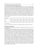
Table 1 shows the unit-cell dimensions and the dielectric substrate parameters to achieve the
indicated resonance frequencies and bandwidths of AMC performance. The three AMC
Troubleshooting RFID Tags Problems With Metallic Objects Using Metamaterials
175
designs use commercial dielectric substrates: Transtech MCT-25 with relative dielectric
permittivity ε
r
=25 and loss tangent less than 0.001, Rogers RO3010 with ε
r
=10.2 and loss
tangent 0.0035 and RO4003C with ε
r
=3.38 and loss tangent less than 0.0027.
Fig. 1. Simulation model and Reflection phase of the simulated AMC prototypes
The simulated reflection phase of normally incident plane wave (field strength 1 V/m) on
the AMC surface versus frequency for the designed unit cell geometry with the three
different dielectric substrates is shown in Fig. 1. The bandwidth of AMC performance
increases with the thickness of the dielectric substrate but decreases as the relative dielectric
permittivity gets higher values. The three presented designs (see Fig.1 and Table 1) show
broad bandwidth using neither via-holes nor multilayered structures, which simplifies
manufacturing process and reduces the costs.
It is remarkable that the broad AMC operation bandwidth of this specific unit cell geometry
makes possible its combination with an antenna without significantly reducing the antenna
bandwidth, which is the common drawback pointed out when dealing with AMC structures
due to their inherent narrow bandwidth.
Another major concern on AMCs operation is related to their angular stability (Simovski et al,
2005). This can be analyzed from two different points of view: the first analysis is performed
with regards to AMC operation under normal incidence condition when the polarization of
the incident field is varied. The second analysis is focused on the AMC performance under
oblique incidence. Both of them are very important because when combining the AMC with
the antenna, the angular stability of the AMC will influence the antenna radiation performance
and this will have direct impact on the angular reading range of the final RFID tag depending
on the position of the reader with respect to the tagged object. Following this, an AMC design
with as higher angular stability as possible is desirable.
Current Trends and Challenges in RFID
176
As pointed out in section 1, the negative effects of metallic objects in RFID tags are increased
at higher frequencies and so the following discussions are going to be focused on an AMC to
be used on 5.8GHz SHF RFID frequency band tags.
The reflection phase of the designed AMC surface has been simulated for different incident
field (E
inc
) polarization angles (φ). The unit cell design symmetry makes possible the AMC
to operate identically for any polarization of the incident field (assuming normal incidence),
as shown in Fig. 2. This also means that reflection phase of both TE and TM polarizations of
the incident wave will be identical for normal incidence.
Regarding AMC operation under oblique incidence, it can be extracted from Fig. 3 that
resonance conditions are met within an angular margin of θ
inc
= ±58º (due to the unit cell
design symmetry) for TE polarization. In this range the deviation of the resonance frequency
is less than 1%. For higher incident angles the resonance frequency shifts to another band. It
is also remarkable that the AMC operation bandwidth decreases from 7.20% to 3.39% as the
incident angle θ
inc
is increased from 0º to +58º. However, the 5.8GHz frequency of interest is
within the AMC operation bandwidth for all the incident angles in the θ
inc
= ±58º angular
margin. This means that there is almost a 120º angular margin in which the structure
performs as an AMC at 5.8GHz. For TM polarization, the angular margin reduces to θ
inc
=
±40º, the deviation of the resonance frequency is 6.83% and the AMC operation bandwidth
is preserved. So there is a 80º angular margin in which the structure performs as an AMC at
5.8GHz for both Te and TM polarizations of the incident wave, which can be considered as a
very stable AMC structure.
5 5.25 5.5 5.75 6 6.25 6.5
-180
-135
-90
-45
0
45
90
135
180
Frequency (GHz)
Reflection Phase (deg)
0º
15º
30º
45º
60º
90º
Fig. 2. Simulated Reflection phase of the AMC surface for different incident field (E
inc
)
polarization angles φ=0º, 15º, 30º, 45º, 60º and 90º.
It is important to point out that angular stability under oblique incidence depends not only
on the unit cell design geometry but also on the thickness of the dielectric substrate and on
Troubleshooting RFID Tags Problems With Metallic Objects Using Metamaterials
177
the unit cell size (periodicity) compared to the dielectric substrate thickness (Hosseini et al,
2006; Simovski et al, 2005).
Fig. 3. Simulated Reflection phase of the AMC surface for TE (up) and TM (down)
polarizations for different incident angles θ
inc
=0º, º, 30º, 45º, 55º and 58º.
Current Trends and Challenges in RFID
178
3. Antenna on AMC to be used in 5.8GHz SHF RFID tags over metallic objects
Firstly, a miniature printed CPW-fed slot antenna (Lin et al, 2005) for operating in the
5.8GHz frequency band has been designed (see Fig.4) using RO4003C, with ε
r
=3.38, loss
tangent less than 0.0027 and 0.813mm thickness, as dielectric substrate. A slot antenna has
been chosen because it will provide wider bandwidth making easier the combination with
the narrower bandwidth of AMC performance. There is no metallic layer under the antenna
dielectric substrate. This antenna has a simple structure with only one layer of dielectric
substrate and metallization.
The antenna dimensions together with simulated return losses for the antenna are shown in
Fig. 4. The simulated operating bandwidth of the antenna (range of frequencies with S11-
10dB) is 1.48GHz (22.0%).
Fig. 4. Return loss of the antenna; Geometry and dimensions; Manufactured prototype.
The simulated antenna gain at 5.8GHz is 5.0 dB with very small variation along the antenna
bandwidth (see Fig 5). The simulated E and H-plane radiation pattern in polar form for the
antenna at 5.8GHz are shown in Fig.5. Both the CP and the XP components are represented.
The E-plane radiation pattern is broadside and bidirectional. The H-plane radiation pattern
is almost omnidirectional.
Regarding the AMC arrangement with respect to the antenna, several ideas have been
considered. The first one is that the AMC used as antenna ground plane would
electromagnetically insulate the antenna from the metallic object, without disturbing the
antenna performance. The second is to minimize the size of the final prototype and to
facilitate manufacturing process.
Two AMC arrangements having respectively 5x5 and 5x4 AMC unit cells have been
combined with the CPW-fed slot antenna and the resulting prototypes (see Fig. 6) have been
tested in terms of return loss. In both cases the antenna is fixed to the AMC structure by a
0.1mm double sided non-conducting adhesive tape.
Troubleshooting RFID Tags Problems With Metallic Objects Using Metamaterials
179
E-plane (=90º)
H-plane (=0º)
5 5.25 5.5 5.75 6 6.25 6.5
2
2.5
3
3.5
4
4.5
5
5.5
6
Fre
q
uenc
y
(
GHz
)
Gain (dB)
E-plane (=90º)
H-plane (=0º)
E-plane (=90º)
H-plane (=0º)
5 5.25 5.5 5.75 6 6.25 6.5
2
2.5
3
3.5
4
4.5
5
5.5
6
Fre
q
uenc
y
(
GHz
)
Gain (dB)
Fig. 5. CPW-fed slot antenna simulated radiation pattern (normalized, in dB) CP (green) and
XP (red) components for E plane (up, left) and H plane (up, right). Three-dimensional
simulated radiation pattern (down, left). Simulated antenna gain (down, right)
Prototypes of the antenna and the antenna on AMC have been manufactured using laser
micromachining. The return losses of each manufactured prototype have been measured. As
it can be observed in Fig.4, the measured operating bandwidth of the slot antenna is 1.5GHz
(24.0%), which is wider than the 1.48GHz (22.0%) obtained by simulation. The difference in
bandwidth and the frequency shift could be due to manufacturing tolerances.
From the measurements results shown in Fig. 6 it can be concluded that although the
antenna on 5x5 AMC shows better return loss results than the antenna on 5x4 AMC at some
frequencies, both prototypes have the same operating bandwidth and the return loss of the
antenna on 5x5 AMC is also proper. So the increase of the prototype size due to the use of
5x5 unit cells is not profitable from the performance point of view. Taking this into account,
the 5x4 AMC has been selected to be combined with the CPW-fed slot antenna.
The selected AMC arrangement in terms of a trade-off between performance and size is the
one shown in Fig.7. The dimensions of the final structure, antenna on AMC (Fig. 7)), are
Lp=57.60mm and Wp=46.08mm. The thickness is 1.626mm in the part corresponding to the
antenna on the AMC and 0.813mm in the part corresponding only to AMC unit-cells.
Current Trends and Challenges in RFID
180
Fig. 6. Manufactured prototypes of the antenna on 5x5 cells AMC, the antenna on 5x4 cells
and the antenna (up). Return loss of the Antenna, the antenna on 5x5 cells AMC and the
antenna on 5x4 cells (down).
As it could be expected, when placed on a metallic plate the antenna resonance frequency
has been shifted out of the SHF RFID band leading to its total malfunctioning (see Fig.4.).
However, from Fig.7, it can be extracted that the antenna on AMC combination keeps the
antenna operating properly in the whole antenna bandwidth, even when placed on a
metallic plate, as the AMC electromagnetically insulates the antenna from the metallic plate.
The measured input return loss for the antenna on AMC prototype shows two resonances:
the first one is due to the joint operation of the antenna and the AMC, since the AMC
operation bandwidth starts at 5.625GHz (See Fig.1). Whereas the second resonance is due to
an antenna resonance out of the AMC operation bandwidth, since there is an additional
RO4003C metal-backed layer below the original antenna.
According to the measurements, metallic plates do not affect the resonance frequency of the
antenna on AMC. In addition, the metallic plates do not degrade the bandwidth of the
antenna on AMC.
Troubleshooting RFID Tags Problems With Metallic Objects Using Metamaterials
181
Fig. 7. Measured input return loss for the antenna and the antenna on AMC on a metallic
plate; manufactured prototype.
The radiation pattern of the manufactured prototypes has been measured in anechoic
chamber (see Fig. 8). The prototypes are placed in the XY plane. The measured antenna
radiation pattern is in very good agreement with the simulated one, as can be concluded by
comparing Fig 5 and Fig 10.
As can be observed in Fig 9, when the antenna is placed on the AMC, the maximum of the
radiation pattern is displaced (the direction of maximum radiation changes). However when
the antenna on AMC prototype is fixed over a metallic plate, this maximum is preserved
with respect to the antenna on AMC prototype. As could be expected, the back radiation of
the antenna on AMC is reduced with respect to the antenna prototype due to the in phase
reflection properties of the AMC. So despite the small AMC structure, the antenna on AMC
has a relatively low back radiation. Radiation pattern properties of the Antenna on AMC for
RFID application are still preserved even when placed on a metallic plate.
Prototype Gain (dB)
Pattern directivity
(dB)
Efficiency (%)
Antenna 4.2 6.3 59.8
Antenna on AMC 2.2 7.0 32.0
Antenna on AMC over
metallic plate
3.8 10.0 22.7
Table 2. Measured gain, directivity and radiation efficiency of the manufactured
prototypes.
Current Trends and Challenges in RFID
182
Fig. 8. Measurement set-up in anechoic chamber. Antenna measurement (left) and antenna
on AMC over metallic plate measurement (right).
Fig. 9. Three-dimensional representation of the normalized measured radiation pattern for
the three manufactured prototypes: antenna (left), antenna on AMC (center) and antenna on
AMC over metallic plate (right)
In addition, the gain of the antenna on AMC fixed over a metallic plate almost preserves
with respect to the gain of the antenna alone as it is shown in table 2, which represents a
significant achievement.
In general, when placing an antenna on an AMC radiation properties such as gain and
radiation efficiency are enhanced with respect to the antenna alone. This is due to the fact of
using the AMC as a ground plane for the antenna substituting a conventional metallic
ground plane i.e. antenna topologies that already have a metallic ground plane under the
antenna metallization, such as microstrip patch antennas. As pointed out in section 1, these
antennas can perform well with metallic objects but have narrow bandwidth and not
negligible thickness. Other approaches combining antennas without metallic layer under the
dielectric substrate (such as CPW-fed antennas) with AMCs for gain enhancement purposes,
separate the antenna from the AMC by using an additional layer of foam. This also increases
the antenna thickness which is not convenient in RFID applications. However, the slot
Troubleshooting RFID Tags Problems With Metallic Objects Using Metamaterials
183
YZ-plane (=90º)
XZ-plane (=0º)
YZ-plane (=90º)
XZ-plane (=0º)
Fig. 10. Measured radiation pattern (normalized, in dB) of antenna, antenna on AMC and
antenna on AMC over metallic plate. Planes = 90º (YZ-plane) and = 0º (XZ-plane).
antenna presented here has no metallic layer under the dielectric substrate and so when
placing the AMC directly under the antenna to electromagnetically insulate the antenna
from the metallic object, the antenna performance is slightly disturbed to some extent in
terms of gain and radiation efficiency (see table II), whereas the obtained prototype exhibit
proper operation over metallic objects and the gain is almost preserved compared to the
antenna operating alone. All these properties are suitable for RFID application.
Another possibility tested to try to obtain enhanced efficiency (or at least preserved it) is to
remove the AMC’s unit cells below the antenna but this significantly reduces the antenna
bandwidth as can be seen in Fig. 11 and the resonance at 5.8GHz disappears. For this reason
the use of this arrangement has been declined. The only resonance that appears is at
6.45GHz and it is due to antenna having and additional dielectric substrate layer and a
metallic ground plane bellow this dielectric substrate layer.
Also the antenna could be centred on the AMC arrangement which might preserve and/or
enhance the radiation properties of the antenna, but this would require changing the
antenna feeding increasing the complexity of the prototype and also its cost. The aim of this
chapter it is to show that it is possible to obtain a compact, low profile and low cost antenna
on AMC combination proper to be used over metallic objects.
4. Conclusion
A novel CPW-fed-slot antenna on AMC combination prototype suitable to be used in 5.8
GHz RFID tags on metallic objects has been presented. It has been shown that metallic plates
Current Trends and Challenges in RFID
184
Fig. 11. Measured input return loss for the antenna and the antenna on AMC when the unit
cells under the antenna are removed.
do not affect the resonance frequency of the antenna on AMC. In addition, the metallic
plates do not degrade the bandwidth of the antenna on AMC.
As a reward for the AMC addition, the manufactured prototype, using a thin and low
dielectric permittivity commercial substrate, exhibits proper operation both alone and when
placed on a metallic plate.
The presented CPW-fed-slot antenna on AMC combination meets most of the RFID tag
antennas requirements pointed out in section 1. Further research is being carried out to
obtain a prototype in a bendable dielectric substrate.
By using the other presented AMC designs for UHF and 2.4GHz SHF with antennas
operating at those frequency bands, problems related to RFID tags operation with metallic
objects can be overcome.
5. Acknowledgment
Authors thanks Ramona C. Hadarig and Dr Yuri Álvarez for their comments and useful
discussions. This work has been supported by the “Ministerio de Ciencia e Innovación” of
Spain /FEDER” under projects TEC2008-01638/TEC (INVEMTA) and CONSOLIDER
CSD2008-00068 (TERASENSE), by PCTI Asturias under project, PEST08-02 (MATID) and by
the Principado de Asturias/FEDER Project IB09-081 (CAMSILOC).
6. References
Clarke R., Twede D., Tazelaar J., Boyer K., Radio frequency identification (RFID)
performance: the effect of tag orientation and package contents, Packaging
Technology and Science vol. 19, no. 1, 2006, pp. 45-54.
Troubleshooting RFID Tags Problems With Metallic Objects Using Metamaterials
185
Dobkin D. M., Weigand S. M., Environmental effects on RFID tag antennas, IEEE
Microwave Symposium Digest, Jun. 2005, pp. 135-138.
Feresidis, A. P., Goussetis G.,Wang S., and Vardaxoglou J. C., Artificial magnetic conductor
surfaces and their application to low profiles high-gain planar antennas. IEEE
Trans. Antennas Propag., Vol.53, no.1, 209-215, 2005.
Finkenzeller K., RFID Handbook: Radio-Frequency Identification Fundamentals and
Applications, 2nd ed.: Wiley, 2004.
Foster P.R. and Burberry R.A., Antenna problems in RFID systems, IEE Colloquium on RFID
Technology, pp. 3/1–3/5, October 1999
Geyi, W., Derivation of Equivalent Circuits for Receiving Antenna, IEEE Transactions on
Antennas and Propagation, vol. 52, no. 6, pp. 1620-1623, June 2004.
Goussetis G., Feresidis A. P. and Vardaxoglou J. C., Tailoring the AMC and EBG
Characteristics of Periodic Metallic Arrays Printed on Grounded Dielectric
Substrate, IEEE Trans. Antennas Propag., Vol.54, no.1, pp. 82-89, Jan 2006.
Hirkonen M., Pursula, P. Jaakola K., and Laukkanen K., Planar inverted-F antenna for radio
frequency identification, Electronic. Letters., vol. 40, pp. 848-849, July 2004.
Hosseini M., Pirhadi A. and Hakkak M., A Novel AMC with Little Sensitivity to the angle of
Incidence Using 2-layer Jerusalem Cross FSS, Progress In electromagnetics
Research, PIER 64, 43-51, 2006.
Kern, D. J., Werner, D. H., Monorchio, A., Lanuza, L. and Wilhelm, M. J., The design
synthesis of multiband artificial magnetic conductors using high impedance
frequency selective surfaces, IEEE Trans. on Antennas and Propag., Vol.53, No. 1,
Jan. 2005.
Kwon H. and Lee B., Compact slotted planar inverted-F RFID tag mounted on metallic
objects, Electronic Letters, vol. 41, pp. 1091-1092, Nov. 2005.
Liang J. and Yang H Y. D., Radiation Characteristics of a Microstrip Patch Over an
Electromagnetic Bandgap Surface. IEEE Trans. on Antennas and Propag., Vol. 55,
No 6, June 2007
Lin Y.F, Liao P.C., Cheng P.S., Chen H.M., Song C.T.S. And Hall P.S., CPW-fed capacitive H-
shaped narrow slot antenna, Electronic Letters, vol.41, No.17, 2005
Mantash M., Tarot A.C., Collardey S. and Mahdjoubi K., Dual-band antenna for WLAN
application with EBG. Fourth International Congress on Advanced Electromagnetic
Materials in Microwaves and Optics. Metamaterials 2010. pp. 794-796, Sep.2010.
Mantash M., Tarot A.C., Collardey S. and Mahdjoubi, K., Dual-band CPW-fed G-antenna
using an EBG structure, Antennas and Propagation Conference (LAPC), 2010
Loughborough. pp. 453 – 456.
McVay J., Engheta N. and Hoofar A., High impedance metamaterials surfaces using Hilbert-
curve inclusions, IEEE Microw. Wire. Comp. Lett., vol.14, no.3, 130-132, 2004.
McVay J., Hoofar A. and Engheta N., Small dipole-antenna near Peano high-impedance
surfaces, IEEE AP-S Int. Symp.,vol 1., 305-308, 2004.
Monorchio A., Manara G., and Lanuzza L., “Synthesis of artificial magnetic conductors by
usisng multilayered frequency selective surfaces”, IEEE Ant. Wireless Propag,
Lett.,vol1, pp.196-199, 2002.
Mosallaei H. and Sarabandi K.,Antenna Miniaturization and Bandwidth Enhancement
Using a Reactive Impedance Substrate, IEEE Trans. on Antennas and Propag,
Vol.52, No.9, September 2004.
Current Trends and Challenges in RFID
186
Pozar, D., Scattered and Absorbed Powers in Receiving Antennas, IEEE Antennas and
Propagation Magazine, vol. 46, no. 1, pp.144-145, February 2004.
Rahmat-Samii, Y.; Mosallaei, H.,”Electromagnetic band-gap structures: clasiffication,
characterization, and applications”, Eleventh International Conference on
Antennnas and Propagation, 2001. (IEE Conf. Publ.No.480) vol. 2, 2001. Page(s):
560-564;
Rao, K. V. S., An overview of Backscatter Radio Frequency Identification System (RFID),
IEEE Asia Pacific Microwave Conference, vol.3, pp. 746-749, November-December
1999.
Rao K. V. S., Nikitin Pavel V., Lam Sander F. Antenna Design for UHF RFID Tags: A Review
and a Practical Application, IEEE Transactions on Antennas and Propagation, vol.
53, no.12, pp. 3870-3876, December 2005.
Rao K. V. S., Nikitin Pavel V., Lam Sander F., Impedance Matching Concepts in RFID
Transponder Design, Proceedings of IEEE Workshop on Automatic Identification
Technologies, Oct. 2005, pp. 39-42.
Sievenpiper D., High-impedance electromagnetic surfaces, Ph.D. Thesis. University of
California. Los ángeles, 1999.
Sievenpiper, D., L. Zhang, R. F. J. Broas, N. G. Alexopolous, and E. Yablonovitch, High-
impedance electromagnetic surfaces with a forbidden frequency band, IEEE Trans.
Microwave Theory and Techniques. vol.47, no.11, pp.2059-2074, Nov.1999
Simovski, C. R., de Maagt, P. and Melchakova, I. V., High-Impedance Surfaces Having
Stable Resonance With Respect to Polarization and Incidence Angle, IEEE Trans.
Microwave Theory and Techniques. Vol.53, No. 3, pp. 908-914, March 2005.
Stockman H., Communication by means of reflected power, Proc. IRE, pp 1196-1204,
Oct.1948.
Ukkonen L. et al., Operability of Folded Microstrip Pach-Type Tag Antenna in the UHF
RFID Bands within 865-928 MHz, IEEE Antennas and wireless Propagation Letters,
vol. 5, 2006.
VanBladel, J., On the Equivalent Circuit of a Receiving Antenna, IEEE Antennas and
Propagation Magazine, vol. 44, no. 1, pp. 164-165, February 2002.
Yang, F. and Rahmat-Samii Y., Reflection phase characterizations of the EBG ground plane
for low profile wire antenna applications, IEEE Trans. Antennas Propag., Vol. 51,
No. 10, 2691-2701, 2003.
Yang, F. R., Ma K. P., Qian Y., and Itoh T., A uniplanar compact photonic-bandgap (UC-
PBG) structure and its applications for microwave circuit, IEEE Trans. Microwave
Theory Tech., vol 47, no.8, 1509-1514, 1999.
Yang F. and Rahmat-Samii Y., Electromagnetic band-gap structures in Antenna Engineering
(The Cambridge RF and Microwave Engineering Series). Cambridge University
Press. 2008.
Zhang Y., J. von Hagen, and W. Wiesbeck, Patch array as artificial magnetic conductors for
antenna gain improvement, Microw. Opt. Technol. Lett., vol.35, no. 3, 172-175,
2002.
Zhu S. and R. Langley, Dual-Band Wearable Textile Antenna on an EBG Substrate, IEEE
Transaction On Antennas and Propag., Vol.57, No. 4, April 2009.
10
High Performance UHF RFID Tags for
Item-Level Tracing Systems
in Critical Supply Chains
Luca Catarinucci, Riccardo Colella, Mario De Blasi,
Luigi Patrono and Luciano Tarricone
University of Salento
Italy
1. Introduction
The need of a traceability system implemented at item level is becoming more and more
essential in many business processes and, among the different potential enabling
technologies, passive Radio Frequency Identification (RFID) (Finkenzeller, 2003) is
undeniably the most adequate candidate. Indeed, its simplicity of use as well as its very
attractive cost-benefit ratio, give a strong appeal to RFID.
Among the many application sectors, the pharmaceutical supply chain, with millions of
medicines moving around the world and needing to be traced at item level, represents a
very interesting test-case. Furthermore, the growing counterfeiting problem raises a
significant threat within the supply chain system. Moreover, several international
institutions (e.g. Food and Drug Administration, European Medicines Agency, European
Federation of Pharmaceutical Industries and Associations) are encouraging the use of
innovative solutions in healthcare and pharmaceutics, to improve patient safety and
enhance the efficiency of the pharmaceutical supply chain.
In order to select the most adequate hardware solution, though, several aspects must be
compulsory taken into account, including the working frequency, the near or far field
empowering methods, but also the differences among the various RFID-based checkpoints
of a generic supply chain (De Blasi et al., 2009; Uysal et al., 2008).
The choice between the two main RFID solutions, High Frequency (HF) or Ultra High
Frequency (UHF), can be aided by several recent works, which highlight how passive UHF
RFID systems provide better performance than passive HF ones, see for example (Uysal et
al., 2008). Hence, UHF seems to be the most promising technology for item-level traceability
on the whole supply chain. The success of UHF can be mainly attributed to the assertion of
the EPCglobal (Thiesse et al., 2009) international standard. Furthermore, UHF has several
advantages over HF and LF technologies: the capability to enable multiple simultaneous
readings of tags, the capacity to offer very high read rates, in addition to the much longer
reading distance.
Unfortunately, performance of UHF systems depends on several parameters (Bertocco et al.,
2009), which are strongly related to environment, design and setup choices. For example, it
is well known that a supply chain is composed of several steps that have different
Current Trends and Challenges in RFID
188
characteristics in terms of traceability procedures (e.g., distance between reader antenna and
tag antenna, speed of moving objects, quantity of tags to be read, etc.). In such scenarios, the
choice of an RFID tag solution, able to guarantee high performance in each step of the
supply chain and in any operating condition, is certainly a hard challenge.
Some approaches proposed in literature, are based on the use of general-purpose Far Field
(FF) UHF tags (Rao et al., 2005; Catarinucci et al., 2010) applied on the secondary package of
the product. Several studies, in fact, have shown that the use of FF UHF tags guarantees
better performance than Near Field (NF) ones in every step of the supply chain. Indeed, as
most of FF UHF tags are provided with an inner loop that short-circuits the tag chip
technology (hybrid tags), they exhibit good performance even in near field conditions. In
fact, this strategy allows an efficient coupling with the magnetic field generated by NF
reader antennas (Catarinucci et al., 2010).
In addition to the RFID checkpoints peculiarities, another important aspect is the effect on
the tag performance of the platform where the tag is attached. Unfortunately, commercial FF
UHF tags still suffer of many drawbacks (Nikitin & Rao, 2006). First of all, they suffer of
performance degradation in presence of electromagnetically hostile materials, such as
metals and liquids (Catarinucci et al., 2010; De Blasi et al., 2010). Another issue regards the
strong dependence of the system performance on the mutual position between reader
antenna and tag antenna, which may vary randomly for each item. Consequently, from the
electromagnetic (EM) point of view, very strict requirements must be satisfied by the tag
antenna.
The sum of the requirements to be met by a single tag, functioning properly in every step of
the supply chain, will be extended in the next sections.
Consequently, the first part of this chapter describes the main features of the pharmaceutical
scenario, mainly focusing on item-level tracing systems, RFID devices performance, related
works and experimental measurement campaigns of commercial UHF RFID tags.
Taking into account the analysis of such aspects, the main causes of performance
degradation are individuated and a guideline for the design of a new kind of RFID tag,
working properly in each step of the pharmaceutical supply chain and regardless of the
kind of traced product, has been drawn in the second part of this chapter. Moreover, a new
enhanced tag has been realized by following the guideline, tested, and finally results have
been discussed.
2. Related works
The current vision of the RFID market shows, in addition to UHF FF tags already widely
used, also the presence of UHF NF tags. These last are based on inductive rather then
radiative coupling and usually are energized by specific NF reader antennas, appositely
designed to minimize the radiated field. The tag antenna is usually a simple loop, whose
diameter is calculated in order to guarantee the resonance at the desired frequency —a few
centimeters in the UHF band—, but also more complicated shapes do exist. The short range
of both NF reader antennas and small loop antennas restrict the NF tags reading range to
only a few centimeters. Nevertheless, the smaller size of NF tags and the higher tolerance to
the scenario —inductive field penetrates through liquids and dielectrics— make them useful
in some applications where the size is crucial and marked items are electromagnetically
complex.
It is important for the scientific community to understand the capabilities and limitations of
the emerging passive UHF technology, and just as importantly, to understand where
High Performance UHF RFID Tags
for Item-Level Tracing Systems in Critical Supply Chains
189
researchers may contribute to face problems and challenges that currently are limiting a
large-scale deployment of this technology. Main barriers are: (i) hardware technology
current weaknesses (Catarinucci et al., 2010) (e.g. data reliability, read rate in critical
conditions, lack of unified standard for interoperability), (ii) software weakness (Barchetti et
al., 2010) (e.g. scalability, single-point of failure, integration with information systems), (iii)
relatively high costs of tags, software customization and systems integration, (iv) security
issues (Staake et al., 2005; Mirowski et al., 2009), (v) lack of scientific literature on the
evaluation of potential effects of RFID exposure on molecular structure and potency of
drugs (Acierno et al., 2010).
There is a rich literature about developing and evaluating UHF RFID solutions.
(Aroor & Deavours, 2007), for instance, evaluates performance of several commercial
passive UHF tags under critical operating conditions (e.g. presence of liquids and/or
metals) by using an experimental approach. In order to simplify both measurements and
result analyses, an end-user metric has been chosen. In particular, performance of tags is
measured in terms of maximum reading distance in a given environment. The tests have
demonstrated that no commercial FF UHF tag can be properly read when it is directly
applied to metal. Further results have shown that the water presence degrades the tag
performance significantly. The tests have also demonstrated that larger tags guarantee better
performance. In the same work, a series of experiments has also been carried out by using
some NF UHF tags. The results have clearly demonstrated that NF UHF tags do not solve
the problem associated with the presence of neither the metal nor the water. On the
contrary, it has been highlight that the presence of metal or water has even much more
drawbacks in NF rather than FF UHF tags.
(Bertocco et al, 2010) experimentally investigates the relationships between the EM field
levels at the tag antenna and the overall performance of a UHF RFID system. The results
have underlined the importance of preliminary measurements in the setup of the system, in
the evaluation of the maximum distances between tags and reader antenna, and in the
estimation of a correction factor to be used in theoretical analyses.
(Ramakrishnan & Deavours, 2006) describes a benchmark suite useful to give good
indications about how well UHF solutions work in real world scenarios. These benchmarks
are able to compare the reading performance of different tags in terms of distance, quality,
and real rates in various situations.
(Fuschini et al., 2010) is another work that aims at investigating the main benefits and
performance of NF UHF tags in item-level tagging systems. This study exploits an
electromagnetic analysis based on both theoretical evaluations and measurements carried
out on real UHF RFID devices. Four different commercial tags (i.e. Alien Squiggle, Texas
Instruments, Impinj Button, and Impinj Satellite) have been tested mainly in terms of the
system Path Gain, defined as the ratio between the power absorbed by the tag and the
available power at the reader. The results have demonstrated no particular electromagnetic
benefits in performance in favour to NF UHF tags.
(Tae-Wan Koo, et al., 2010) is a very interesting work focused on the need to improve the
performance when an UHF tag is applied on a metallic object.
(Bertocco et al., 2009) highlights the importance to evaluate the performance of UHF RFID
systems in real-world conditions by using suitable test bed to perform the experiments. In
particular, the system efficiency is considered. This work asserts that there are many
parameters that should be known and tuned to maximize the efficiency even in critical
Current Trends and Challenges in RFID
190
conditions. Some measurements have demonstrated that the deployment of multiple
antennas might be totally useless. On the contrary, better results can be obtained using
reflecting surfaces, or deploying reading-paths, avoiding reading-gates.
(De Blasi et al., 2010) is focused on the use of passive UHF tags, in order to analyze a
performance comparison between near field and far field UHF RFID systems in every of the
pharmaceutical supply chain. Some different commercial passive UHF tags (i.e. Impinj Thin
Propeller, Impinj Paper Clip, and RSI Cube2) have been tested in an item-level system,
simulating each step of the pharmaceutical supply chain in a controlled test environment.
Results allow to analyze the advantages and disadvantages of using NF and FF UHF tags
for item-level tracing in each step of the pharmaceutical supply chain. Experimental results
show that the use of passive FF UHF tags represent a well suitable solution to guarantee
both high performance and item level tagging in the whole supply chain. This work
highlights also that the pharmaceutical supply chain is characterized by very critical
operating conditions where tag improvements are strongly needed in order to guarantee
acceptable performance.
3. Test environment to emulate a pharmaceutical supply chain
3.1 Reference scenario
The pharmaceutical supply chain, shown in Fig. 1, is a complex scenario with millions of
pharmaceutical products moving around the world each year. Three are the most significant
actors of such a supply chain: (i) the manufacturer who produces the package of
pharmaceuticals, (ii) the wholesaler who buys and resells big quantities of medicinal
products, and (iii) the retailer, which in general is a pharmacy or hospital.
Fig. 1. An abstract vision of the pharmaceutical supply chain.
The item-level traceability of drugs starts just after the packages are filled during the
manufacturing process. In this step, each tagged product is individually scanned on the
conveyor belt and then cased to be sent to the wholesalers. The wholesalers separate the
products according to their identifiers and place them onto the shelves. Wholesalers receive
orders from retailers. Such orders often refer to small quantities of many products; they may
contain a large number of items. The products in the orders of the retailers are picked and
put into some large envelope bags that are scanned and confirmed before their distribution.
Upon receipt, the pharmacy retailer scans the contents of each bag without opening it.
In order to select the most adequate RFID hardware solution, though, several aspects must
be compulsory taken into account, including the working frequency, the near or far field
empowering methods, but also the differences among the various RFID-based checkpoints
of a generic supply chain.
In fact, depending on the considered step of the supply chain, at least three different RFID
checkpoints are commonly used. They differ each other in terms of interrogation distance,
High Performance UHF RFID Tags
for Item-Level Tracing Systems in Critical Supply Chains
191
number of items to be read, reader antenna typology and scanning speed. It is worth
pointing out that the tag marking an item must work properly in all checkpoints.
More specifically, one of the possible checkpoints is given by the so-called items line, where
the tagged product must be singularly scanned by using NF reader antennas. Whatever tag
is used for the item-level traceability, it should guarantee good performance even in near
field conditions.
A second kind of checkpoint is given by the so-called cases line, where a case containing a
number of homogeneous items packed together, passes through a NF tunnel in order to
read all the items in one shot. Consequently, the RFID tags used to assure reliable item-level
tracing systems should work correctly even at medium distance from the interrogator
antennas. Moreover, the problem of the multiple readings of tags and of the tag overlapping
should be considered.
A third kind of checkpoint is given by the so-called border gate. When a pharmacy retailer is
restocked it becomes necessary to simultaneously read all the different tagged items
contained in a box or in a plastic bag. The border gate, equipped with FF reader antennas, is
designed for such a purpose.
Besides the RFID checkpoints peculiarities, another important aspect is the effect on the tag
performance of the platform where the tag is attached. UHF tags, more than HF ones, are
influenced by the presence of electromagnetically hostile materials, such as liquids and
metals; this aspect is crucial because in several scenarios, as the considered pharmaceutical
one, metals and liquids are massively present.
3.2 Test bed components
The controlled test environment, shown in Fig. 2, has been realized in order to simulate the
main steps of the pharmaceutical supply chain. Such a test environment, in fact, makes it
possible to carry out effective experimental campaigns to evaluate the performance of UHF
RFID-based tracing systems, even in particularly stressed operating conditions.
The test environment, based on the three main components above described (items line,
cases line and border gate), makes possible unbiased and repeatable comparisons among
technologies.
More specifically, the items line consists of a conveyor belt whose speed can be tuned in the
range from 0.00 to 0.66 m/s, in order to guarantee real requirements to be met by
pharmaceutical manufacturing processes. The conveyor belt has a double containment edge
to keep products in the same position along the belt. In the middle of each containment
edge, a near field reader antenna has been installed and connected to a high performance
UHF RFID reader compatible with the EPC Class1 Gen2 standard. The following devices
have been used: two Impinj Mini-Guardrail reader antennas and one Impinj Speedway UHF
reader.
Similarly, the cases line consists of a conveyor belt, equipped with a line speed regulator in
the range from 0.00 to 0.66 m/s, a double containment edge to keep cases in the same
position along the belt, one Impinj Speedway reader, and two roller conveyors. In the
middle of the line, four small near field reader antennas (Impinj Brickyard) have been
placed inside a metallic tunnel. Each reader antenna is in the centre of each tunnel side. The
width of the tunnel is equal to 0.6 m. Further characteristics are: 50 of impedance, 6 dBi as
maximum far field gain and -15 dB as Return Loss.
Finally, the border gate uses a single UHF RFID reader (Impinj Speedway) and four far field
UHF reader antennas.
Current Trends and Challenges in RFID
192
Fig. 2. Test environment composed of an items line (left), a cases line (middle), and a border
gate (top right).
In order to effectively simulate the pharmaceutical supply chain, it is very important to take
into account real heterogeneous drugs, so to significantly represent the global market of
drugs, that is characterized by a wide heterogeneity of products, which differ for several
factors as, for instance, medicine state (i.e. solid, liquid, gas, etc.) and material of the primary
package (e.g. glass, metal, plastic, etc.). A complete taxonomy of most popular drugs may be
done by considering these factors.
The first classification, which takes into account only the medicine state, splits all
pharmaceutical items into four main categories:
Solid: tablets capsules, granules, etc.
Semi-liquid: creams, suppositories, etc.
Liquid products: syrups, oral liquids, solutions, etc.
Gas: pressurized gasses.
Another useful classification can be done in terms of material of the primary package.
Plastic is the most widely diffused material because of the large use of bottles, blister packs,
and film layers. Nevertheless, even the use of metal is fairly common: aluminium blister
packs and sachets are possible examples. Another common material for pharmaceutical
products is glass that is very valuable especially for the liquid products. Classical
applications of glass packaging are bottles for liquids, ampoules, and vials.
Based on the above information and discussions, Table 1 summarizes a simple taxonomy of
pharmaceutical products according to their physical properties.
It is worth observing that this classification is very important to perform significative tests
because different materials interact with RF waves differently. In particular, liquids cause
the RF waves attenuation by absorbing their energy, whereas metals do not let RF waves
High Performance UHF RFID Tags
for Item-Level Tracing Systems in Critical Supply Chains
193
pass through by reflecting them. Moreover, in both cases, the impact on the radiating
properties of RFID tag antennas is relevant. The reported taxonomy, hence, becomes a
compulsory instrument to select the most adequate drug for the specific laboratory test, so
as to evaluate the impact of hostile materials on the performance of the RFID systems in the
UHF band.
Product Type
Package Material
Metal Glass Plastic
Solid
Tablets in Blister X
Tablets in a Bottle X
Granules in Sachets X
Powders in a Bottle X
Semi-liquid
Cream X X
Liquid
Syrup X
Single injectable
solution in syringe
X
Multiple injectable
solution in syringes
X
Oral solution X
Ophthalmic solution X
Gas
Bomb Spray X
Table 1. Classification of pharmaceutical products
3.3 Description of the working conditions
An effective evaluation of RFID reliability in a pharmaceutical supply chain cannot neglect
the effects on the performance caused by hostile factors such as: the potential misalignments
between tag antenna plane and reader antenna plane, multiple reading of tags, distance
between tag antenna and reader antenna.
The misalignment problem is mostly relevant in the items line. To test such a misalignment
impact, four different operating conditions should be tested. They are characterized by a
mutual orientation between the plane where the tag antenna lies and the plane where the
reader antennas lie: 0°, +90°, -90° and 180° are considered. In particular, this last represents
the worst case and allows the performance evaluation under unfavourable conditions. Vice
versa, the 0° case is the ideal condition. Finally, the -90° case is characterized by the contact
between tag and conveyor belt. Instead, in the +90 ° case the tag is attached to the up-side of
the item, so that the potential interference with the conveyor belt is avoided but the distance
with the reader antennas depends on the size of the item.
Another problem to be analyzed deals with the collisions among tags, impacting both the
cases line and the border gate. For the cases line both homogeneous cases (consisting of a
single product type) and heterogeneous cases (containing products of different types)
should be tested. Moreover, also the configuration of the cases plays an important role. In