Advances in Mechatronics Part 7 pptx
Bạn đang xem bản rút gọn của tài liệu. Xem và tải ngay bản đầy đủ của tài liệu tại đây (609.21 KB, 20 trang )
5
Integrated Mechatronic Design for
Servo Mechanical Systems
Chin-Yin Chen
1
, I-Ming Chen
2
and Chi-Cheng Cheng
3
¹Taiwan Ocean Research Institute, National Applied
Research Laboratories, Kaohsiung, Taiwan R.O.C.
²School of Mechanical & Aerospace Engineering, Nanyang
Technological University, Singapore
3
Department of Mechanical and Electro-Mechanical Engineering,
National Sun Yat-Sen University, Kaohsiung, Taiwan R.O.C.
1,3
Taiwan
2
Singapore
1. Introduction
Mechatronic systems typically exhibited high a degree of complexity due to the strong cross
coupling of the involved different engineering disciplines such as mechanical, electronic and
computer. This complexity originates from the large number of couplings on various levels
of the contributing elements and components, coming from different disciplines. The
difficulty for the design engineer in his daily work is that these couplings have to be
considered in an early phase of the design process. With shortening product lift cycle,
design managers are consistently trying to identify means for producing a better product in
a shorter period of time.
Therefore, the realm of Mechatronics is high speed, high precision, high efficiency, highly
robust. The difficulty in the Mechatronic approach is that it requires a system perspective:
system interactions are important, system modeling is required, and feedback control
systems can go unstable. Mechatronic design concepts include direct-drive mechanisms,
simple mechanics, system complexity, accuracy and speed from controls, efficiency and
reliability from electronics, and functionality from microcomputers. Starting at design and
continuing through manufacture, Mechatronic designs optimize the available mix of
technologies to produce quality precision products and systems in a timely manner with
features the customer wants. The real benefits to industry of a Mechatronic approach to
design are shorter development cycles, lower costs, and increased quality, reliability, and
performance [25].
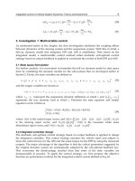
Additionally, in order to evaluate concepts generated during the design process, without
building and testing each one, the mechatronics engineer must be skilled in the modeling,
analysis, and control of dynamic systems and understand the key issues in hardware
implementation. Thus, as the Fig. 1 shows, the essential characteristic of a mechatronics
engineer and the key to success in mechatronics system is a balance between two sets of
skills [22]:
Advances in Mechatronics
110
Mechatronic system design process
Integrated Modeling
and Analysis
Experimental and
Implementation
Fig. 1. Balance of mechatronic design process [22].
1.1 Integrated modeling and analysis of dynamic mechatronic systems
During the design of mechatronic systems, it is important that changes in the mechanical
structure and the controller be evaluated simultaneously [24]. Although a proper controller
enables building a cheaper mechatronic system, a badly designed mechanical system will
never be able to give a good performance by adding a sophisticated controller. Therefore, it
is important that during an early stage of the design a proper choice can be made with
respect to the mechanical properties needed to achieve a good performance of the controlled
system. On the other hand, knowledge about the abilities of the controller to compensate for
mechanic imperfections may enable that a cheaper mechanical structure be built. This
requires that in an early stage of the design a simple integrated model is available, that
reveals the performance limiting factors of the mechatronic system.
Consequently, in order to help mechanical structure and controller of mechatronic system
modeling simultaneously, the mechatronic system design methods must be integration.
Accordingly, some of numerical based integrated design strategies for mechatronic system
were proposed to some fields such as: aerospace [1-3], robotics [4-6] and manufacturing
systems [7-8] in the early years. However, the dynamic models derived with the above
integrated methods typically have a high order. A critical issue in the mechanical structure
and control modeling with the integrated design approach is difficulty from each domain.
Therefore, for complex multibody systems of mechatronics, graphical modeling software is
helpful to formulate automatically the equations of motion from a high-level description.
Among the computer modeling methods, symbolic methods allow to build the equations of
motion in symbolic format, whereas numerical methods produce the equations of motion as
complex numerical procedures. The symbolic format has the advantages of portability and
efficiency, and it provides interesting insights in the analytical structure of the equations.
However, numerical methods are able to deal with a more general class of problems, and
they are especially suitable to model the dynamics of a flexible mechanism with complex
topology in a systematic way. After this clarification, let us further characterize the
modeling requirements in the design procedure, which are directly associated with the
objectives of this research
1.2 Experimental validation and hardware implementation of designs
In an industrial process, design of controllers involve formulation of reasonably accurate
models of the plant to be controlled, designing control laws based on the derived models
and simulating the designed control laws using available simulation tools such as
MATLAB/Simulink. Whereas implementation is accomplished by converting the designed
Integrated Mechatronic Design for Servo Mechanical Systems
111
control laws to the native code of target systems, most commonly embedded microprocessor
based architecture or personal computer with analog and digital interfaces. Controllers can
be designed in the continuous, discrete or hybrid time domain whereas implementation is
accomplished mostly in discrete time domain as most of the present day controllers are
being implemented in digital machines. Presence of the vast difference in design and
implementation of control applications is inherent due to different concepts in the field of
control engineering and computer science. Thus, transformation of controller designs to
implementation induces possibilities of errors and unreliable behaviors. In some cases, these
errors cannot be identified by rigorous tests of the implementation thus these errors results
in failure of the system causing serious and even catastrophic disaster.
Furthermore, the typical controller design task requires selection of controller strategies,
structures and parameter values. Before implemented engineers should be tested using
actual plant data or in prototype implementation with physically measured inputs and
generated outputs. This phase is necessary for experimental validation of model
simplifications and other assumptions made when designing the controller. On the other
hand, real-time simulation provides the best conditions for performance tuning. However,
sometimes the reverse situation occurs when plant model is substituted for the actual plant
while the controller might be fully implemented. This approach is called Rapid Controller
Prototyping (RCP) simulation [9–11]. For this technique, engineers have actuators, sensors
and other physical components interfacing with real-time simulation. Furthermore, RCP
techniques allow implementing and validating control strategies during the development
process that users can work within the same environment from the requirement analysis to
the controller design and implementation phase.
According to those two sets of skills, in the mechatronic design process, it can be broadly
categorized into three stages in a computer-supported design environment, namely, the
design problem of understanding behavior of mechatronic system through an analysis of
need, initial solution generation through conceptual design, and solution refinement and
finalization through multi-discipline detailed design. In computer support for engineering
design, there is little support for the first two stages in the design process, primarily due to
the complexity and diverse needs of these design activities during the three stages. The final
stage in the design process is currently the main area that has reasonable computer support,
and can be used to assist engineer designers to improve their designs or products. This stage
of computer support can be further decomposed into component modeling, component
matching and sizing, and behavior simulation and comparison for informative decision-
making. This decomposition facilitates further investigation of the constituents of each
design support activity.
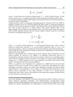
Notably, one typical problem with many current computer-modeling methods is that they
are extremely domain dependent. In the mechatronic system design processes, which
include structural design, controller design and implementation in three domains, also
consider interactions among multiple domains, such as integrated design, rapid prototyping
and animation technology (Fig. 2). Therefore, mechatronic design engineers must to be
trained to use in different application domains such that they would be competent in using
all these domain-dependent technologies. This task itself is very challenging. Consequently,
to solve dependent problems for mechatronic systems, mechatronic engineers always use a
dynamic equation that includes all parameters in the structural and control domains.
Unfortunately, one of the most significant problems when using equation-based
mechatronic modeling is the amount of modeling data that must be analyzed during the
Advances in Mechatronics
112
process. Because of this enormous amount of data and the numerical algorithm that must
also be utilized, this method of modeling and simulation is typically very slow and prone to
errors. Additionally, this method requires excellent knowledge of numerical solution
methods and programming principles.
Based on those reasons, in order to easy integrated design and simulation of mechatronic
system for different concept domains, in this study the graphical environment called
Computer Aided Rapid System Integration (CARSI) technology will be developed to
achieve the structure design, controller design and implementation in the same design
environment.
Structure Design
Con
t
r
o
ller Des
ig
n
I
mp
l
e
men
t
ation
Integrated Design
Rapid Prototyping
Animation
Rapid System
Integration
Fig. 2. Skills for mechatronic system design.
In this chapter, next section will describe the integrated design strategy using the sequential,
iterative, and simultaneous methods. In Section 3, the integrated design method DFC will
employ to develop a legged mechatronic system. Followed by section 4 and section 5 will
present CARSI technology to put together the design, simulation and implementation at
same environment. The end is concludes the work in this chapter.
2. Integrated design strategy
With a multilevel decomposition approach [12], a large complex optimization problem is
broken into a hierarchy of smaller optimization sub problems. This hierarchy can be thought
as levels of increasing details. At the upper level, the sub problem is formulated in terms of
global quantities, which describe the overall behavior of the entire system. On the lower
level, the sub problems are stated in terms of local quantities and local constraints, which
have only a small impact on the entire system. Each sub problem uses local design variables
Integrated Mechatronic Design for Servo Mechanical Systems
113
to reduce the violation of constraints, which are unique to that sub problem. Each level is a
multi-objective optimization problem characterized by a vector of objective functions,
constraints and design variables. So considering the structure and control two-level problem
for a mechatronic system, the multilevel decomposition procedure can be written as below.
At structure level,
2
1
*
*
1
min. ( ), 1, ,
. . ( ) 0, 1, ,
, 1, ,
, 1, ,
,1, ,
N
N
Ni N N
Nk N N
NDV
Rj
Ni j R
Ni
i
LU
Ni Ni Ni N
NDV
Rj
LU
R
j
R
j
Ni R
j
R
i
Ni
YX i n
st g X k nc
Y
Xjn
X
XXXi NDV
X
XX XXj NDV
X
,
(1)
where
N
Y and
R
Y are the objective function vectors at the structure level and the control
level, respectively;
N
g and
R
g are the corresponding constraint vectors;
N
X and
R
X are
the corresponding design variable vectors,
2
j
is a tolerance on the change in the j
th
objective of control level during optimization at the structure level; L and U are lower and
upper bounds of design vectors,
*
R
j
Ni
YX and
*
R
j
Ni
XX represent the optimal
sensitivity parameters of the control level objective function and design variable vectors,
respectively, with respect to the structure level design variables.
N
n and
R
n denote
numbers of objective functions for each level;
N
nc is the number of constraints for structure
level;
N
NDV and
R
NDV are numbers of design variables for the structure and the control
levels.
Similarly, the process of control level becomes
*
*
min ( , ), 1, ,
( , ) 0, 1, ,
,1, ,
Rj N R R
Rk N R R
LU
Ri Ri Ri R
YX X j n
st g X X k nc
XXXi NDV
(2)
Where
*
N
X is the optimum design variable vector from the structure level and must be
fixed during optimization at the control level.
Following (1) and (2); the integrated design methodology can be broken into sequential,
iterative, and simultaneous three strategies:
In the sequential strategy, the mechanical structure is usually designed first (Eq. 1). It is then
fitted with off-the-shelf electric motors and drive electronics. Finally, a controller is designed
and tuned for the existing physical system until the goal is archived (Eq. 2); therefore, it is
called Design Then Control (DTC) strategy. In this method, the structure is assumed to be
fixed and cannot be changed by excluding considerations from a dynamics and control
point of view. Consequently, this approach leads to a system with non-optimal dynamic
performance.
Based on this reason, in order to improvement system performance, the iterative strategy is
discussed. For this method, the structural design is also first performed based on loading
Advances in Mechatronics
114
considerations (Eq.1). Sizes and masses of mission-related components are estimated and a
structure that maintains the desired component relationships during operations is designed.
Next, a controller is designed for the fixed structure to obtain the required dynamic
performance (Eq.2). The control design must also provide satisfactory closed-loop stability
and robustness properties. If the nominal system does not provide an adequate
performance, the design process must return to the structural discipline for modification
(Eq. 1). After modification, the structure parameters are returned to the control discipline for
redesign (Eq.2). This iterative process continues until a satisfactory compromise is found
between the mission and control requirements. Now suppose that it is desired to simplify
the (1) and (2) formulation as much as possible. One could presumably simplify the problem
by assuming that all the objective functions and constraints are convex within both the
structure and controller design subspaces. In other words, one could presumably assume
that, when the structure design variables
N
X
are fixed, all the objective functions and
constraints in the above problem will be convex and vice versa. However this assumption is
not a sufficient guarantee for the system level optimization problem to be convex [7]. Thus,
in order to achieve the optimization problem into the system level, the simultaneous design
strategy must be considered.
As (1) and (2), given a combined structure and controller optimization problem for
mechatronic system, the system level is often nonconvex, even if the individual structure
and control optimization sub-problems are convex (individual design problem for (1) and
(2)). The main reason is easy involved the static and variation optimization problem during
iterative design process. Thus, some of researchers were used closed-loop eigenvalues [2][3],
Design For Control (DFC) [5][6][23], and convex integrated design [8] to improve structure
and control problem simultaneous.
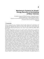
Therefore, as Fig.3 shows, comparing above three strategies, even system performance will
be increased during sequential, iterative, and simultaneous strategies, but
ID
DTC
DFC
: Finial state
: Initial state
Control cost
Fig. 3. Control cost in iterative process.
Integrated Mechatronic Design for Servo Mechanical Systems
115
3. Legged mechatronic system design
Most mobile robots are equipped with wheels. A wheel is easy to control and direct,
provides a stable base on which a robot can maneuver and is easy to construct. However,
one major drawbacks of a wheel is the limitation it imposes on the terrain the can be
successfully navigated. Therefore, research into legged locomotion is important as legs can
overpass rough terrain. Thus, create a leg mechanism that walks has becomes a central goal
in the field of robotics [13-15]. Based on this reason, in this study, the CARSI will be used in
rapid legged mechatronic system design process, and the flow chart shows in Fig. 4.
Matlab
System
Identification
Simulink
LTI
Control
ToolBox
Real-Time
Workshop
Real-Time
workshop
Embedded Coder
Embedded Target for
ICP_CON I-8438
Design and Simulation
Code Generation
CAD data
XML data
translate
Legged mechatronic
Fig. 4. Legged mechatronic system design flow chart.
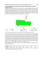
3.1 Legged structure
Basic considerations for a leg design for a walking machine are as follows: the leg should
generate an approximately straight-line trajectory for the foot with respect to the body; the
leg should have a simple mechanical design; and, when specifically required, it should have
the minimum number of DOFs to ensure motion capability. Therefore, the basic principle in
this study is to create a walking machine via the linkage method with symmetrical coupler
curves to combine the functions of a four-bar linkage and a pantograph into one leg
structure [16][17].
Based on the embedded-type leg mechanism (Fig. 5), an embedded trajectory P is first
designed via a four-bar linkage, and then magnified by a scale ratio n (B
0E=nB0D) to obtain
the gait profile G. Therefore, according to design specifications (Table 1), the parameters of
the embedded four-bar linkage are obtained. Moreover, all design processes are based on
the following assumptions:
1. No transmission loss exists between the input and end effect of this mechanism.
2. Ground reaction force on the end effect is constant.
Advances in Mechatronics
116
P
A
0
B0, B0'
D
E
G
C
F
Fig. 5. Legged structure.
3.2 Optimal multivariable design for gait profile
As discussed, gait profile can be designed using an embedded four-bar linkage, and
magnified using a pantograph to satisfy the target. Additionally, to decrease leg size (or
minimize scale ratio n) and obtain an enhanced footpath height, the design objective
function can be formulated as (3).
11
1
min ( ( ) ( ) )
sh
Ill
(3)
s.t.
1
12
2cos cos sin
00
000
12 14
2(2)
2
45 135
cm A B cm
cm A C CD A B cm
where:
,
: weighting factor,
=1,
=0.2
Integrated Mechatronic Design for Servo Mechanical Systems
117
s
l : stride length of the embedded four-bar linkage
h
l
: foot-path height of the embedded four-bar linkage
: skew angle
CDF
Table 2 lists optimal results based on (3) and those constrains. Additionally, Fig. 6 shows the
six-bar walking machine gait profile and the embedded four-bar linkage profile.
Parameters DTC DFC Var. %
Structure Parameters
00
AB (cm)
12.8
12.8 -
0
AC (cm)
2.6 2.6 -
0
BD= EF (cm)
8 8 -
0
BE= DF (cm)
30.8
30.8 -
Mass of
0
AC (kg)
0.050 0.080 60
Mass of
0
BD
(kg)
0.035 0.07 100
Mass of
0
BE (kg)
0.134 0.134 -
Mass of CDF (kg) 0.368 0.215 -41.5
Mass of EFG
(kg)
0.316 0.177 -44.0
r2(cm) /
2
(deg)
1.3 / 0 0 / 0 - / -
r3(cm) /
3
(deg)
16.0 / 35.6 14.6 / 38.0 -8.6 / 6.3
r4(cm) /
4
(deg)
4 / 0 0 / 0 - / -
r5(cm) /
5
(deg)
12.5 / 42.0 11.6 / 36.6 -7.5 / -13
r6(cm) /
6
(deg)
15.4 / 0 15.4 /0 - / -
(deg)
51.2
51.2 -
n 3.8 3.8 -
(deg)
128.8 128.8 -
Controller Parameters
p
K
4.3 3.5 -18.6
i
K
4000 4800 20
pp
K
150 180 20
Max
(N-m) without acc/dec
(0.5 step/s)
0.14
0.12 -10
Max
(N-m) without acc/dec
(2 step/s)
0.5
0.2 -60
Table 2. Integrated Design Results.
Advances in Mechatronics
118
4 5 6 7 8 9 10 11 12
5
5.5
6
X direction (cm)
Y
di
rec
ti
on
(
cm
)
Gait profile of embbed four bar linkage
0 5 10 15 20 25 30
55.5
56
56.5
57
57.5
58
58.5
59
59.5
60
G
a
it
pro
fil
e o
f
wa
lki
ng mac
hi
ne
X direction (cm)
Y direction (cm)
(a) Embedded (with skew angle) (b) End effect
Fig. 6. Gait profile.
3.3 Controller design
When kinematic design of the walking machine was complete, controller design was
considered. Therefore, to integrate and model the mechatronic system of a walking machine
in the design process, Lagrange’s equation, which formulated as (4), is applied to derive the
all parameters in this controller design process.
222
dK K P
dt
(4)
where
K is kinetic energy, P is potential energy, τ is control torque, and
2
is angle of the
input link. Fig. 7 presents the detailed parameters of a system dynamic for a walking
machine. Thus, the primary parameters
K and P can be expressed by (5) and (6), and control
torque
was re-formulated as (7).
6
22 2
2
11
()
22
iix i
y
ii
i
KmVVJ
(5)
22 2 2 3 2 2 3 3 3
( sin( ) ( sin sin( ))Pmr mL r
44 4 4 5 2 2 3 3 3 5 5 5
sin( ) ( sin sin( ) sin( )mr m L L r
66 6 6
sin( ))mr g
(6)
where
i
m is mass of each linkage;
ix
V and
i
y
V
are the velocity in the x and y direction,
respectively, for each linkage;
i
r is the length from the central mass to a reference point;
i
L is the characteristic length for each linkage;
i
is the angle of central mass for each
linkage;
g
is gravity;
0.5
22
336 36
2cosLLL LL
.
In the other hand, use of simple controllers, such as PD/PID controllers, for industrial
manipulators and servo system applications are well known which works on the basis of
position loop control. In this work, in order to improve tracking performance for velocity
and position simultaneously, the IP controller was employed in the velocity loop, and the P
Integrated Mechatronic Design for Servo Mechanical Systems
119
controller was used in the position loop. The equation of control power
can be formulated
in (7).
() ( )
i
pp
m
p
m
tK eK dtK
(7)
where
e
,
pp
K
p
K and
i
K
are position tracking error, position loop proportion gain, velocity
loop proportion gain, and velocity loop integration gain, respectively. Following the Integral
Time Absolute Error (ITAE) criteria, the design objective for the controller was written as
(8), where
and
are weight factors, and
=1 ,
=0.1, the results are listed in Table 2.
min( () ())
.()5
0
Itetdtt
st t Nm
e
(8)
X
Y
L2
L3'
L4
L5
L6
G (Xp,Yp)
A
0
C
D
B
0
F
E
2
4
6
3
5
L1
r2
r3
r4
r5
r6
3
2
4
6
SM2
SM3
SM4
SM6
SM5
L3
L5'
5
3
5
Fig. 7. Dynamic model of linkage for Leg system.
Advances in Mechatronics
120
4. System optimization using the Design For Control (DFC) approach
As Fig. 8 shows the DFC iterative process [5][6][23], if system performance is unsatisfactory,
design process is returned to structural domain. The structural modification process will go
out of used the single domain constrains, and overall system dynamic conditions will be
replaced with original conditions, and pass into control domain to acquire a new controller
solution. Hence, DFC is not only used a concurrent (parallel) integrated design process to
achieve system performance, but also to enhance the control requirements to easy control
system in the design approach.
Project objective
Performance test
End
Not Ok
Ok
Design For Control method
Mechanical
design
Controller
design
Fig. 8. Integrated design of mechatronic system using DFC.
Following use of the DFC concept and Lagrange’s equation, the aim of the design process is
to decrease potential and kinetic energy first during these interactive design processes.
Thus, modifying system parameters of the leg linkage for the walking machine must be
considered, and system performance is based on structural results (5) and (6) in tuning the
controller parameters (7) at the same time. Therefore, following (5) and (6), two methods can
be utilized to improve system performance, namely, variable input speed [18], which
reduces kinetic energy for (5), and mass redistribution [5-6], which decreases both terms (5)
and (6) simultaneously. Thus, the “complete force balancing” method based on mass
redistribution was applied to enhance system performance. Hence, the primary objective in
this interactive process can be formulated as (9).
Based on this objective, when (9) equals zero, the dynamic equation for legged mechatronic
can be re-formulated as (10). From this equation, the dynamic behavior for this mechatronic
leg can be also reduced to a simple equation, i.e., control power is only considered as kinetic
energy and near constant potential energy during this interactive control design process. As
mentioned earlier, the basic idea of the DFC approach is to spare control design effort and
improve real-time performance by providing a simple dynamic model through judicious
mechanical design. Consequently, key parameters of the internal moment,
i
,
i
r , and
i
m ,
were improved (Table 2). Additionally, Table 2 also lists optimal control gains.
Integrated Mechatronic Design for Servo Mechanical Systems
121
2
min
P
I
(9)
22
dK K
dt
(10)
4.1 Multi-domain graphical model integration
With the rapid developments in computer science over the last 20 years, computer-aided
engineering software, such as Pro/Engineer, Solidworks, Ansys and Matlab, have been
widely utilized in structure and control fields. Therefore, file format standards, such as the
Initial Graphics Exchange Specification (IGES), STEP (ISO-10303) and DXF, were developed
to address the incompatibility issue of various CAD/CAM systems. This standard allows
for efficient and accurate exchange of product definition data across almost all CAD/CAM
systems.
As each computer-aided engineering software package using a unique method of describing
geometry both mathematically and structurally, some information is always lost when
translating data from one system data format to another. Intermediate file formats are also
limited in what they can describe, and can be interpreted differently by both the sending
and receiving systems. When transferring data between systems, identifying what needs to
be translated is important. Additionally, translating intermediate files always focuses on the
same engineering domain. Therefore, in the mechatronic system, intermediate file formats
or parameters must be considered in detail to be accepted by each domain. That is,
modeling of different system domains in the same model is possible when the language
used for describing the model is extensible and includes several standard libraries for
different domains; this helps users because they can use modeling tools with which they are
familiar for different tasks.
XML (eXtensible Markup Language) is a World Wide Web Consortium (W3C)
recommended general-purpose markup language that supports a wide variety of
applications [19]. The XML language and its ‘dialects’ can be designed by anyone and can be
processed using appropriate software. Notably, XML is also designed to be reasonably
human-legible.
According to kinematic synthesis results for the leg linkage (Table 2), the 3D graphical
model for the mechatronic leg was first designed using Pro/E (Fig. 9(a)). Moreover, based
on the (4), (5), (6), parameters of linkages, such as mass, length, position, center of gravity,
unit, volume, and constrain (or joint type), were obtained from this CAD data. Following
this step, the graphical model, based on XML syntax, in reference to control requirement
parameters was obtained. According to this model and parameters (Table 2), the embedded
controller was also created using this graphical model (Fig. 9(b)).Consequently, to simplify
modeling and simulation for the mechatronic system in this study, a graphical environment
called CARSI technology was employed for structural design, controller design and
implementation in the same design environment.
Based on CARSI method, Fig. 10(a) and 10(b) present results obtained by the DTC and DFC
methods, respectively. Comparing the simulation results obtained with DTC and DFC, the
performance of the mechanism after applying the mass-redistribution scheme was
significantly improved; the maximum control torque at low and high speeds was reduced
by 10%, from
0.14N-m to
0.12 N-m and 10%, from
0.5N-m to
0.2 N-m, respectively.
Advances in Mechatronics
122
According to these analytical results, once the mass and mass center are fixed during
machine walking, the potential energy term will have almost no influence even when speed
is changed. Conversely, based on the DTC result, when walking speed changed, control
power increases.
Pro/E
SimMechanics
{
{
File information
Characteristics for
part
Fig. 9. (a) Multi-domain transforms
Integrated Mechatronic Design for Servo Mechanical Systems
123
Input Command
P-IP Controller
Legged mechatronic
(b) Simulation model of legged mechatronic.
Fig. 9. Multi-domain graphical model.
0 0.2 0.4 0.6 0.8 1 1.2 1.4 1.6 1.8 2
-1
-0.5
0
0.5
1
1.5
2
2.5
3
3.5
4
Time (s ec)
Control power (N-m)
2 step/s
0.5 step/s
Fig. 10. (a)
Advances in Mechatronics
124
0 0.2 0.4 0.6 0.8 1 1.2 1.4 1.6 1.8 2
-0.4
-0.2
0
0.2
0.4
0.6
0.8
1
Time (sec )
Control power (N-m)
2 step/s
0.5 step/s
(b)
Fig. 10. Control power for DTC and DFC methods.
5. Rapid control prototyping
As control systems become increasingly complex with the development of control
algorithms and controller designing techniques, manually interpreting and designing the
control system using differential equations or numerical formulas is time-consuming and
difficult. Additionally, various user-friendly graphs and interfaces are necessary as well as
complex computations, and, moreover, because repetitive operations on the same work is
mandatory when designing a control system, conventional handwork programming is not
an easy job and is inefficient when faced with increased pressure for reducing product time-
to-market.
Rather than conventional low-level programming languages, graphical model-based
programming has been used increasingly for real-time simulation and hardware-in-the-loop
(HIL) applications to obtain rapid prototyping of various electrical and mechanical systems.
Compared with conventional low-level handwork programming, the most important
feature of state-of-the-art control applications is the function that generates program codes
automatically through some user-friendly graphic modules to decrease the time required for
system development.
As mentioned, “Matlab/Simulink” software is a design and simulation tool used most in the
control field. This software allows users to create models for dynamic systems simply by
connecting blocks from given libraries, and also includes a library called SimMechanics,
which simulates rigid body dynamics using a 3D graphical model. Some blocks of
Integrated Mechatronic Design for Servo Mechanical Systems
125
Matlab/Simulink implement linear systems given as transfer functions or state-space
realizations both in continuous and discrete time. When a simulate is complete, the Real-
Time Workshop (RTW) toolbox generates C-code from the model without a need for
programming knowledge. Therefore, rapid controller prototyping techniques facilitate
implementation and validation of control strategies during the development process: users
can work within the same environment from structure requirement analysis to the controller
design and implementation phases. Based on this software, three implementation types are
supported by the RTW toolbox, namely, Real-Time Windows Target, xPC target, and Real-
Time Embedded Target. For the first two techniques, the target real-time devices are based
on PC. Therefore, real-time performance or space must be considered in detail [20].
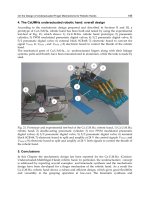
As previously stated, Figure 11 presents the “ICP_i8438” module, which is based on a
micro-chip and provides some add-on modules such as analogy output (I-8024) and encoder
feedback (I-8090) [21]. According to this model and legged mechatronic system (Fig. 12(a)),
the simulation and experimental results are shows in Fig. 12(b).
As these results, the constant friction torque from each joins was assumed at 0.3 N-m. The
experimental and simulation results are very close; however, one obvious problem with this
result is that dynamic friction during the acceleration phase was not considered. Restated,
integration of a graphical-based model and equation-based model to simulate a mechatronic
system can easily obtain, predict and modify system model parameters to achieve the goal
for a real system.
Fig. 11. Model for HIL.
Advances in Mechatronics
126
0 0.2 0.4 0.6 0.8 1 1.2 1.4 1.6 1.8 2
0
0.1
0.2
0.3
0.4
0.5
0.6
0.7
Tim e (s ec)
Control power (N-m)
EXP
SIM
(a) Legged mechatronic system (b) Results for experimentation and simulation
Fig. 12. Legged mechatronic.
6. Conclusion
An integrated design concept DFC and rapid implementation CARSI for a walking machine
are proposed in this paper. The DFC was utilized to design the mechanical structure of a
mechatronic leg system by fully exploring the physical characteristics of the overall system
while considering controller design and execution of control actions with the least
significant hardware restriction. Restated, DFC not only helped the mechatronic system
satisfy low driving power, its also helped easy to control the system. Additionally, the
CARSI approach achieved structural design, controller design and system implementation
simultaneously in the same design environment to reduce development time for the
mechatronic leg system.
7. References
[1] A.L. Hale, R.J. Lisowski, and W.E. Dahl, “Optimal simultaneous structural and control
design of maneuvering flexible spacecraft,” J. of Guidance Controller and Dynamics,
Vol. 8, No. 1, pp. 86-93, 1985.
[2]
D.S. Bodden and J.L. Junkins, “Eigenvalue optimization algorithms for
structure/controller design Iterations,” J. of Guidance Controller and Dynamics, Vol.
8, No. 6, pp. 697-706, 1985.
[3]
Messac, “Control-structure integrated design with closed-form design metrics using
Physical Programming,” AIAA Journal, Vol. 36, No. 5, pp. 855-864, 1998.
[4]
J.H. Park and H. Asada, “Concurrent design optimization of mechanical structure and
control for high speed robots,” ASME Journal of Dynamic System, Measurement, and
Control, Vol. 116, pp. 344-356, Sep. 1994.
[5]
F. X. Wu, W. J. Zhang, Q. Li, and P. R. Ouyang. “Integrated design and PD control of
High Speed Closed-loop Mechanisms,” ASME Journal of Dynamics System,
Measurement and Control, Vol. 124, No.4, pp. 522-527, 2002
Integrated Mechatronic Design for Servo Mechanical Systems
127
[6] Q. Li, and F. X. Wu, “Control Performance Improvement of a Parallel Robot via the
Design for Control Approach,” Mechatronics, vol.14, no.8, pp.947-964,
2004
[7]
A.C. Pil and H. Asada, “Integrated structure/control design of mechatronic system
using a recursive experimental optimization method,” IEEE/ASME Transactions on
Mechatronics, Vol. 1, No. 3, pp. 191-203, 1996.
[8]
K. Fu and J. K. Mills, “A Convex Approach Solving Simultaneous Mechanical Structure
and Control System Design Problems With Multiple Closed-loop Performance
Specifications,” ASME Journal of Dynamic Systems, Measurement, and Control, Vol.
127, pp.57-68, 2005.
[9]
Manfred Glesner, Andreas Kirschbaum, Frank-Michael Renner, and Burkart Voss,
“State-of-the-art in rapid prototyping for mechatronic systems,” Mechatronics, Vol.
12, No. 8, pp. 987-998, 2002
[10]
Roberto Bucher and Silvano Balemi, “Rapid controller prototyping with
Matlab/Simulink and Linux,” Control Eng Prac, Vol. 14, No. 2, pp. 185-192,
2006.
[11]
M. Deppe, M. Zanella, M. Robrecht and W. Hardt, “Rapid prototyping of real-time
control laws for complex mechatronic systems: a case study,” Journal of Systems and
Software, Vol. 70, No.3, pp. 263-274, 2004.
[12]
Chattopadhyay and N. Pagaldipti, “A multidisciplinary optimization using semi-
analytical sensitivity analysis procedure and multilevel decomposition,” Computers
Math. Applic., Vol. 29, No. 7, pp. 55-66, 1995.
[13]
Manuel, Pablo Gonzalez de Santos. Climbing and Walking Robots. Springer Berlin
Heidelberg, Germany, 2005.
[14]
M. O. Tokhi , M. A. Hossain and G. S.Virk “Climbing and Walking Robots,” Springer
Berlin Heidelberg, Germany, 2006.
[15]
Y. J. Chen, “Mechanism Design of An 8-link Type Biped Walking Machine with
Auxiliary Wheels,” Master thesis, National Cheng Kung Univ.,
2004
[16]
W. B. Shieh, L. W. Tsai and S. Azarm, “Design and Optimization of a One-Degree-of
Freedom Six-Bar Leg Mechanism for a Walking Machine,” Journal of Robotic System,
Vol. 14, No.12, pp. 871-880, 1997.
[17]
E. Ottaviano, C. Lanni and M. Ceccarelli, “Numerical and Experimental Analysis of a
Pantograph-Leg with a Fully-Rorative Actuating Mechanism,” Proc. of the 11
th
World Congress in Mechanism and Machine Science, Tianjin, China,
2004
[18]
H. S. Yan and R. C. Soong, “Kinematic and dynamic design of four-bar linkages by
links counterweighing with variable input speed,” Mech Mach Theory, Vol. 36, No.9,
pp. 1051-1071, 2001.
[19]
J. Yang, S. Han, J. Cho, B. Kim, H. Y. Lee, “An XML-based macro data representation
for a parametric CAD model exchange,” Computer-Aided Design and Applications,
Vol. 1, No. 1-4, pp. 153-162, 2004.
[20]
C. Sun, “The Integration of MATLAB and Embedded Controller for Control
Application,” Master thesis, National Sun Yat-Sen Univ., 2004
Advances in Mechatronics
128
[21] ICP DAS Co. User manual of I8438/8838 Matlab embedded control.
[22]
K. Craig, F. Stolfi, “Teaching control system design through mechatronics: academic
and industrial perspectives.” Mechatronics, Vol 12, No. 2, pp. 371-381, 2002.
[23]
Q. Li, W.J. Zhang and L. Chen, “Design for control-a concurrent engineering approach
for mechatronic systems design,” Mechatronics, IEEE/ASME Transactions on
Mechatronics, Vol. 6 , No. 2, pp. 161-169, 2001.
[24]
J, van Amerongen, “Mechatronic design”, Mechatronics, Vol. 13, No. 10, pp. 1045-1066,
2003.
[25]
K. Craig, “The role of computers in mechatronics”, Computing in Science & Engineering,
Vol. 5, No. 2, pp. 80-85, 2003.