Designing and Deploying RFID Applications Part 7 pptx
Bạn đang xem bản rút gọn của tài liệu. Xem và tải ngay bản đầy đủ của tài liệu tại đây (3.8 MB, 30 trang )
Designing and Deploying RFID Applications
168
works with the support of a knowledge management system which helps managers to
make decisions on scheduled logistics of waste to treatment plants and also provides the
instruction for the operating staff dealing with the plasterboard waste and also other kinds
such as medical waste etc. All the RFID fixed readers are associated with imagery
equipment, digital imagery could be automatically taken when a valid tag successfully
scanned by RFID reader. These digital imagery records will be well documented as the
evidence to verify the transportation.
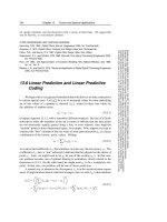
Figure 7 also illustrates the system of a ‘main construction demolition site’ and near ‘smaller
construction demolition site’ which are the two typical source sites. The plasterboard waste
is designed to be bagged in the source sites during the demolition/building process and a
RFID tag is then attached to the container (bag, box, or bins etc.) immediately.
Fig. 7. Frameworks for Plasterboard Waste Management System
Plasterboard waste can go directly to the landfill with mono-cell. If the construction or waste
company wishes to land fill them, the prototype system can fulfil the function of providing
the evidence by records and image. The RFID equipment and RFID reader is set on the
entrance of the landfill site to verify the arrival of the waste. When the containers pass this
gate, a record will automatically be created and uploaded to the central server to show the
logistics of the containers and the appropriate tonnages of plasterboard waste being
transported or delivered to recycling and/or landfill sites.
Hand-held devices are used by the operating staff involved in the system, including vehicle
drivers, cleaners, demolition operators and waste managers etc. The device is a small sensor
that links to the central server, and can display information from the system. The instruction
and logistical support information will be automatically downloaded from the knowledge
management system when it is required. The information notifies the operators which
container should be transported or moved to the correct location in a specific time, and also
Application of RFID and Mobile Technology to Plaster Board Waste in the Construction Industry
169
notifies the procedure of transporting this type of waste and any particular cautionary
instructions.
6.2 Knowledge hub design
The prototype system is designed using a knowledge hub as the back end support, which
includes a knowledge based system and reasoning to provide the logistical support for the
waste management. The reasoning system is designed using Rule-based Reasoning, and the
structure of the knowledge base is illustrated in Figure 8.
Figure 8 illustrates the structure of the knowledge hub system that is designed in four
layers. The lowest layer is the hardware layer, called Data processing layer, which is the
route for acquiring the data and information from the RFID and imagery equipment into the
system (Zhang et al., 2008). The data gained from the equipments are separately sent to data
bases, located in the second lowest layer.
The second lowest layer is the knowledge storage layer, called data integrate layer. This
layer contained two databases which stores the RFID data and imagery data from lower
layer, and another database is responsible for integrating the two types of information and
prepares them ready for the next layer usage. In fact, this database is a ‘fact’ storage that
used for the reasoning. In addition, the database can output ‘fact’ to a long term data storage
data warehouse, and an OLAP (Online Analytical Processing) function can introduced into
the system for better performance.
Fig. 8. 4-Layer Structure with Rule-Based Reasoning
The next higher layer is the core layer, which is called the knowledge reasoning layer. Rule-
based reasoning is the main reasoning mechanism for generating the best solution for
logistical and tracking support. The inference engine is the core of this layer that works
with the rule base and the fact uploaded from lower layers.
Designing and Deploying RFID Applications
170
The knowledge is stored in productive rule (IF…THEN…) format at the rule base. The three
components compose the full Rule Based Reasoning system. The result of this layer is a
suggestion solution’ that is generated by the previously inputted rules, the reasoning aspect
including the logistic suggestion and also the guidance for the waste operators, depending
on the users requirements. Finally, the result is then passed to the highest layer -
visualisation to provide the resolutions for decision support.
The highest layer bears the communication function between the system and users. This
layer is called visualisation layer, which is designed to represent the logistical solution and
the guidance in suitable client machine, either the desktop computer or hand held device.
The visualisation layer can be associated with web-based application to represent data for
easy access and flexible monitoring, and alternatively may use as individual programme to
improve the security and more trustable evidence. The visualisation layer is also
responsible for the user’s command input; the command will pass to the lowest layer
through the kernel module.
6.2.1 Adopting of rule-based reasoning
The rule-based system is usually called an expert system, and is the most popular choice for
knowledge-based applications. A simplified definition of rule based reasoning is a
technology in which knowledge is represented by a set of IF…THEN production rules and
data is represented by a set of facts(Giarratano and Riley, 2005). The rule will be executed
when the fact matches the condition of a rule, and it may add or modified to fact for a new
rule execution until the final result is determined(Giarratano and Riley, 2005).
Rule-based reasoning has some advantages compared with other reasoning technology and
has been generally accepted as the best option for a knowledge-based system. It typically
features natural knowledge representation, uniform structure, separation of knowledge
from its processing and has the ability to deal with incomplete and uncertain knowledge.
Some features of rule-based reasoning are suitable for the prototype system, and are
discussed as follows(Giarratano and Riley, 2005).
Rule-based reasoning technology stores knowledge in IF…THEN structure meaning each
piece of knowledge is relevantly independent from other knowledge. This structure is
efficient for finding out the target knowledge when the waste regulation is amended.
Secondly, the waste management system requires that knowledge should be easy to adopt
into the reasoning system without complex transformation. In fact, it is better to input
knowledge without any programme skills for ease of use and maintenance/updating
purposes.Individual knowledge storage is a key required feature that separates knowledge
from the system and thus it could be removed without affecting the system design and a
new knowledge base which contains the knowledge for other waste management areas
could be supplemented.
6.2.2 Optimization module design
The reasoning layer is responsible for the optimized schedule plan, generates the real time
guidance and reports on the current situation function, but the optimized schedule plan is
the major task of the knowledge reasoning layer.
Normally, schedules include two aspects: the time plan and the route plan. However,
considering the application is designed for a waste recycling company and most waste
collection times are contracted, therefore the prototype system only needs to generate the
Application of RFID and Mobile Technology to Plaster Board Waste in the Construction Industry
171
route plan and the time schedule has been assumed to be initially confirmed by contract
between the waste company and the construction company.
The routing plan of the transportation can be seen as a classic TSP (Travelling Salesman
Problem) question, which has the same requirement: the vehicle departs from the recycling
facility, visit each site one time, and finally returns to the recycling facility. The major task of
the reasoning layer is planning and finding an efficient route. It is also responsible for real-
time planning in case of an emergency where a new route needs to be planned.
The requirement of the prototype system’s application area restricts the route plan
algorithm to matching the following features: 1) Inherent parallelism, which needs to
consider more than one route at the same time 2) Efficient to solve TSP and similar
problems. 3) Can be used in dynamic applications. Therefore, for this application, ACO
(Ant Colony Optimization) will be introduced in the system that is responsible for
generating the route plan (Colorni et al., 1991, Dorigo and Gambardella, 1997, Dorigo et al.,
1999, Qiang and Qiuwen, 2008).
The ACO module is only dealing with the vehicle routing plan, therefore it needs to be
independent from the main rule-base to reduce complications, and thus it does not need to
be converted in production rule format. It only works when the vehicle type and target site
has been decided by the rule based reasoning system; the vehicle and site information will
be passed to the ACO module as the initial parameters, then the acceptable result can be
generated in limited iterations and this is illustrated in Figure 9.
Fig. 9. The 4-layer Structure with ACO Module
The work procedure of the reasoning layer starts from the time schedule and routing plan.
Firstly, the system will check the current time and query the database if there are any sites
which need to be visited in this time (day, week or month) and also query the last operation
Designing and Deploying RFID Applications
172
on that site to roughly estimate the tonnage of the waste. The estimating also takes into
account the site project, construction progress and even its financial situation.
The next step is to decide the vehicle type and the number. After the site which must be
visited in the next period has been decided and the waste tonnage of each site is estimated,
obviously the total amount of waste will be known. The vehicle type can then be decided
based on this information; the capacity of the vehicle should be larger than the tonnage and
depends on the containers used on the sites. The rule-based system will be based on these
‘facts’ to reason out the vehicle type and number. Planning the details of vehicle routing is
the function of the ACO, which firstly decides the routes to be calculated and the sites for a
single trip. Then the exact route will be calculated by the ACO, in the prototype of the waste
management system, only the original ACO will be introduced for evaluating purposes.
After the routing has been decided, the details will be passed to the visualization layer for
guidance.
Another important function of the prototype system is providing guidance to the operation
staff to help them deal with the waste. It works as a handbook to remind them when, where
and how to collect/transport the waste. The transport plan is part of the guidance
information that can give clear instruction about route choice and waste collect procedure to
the vehicle drivers.
7. Conclusions
This chapter introduced the current plasterboard disposal situation and addresses the
logistical problem which is a barrier to an increased recycling rate. In the UK only four
known recycling facilities are available, all of which are located in England, and two of them
in the London area. This situation has caused difficulties with transportation, and the
recycling fees are higher than landfill if the source site is far from the facility. A prototype
system for waste management is outlined which uses RFID technology for the main data
collection methods, and rule-based reasoning and Ant Colony Optimization for auditing/
tracking the plasterboard waste and detailing the reasoning system and optimization
methods. It also has the function to make a schedule plan and provide the guidance to the
operation staff to ensure that waste containers are transported to the correct locations. The
system can also handle emergency changes such as traffic hold-ups etc, as it will re-arrange
suitable routes that reduce potential loss. The structure of a waste management and work
process are introduced, including the four layer structure showing the reliance of RFID
technology for collecting logistical data and digital imaging equipments are used to give
further auditing evidence. The reasoning core in the third layer is responsible for generating
schedules and route plans and guidance, and the last layer delivers the results to the users.
Finally, the function of a prototype system for waste management was discussed which uses
RFID technology for the main data collection methods, and rule-based reasoning and Ant
Colony Optimization for auditing/ tracking the plasterboard waste movement.
8. References
atkins, A. S., Zhang, L. & Yu, H. (2008) Issues in Environmental Recycling of Plasterboard
Waste and Application of RFID and Knowledge Technology. International
Conference on Software, Knowledge, Information Management and Applications
Application of RFID and Mobile Technology to Plaster Board Waste in the Construction Industry
173
(SKIMA). March, Kathmandu, Nepal Co-sponsored by IEEE pp 54-59 ISBN
9781851432516.
Barber, G. & Tsibertzopoulos, E. (2005) An analysis of using EPCglobal class-1 generation-2
RFID technology for wireless asset management. Military Communications
Conference, 2005. MILCOM 2005. IEEE.
Bourn, M. (2005) Landfill Directive Regulatory Guidance Note 11. ENVIRONMENT
AGENCY.
Bradshaw, B. (2004) The Landfill (England and Wales) (Amendment) Regulations 2004.
Statutory Instrument 2004 No. 1375. Department for Environment, Food and Rural
Affairs.
Bradshaw, B. (2005) The Landfill (England and Wales) (Amendment) Regulations 2005.
DEFRA, Statutory Instrument 2005 No. 1640.
Chawla, V. & Dong Sam, H. (2007) An overview of passive RFID. Communications
Magazine, IEEE, 45, 11-17.
Colorni, A., Dorigo, M. & Maniezzo, V. (1991) Distributed optimization by ant clonies.
Proceedings of the 1st European Conference on Artificail Life, 8.
DEFRA (2006) Estimated Total Annual Waste Arising by Sector: 2004 Department for
Environment, Food and Rural Affairs, Available
from: />fg02.xls, Cited: 02-Oct-2007.
DEFRA (2007) Waste Strategy for England 2007. Department for Environment, Food and
Rural Affairs.
Dorigo, M., Di Caro, G. & Gambardella, L. M. (1999) Ant algorithms for discrete
optimization. Aritificial Life, 5, 137-172.
Dorigo, M. & Gambardella, L. M. (1997) Ant colony system: a cooperative learning approach
to the traveling salesman problem. Evolutionary Computation, IEEE Transactions
on, 1, 53-66.
EA (2007) Hazardous waste deposits in England & Wales 2005. Environment Agency,
ironment-
agency.gov.uk/commondata/103601/05_tables_240707_1787522.xls, Cited
11/July/2008.
EA (2008a) Hazardous waste deposits in England & Wales 2006. Environment Agency,
antaeth-yr-
amgylchedd.cymru.gov.uk/commondata/103601/ew_haz_waste_2006_1902503.xl
s ,Cited 11/July/2008.
EA (2008b) Position Statement MWRP 007. Environment Agency.
EUROPEAN_COUNCIL (2002) Establishing Criteria and Procedures for the Acceptance of
Waste at Landfills Pursuant to Article 16 of and Annex II to Directive 1999/31/EC.
COUNCIL DECISION 2003/33/EC. European Council
Giarratano, J. C. & Riley, G. (2005) Expert systems : principles and programming, Boston,
Thomson/Course Technology.
GRI (2011) "Gypsym Recycling International ". , Cited
28/Jan/2011.
Hamm, H., Huller, R. & Demmich, J. (2007) Recycling of plasterboard. Zkg International, 60,
68-74.
Heguy, D. & Bogner, J. (2004) Cost-Effective Hydrogen Sulfide Treatment Strategies for
Commercial Landfill Gas Recovery: Role of Increasing C&D (Construction and
Demolition) Waste. Municipal Soild Waste Management.
Designing and Deploying RFID Applications
174
Hirz, H. & Sterr, H. (1995) Recovery of components of waste plasterboard. IN PATENT, U.
S. (Ed. B02C 2318 ed., Gebruder Lodige Maschinenbangesellschaft mit,
beschrankter Haftung.
James, P. R., Pell, E., Sweeney, C. & John-Cox, C. S. (2006) Review of Plasterboard Material
Flows and Barriers to Greater Use of Recycled Plasterboard. The Waste &
Resources Action Programme.
John, S. & Knez, J. (1993) Method for recycling wallboard. B02C 2300 ed., Knez Building
Materials Company.
Kitsos, P. & Zhang, Y. (2008) RFID security : techniques, protocols and system-on-chip
design, New York ; London, Springer.
Kleist, R. A., Chapman, T. A., Sakai, D. A. & Jarvis, B. S. (2004) RFID Labeling-Smart
Labeling Concepts & Applications for the Consumer Packaged Goods Supply
Chain, Printronix.
Landt, J. (2005) The history of RFID. Potentials, IEEE, 24, 8-11.
Lehpamer, H. (2008) RFID design principles, Norwood, MA ; London, Artech House.
Lund-Nielsen, H. (2007) Experience in gypsum recycling on three continents. Global
Gypsum MAGAZINE. Surrey,UK, PRo Publications International Ltd.
Mcbean, E. A., Rovers, F. A. & Farquhar, G. J. (1995) Landfill Gas Collection and Recovery.
Solid Waste Landfill Engineering and Design. London, Prentice-Hall,Inc.
Miles, S. B., Sarma, S. E. & Williams, J. R. (2008) RFID technology and applications,
Cambridge, Cambridge University Press.
Min, Z., Wenfeng, L., Zhongyun, W., Bin, L. & Xia, R. (2007) A RFID-based Material
Tracking Information System. IEEE International Conference on Automation and
Logistics.
MTP (2007a) BNPB2 Plasterboard - Waste Management. The Market Transformation
Programme.
MTP (2007b) BNPB3 Plasterboard - Legislation and Policy Drivers. The Market
Transformation Programme.
Pal., S. K. & Shiu, S. C. K. (2004) Foundations of soft case-based reasoning, Hoboken, N.J.,
Wiley-Interscience.
PBRUK (2007) Estimated cost model for plasterboard waste. Plasterboard Recycling UK,
Available from: cited: 19-Sep-2007.
Qiang, Z. & Qiuwen, Z. (2008) An Improved Ant Colony Algorithm for the Logistics Vehicle
Scheduling Problem. Intelligent Information Technology Application, 2008. IITA
'08. Second International Symposium on.
Roussos, G. (2008) Networked RFID : systems, software and services, London, Springer.
SEPA (SCOTLAND) (2007) Waste Data Digest 7 - WDD7, 2005 and 2005/2006 data.
Scotland's Enviromental Regualtor and Adviser.
Tudahl, D. L. & Bush, G. R. (2000) Apparatus and method for recycling gypsum wallboard
IN PATENT, U. S. (Ed. B02C 1800 ed.
Turban, E., Aronson, J. E. & Liang, T P. (2005) Decision support systems and intelligent
systems, Upper Saddle River, NJ, Pearson/Prentice Hall.
Zhang, L., Atkins, A. S. & YU, H. (2008) Application of RFID Technology and Knowledge
Hub for Logistic Support in Scrapped Type Recycling. 9th Informatics Workshop
for Research Students. June, Bradford UK, pp.190-195, ISBN 978 1 85143 251 6.
11
RFID-Based Equipment Monitoring System
Mohd Helmy Abd Wahab, Herdawatie Abdul Kadir, Zarina Tukiran,
Nor’aisah Sudin, Mohd Hafiz A. Jalil and Ayob Johari
Universiti Tun Hussein Onn Malaysia
Malaysia
1. Introduction
Automated monitoring systems are becoming trends, creating easier method to identify
item, tracking, monitoring and add on security values. In places where there are lots of
items accessed by many users, the tendency of loss is high due to weakness in items
monitoring. Here, we briefly describe our research on the university’s laboratory
perspectives. The main aim of the research is to work out a generic approach of monitoring
items in a place with several rooms. For example, there are laboratories with expensive
equipments are available in a university to support teaching and learning session.
Conventional approach of checking items for every session is difficult for lab administrator
as most libraries are being used by more than 20 students per session.These leads to a
challenge for lab administrator to monitor the flow of these items are always in place.
Currently, the monitoring of laboratory equipments is performed manually by the lab
administrator during each laboratory sessions. For every loan of equipment, a log book
needs to be filled up in order to keep track the transaction information.This system was
found to have a lot of weaknesses such as misuse of the equipment log records, losses of
equipment, no in-out transaction record and misplace of equipments. To automate the
process, Radio Frequency Identification (RFID) is identified as one of the most practical and
applicable in real time implementation in-line with the nature where most of the systems are
made computerized. In this paper, a solution has been provided for the problem
encountered in laboratory equipment monitoring system using RFID technology. Therefore
RFID-based monitoring system has been designed and developed to solve the problem
associated with the handling of laboratory equipments. This chapter is organised as follows.
Section 2 describes related works on RFID-based monitoring system. The architecture of the
system is mentioned in section 3. Application scenario and the implementation are briefly
explained in section 4 and 5 respectively. Finally, the chapter is concluded in Chapter 6.
2. Related work on RFID in monitoring
RFID is a wireless automatic identification that is gaining attention and is considered by
some to emerge as one of the pervasive computing technologies in history (Roberts, 2006).
As the technology grows very rapidly, RFID has received considerable worldwide attention
and widely used in monitoring and tracking ranging from human identification to product
Designing and Deploying RFID Applications
176
identification. Previous research has successfully indicated that RFID has been increasingly
expanded in various fields such as retail supply chain, asset tracking, postal and courier
services, education, construction industry, medical, and etc.
The work presented by Tan and Chang (2010) who had developed an RFID-based e-
restaurant system to change the traditional restaurant services which is considered as
passive. The utilization of RFID is to improve the service quality which is customer-centered
that enable waiters to immediately identify customers via their own RFID-based
membership card. It can also provide customized services such as enhanced dining table
service; pay the bills, instant transmission of customer orders to kitchens and flexibility of
managing payments of bills and discounts. However, in Ngai et. al. (2008), designed and
developed RFID-based sushi management system to help a conveyor belt sushi restaurant to
achieve better inventory control, responsive replenishment, and food safety control, as well
as to improve its quality of service.
In the perspective of animal tracking or livestock monitoring management system, Vouldimos
et. al. (2010) developed FARMA project which combined with RFID technology and mobile
wireless networking to track animal and the data in repository which contains animal data
records. The purposes of the system are to identify animal in case it gets lost and identify some
basic information about particular animals. A similar work done by Nor Suryani Bakeri et. al.
(2007) and Ahmad Rafiq Adenan et. al. (2006) developed a livestock monitoring system using
RFID. An RFID tag is used and attached to each livestock to monitor its movement in and out
as well as the basic information about any particular animals.
The use of RFID also could assist in customs clearance process by reducing the delay time.
According to Hsu, Shih and Wang (2009), the use of RFID can improve the efficiency of
cargo process, and reduce the inventory and labor cost. The work presented based on the
mathematical model of the customs clearance process-delay and the network of customs
delay is reconstructed based on the use of RFID. RFID also has been successfully applied in
global postal and courier services in monitoring the parcel delivery. One of the well known
courier service company is DHL which has been using RFID in their services since 1988 and
carried out 20 trials on active and passive technology and successfully proved it improved
the service and reduce the costs (EPC Global, 2005). The application of RFID in global
market in postal and courier services contribute 650 billion per year and Europe was the
leader in utilizing RFID in postal and courier services (Zhang, et. al., 2006).
High quality service lead to customer satisfaction, increase market share, and enhance
profitability of service organizations (Hoffman and Bateson, 1997). Oztaysi, Baysan, and
Akpinar (2009) have done a study to investigate the possibility of using RFID as a tool for
improving service quality in hospitality industry and primarily concern in tourism industry.
In monitoring of asset tracking, an effective and efficient managing the tracking of medical-
assets in healthcare facilities can be performed by the means of RFID. Oztekin et. al. (2010)
has done a study using enhanced maximal covering location problem along with critical
index analysis metric to optimize the design of a medical-asset tracking system constrained
by a limited number of RFID readers. Results indicate that the proposed technique has
improved by 72% compared to the currently utilized expert placement strategy.
Yan and Lee (2009) developed RFID application in Cold Chain monitoring system to track
the cold-chain product flowing in supply chain, ensure the products’ quality and comply
with relevant provisions during transportation. The system executes in real-time
environment and can track the location and monitor the temperature of cold-chain products
to ensure the quality. However, according to Loebbecke (2005) has done a research
RFID-Based Equipment Monitoring System
177
regarding the application of RFID in retail supply chain at a brink-and-mortar supermarket
to investigate the advantages and challenges with the early RFID applications in terms of
technological issue such as standardization, challenges on the data, network and application
layers.
Haron, et. al. (2010), designed and developed of a context aware notification system for
university students using RFID. The system aims to deliver urgent notifications to the
intended students immediately at their respective locations. A quite similar work done by
Herdawatie et. al. (2010) which integrates RFID and biometric sensor to track students in a
boarding school of their location at the selected restricted area.
As summary, based on the successful of RFID applications in various fields as discussed
above, it shows that its application is endless. This section onwards explains the RFID
application in tracking of laboratory equipments movement to ensure its availability. It also
aims at helping the lab administrator in monitoring the equipment from lost or misplaced.
The monitoring of equipments movement is not only being monitored by the lab
administrator but also by the top management through online databases.
3. System architecture
Building an automated tracking applications by integrating web services guarantee many
benefits, such as reduce clerical task and ease the management burden. The RFID-based
Equipment Tracking System is an integrated system that offers an effective solution of
managing items especially for large scale environment. It combines the RFID technology
and security devices to ensure the items are always been monitored and secured. The
system enable the university to give admission to selected individual to access locations,
permit movement of items, record the important data and also enable the viewing of record
via internet.
A faculty usually has a number of laboratories. Faculties with technical courses such as
Information Technology and Engineering usually have more laboratories. To implement the
system, an appropriate design is required to make sure it is suitable for the number of
laboratories and equipments in all laboratories. In this study, the design of the system which
utilizes RFID is divided into two; hardware design and software design as shown in the
architecture diagram in Figure 1.
There are six important components involved as illustrated in Fig. 1, (1) RFID Tag, (2) RFID
Reader, (3) Personal Computer, (4) RS232 Cable, and (5) LAN HUB and 6) CCTV Camera
The master server contains the database which is used to store all data collected from RFID
reader where user can read or change information in the database. The RFID tags contain
antennas to enable the receiving and transferring data. The passive RFID tag creates power
from magnetic field and use it to energize the circuits of the RFID chip and sends
information back to the reader in the form of radio-frequency waves. The physical layer of
the system is depicted in Figure 2. It shows how the computers and the master server are
connected. The software involved in developing the system is also outlined.
In the system, RFID technology were implemented to enable data to be automatically
recorded where each tag is embedded in the metric card (working pass) for individual and
attached to each equipments. The lab administrator will grant an access to selected
individual to enter a laboratory and also enable selected individual to move items out from
the lab and within the organization. Upon the individual is found attempt to force the
process the camera is triggered and activated to document the image of intended person and
buzz the alarm system and notify the person-in-charge.
Designing and Deploying RFID Applications
178
Fig. 1. System Architecture
Fig. 2. Physical layer of the system
RFID-Based Equipment Monitoring System
179
4. Application scenarios
The developed prototype is an online laboratory monitoring system that has three purposes;
which typically composed of (1) Laboratory grant access (2) Inventory control, and (3)
Online data viewing. The prototype has been applied at the UTHM research project lab. To
illustrate the concept, a sample of layout of application was provided in Figure 3.
Fig. 3. Application scenario layout
In the system, RFID tag is attached to both users and equipments. The RFID reader is
located at each Laboratory to record and verify the RFID tags in the area. Each laboratory is
equipped with a surveillance camera and an alarm indicator to deal with unforeseen
circumstance events. The recorded data is stored and managed by a central computer
whereby each laboratory computer is connected via intranet connection to ease any
information received from computer lab can be easily transmitted to central computer. The
main purpose of data, which is stored at the central computer, is to ease the management to
have a look the whereabouts of equipment and record of in-out information. The
administrator will grant the personal level access, equipment status and also permit online
monitoring to authorize individual.
Legally attempt to enter a laboratory with authorize RFID identification (id), lead the
magnetic door to unlock (door open) and record the entry information. Illegally attempt to
access the laboratory, the door keep locked and activate the camera and warning sign is
indicated to the system.Once the system detects a forceful behavior such as shaking the
door, the system triggers an alarm to notify the security. In side of inventory control,
intended user must be registered with authorized id before granted to move or lend the
equipments, once verified, magnetic door will unlock and information is recorded.
Otherwise, the registered id requires re-verification.
Designing and Deploying RFID Applications
180
5. Implementation
As mentioned in previous section, the RFID-based Equipment Monitoring System is used to
keep track the record on laboratory equipment. Hence, the laboratory, its equipments and
users who use the equipment in the laboratory need to be part of the system entities. This
can be done by enrolling these entities in the system.
Fig. 4. Access laboratories and equipments flowchart
At this moment, only three (3) laboratories have used the system and only authorised
personnel are allowed to access the labs. In order to ensure only the authorised user login to
the labs, they need to present their RFID card. Each laboratory is equipped with magnetic
door. Therefore, the RFID card acts as a key to unlock the magnetic door. All equipments
placed in the labs are tagged with RFID and registered in the system. This equipment can be
used and borrowed by the user either in the same laboratory or in other laboratories. For the
latter the user’s RFID card and the equipment’s tag should be readable by the RFID reader.
RFID-Based Equipment Monitoring System
181
Once the information is successfully matched by the system, the magnetic door will be
unlocked. Otherwise, the door remain locked if only the reader able to read equipment’s
information but not the user’s information. Figure 4 illustrates the flow to access laboratories
and equipments.
Fig. 5. The main GUI of RFID-based Equipment Tracking System
Fig. 6. The system flow of data management module
Designing and Deploying RFID Applications
182
The system has two main purposes; first is to register user, equipment and laboratories to be
part of the system entities. This is done by the system administrator through data
management module. The second is to keep track the equipment and to monitor the
activities of the user. The latter can be accessed through monitoring module. These two
main purposes are presented in the form of graphical user interface as shown in Figure 5.
The data management module system flow is illustrated in figure 6. This module can only
be accessed by authorised personnel to maintain the integrity of the data. Thus, system
administrator needs to enter the correct password in login page as shown in Figure 7. Users
are allowed to re-enter the password up to three (3) times for invalid password before the
system activates the alarm system.
(a) (b)
Fig. 7. System administrator’s (a) entering the password and (b) warning message for
invalid access
Fig. 8. Data Management Module
RFID-Based Equipment Monitoring System
183
Fig. 9. Authorised user
Fig. 10. The system flow of data monitoring module
Designing and Deploying RFID Applications
184
Then system administrator is able to view the data if the administrator is the authorized
personnel. The data management module handles four (4) sub-modules which are described
as Figure 8. According to Figure 8, Equipment sub module allows the system administrator
to add new equipment and maintain the equipment record that is assigned in the laboratory.
RFID tag is attached on the equipment to track down its status. Lab sub module allows the
system administrator to enroll any laboratory to the system. User sub module allows the
system administrator to enrol any user that wants to be in the system. After the user has
been registered in the system, each will be given an RFID card. This card is used to authorise
access the intended laboratory. The user needs to bring along the card to enter or to leave
the laboratory. If user brings in/out any equipment to/from its registered laboratory, the
card and the equipment’s tag should be read by the RFID reader without fail in order to
unlock the magnetic door. Figure 9 shows an example of successful login to laboratory.
On-loan equipment sub module allows the system administrator to register the status of
equipment; whether it is in place or it is circulated around laboratory under an authorised
user.
The system flow of monitoring module is shown in Figure 10. The module allows the
administrator to monitor on-loan equipment, users’ activity and their status. This module is
designed so that it can be viewed by the administrator internally (intranet access) or
remotely (internet access). Here, the discussion is focused on remote access. In order to use
this module either internally or remotely, the administrator needs to log-in to the system as
shown in Figure 11.
Fig. 11. The login page of system
RFID-Based Equipment Monitoring System
185
Fig. 12. On-loan equipment page
Fig. 13. Monitoring user’s activity remotely
Designing and Deploying RFID Applications
186
For successful login, the administrator is allowed to view and find a specific record on on-
loan equipment. Figure 12 shows on-loan equipment based on laboratory and specific date.
As shown below, the following on-loan information is taken from instrumentation lab for
Jan 5, 2011. The system is also designed so that the administrator could click on Equip ID to
view equipment details borrowed by the user.
Figure 13 shows that the administrator is able to view user’s activity at each laboratory. In
the following example, it shows who has used the instrumentation lab on Jan 5, 2011. The
user status tab contains information on which laboratory is allowed and the valid period as
shown in Figure 14. By default, this page displays the status of all users. It also could
display the status of certain user by selecting specific information, for instance UserID
keyword to perform the searching process.
Fig. 14. Viewing user’s status
6. Conclusion
Laboratory equipment monitoring system using RFID is proposed to effectively monitor the
in-out equipment from the laboratory. Via this system, every activity involving laboratory
equipment can be monitored and updated through web based environment. For security
purpose, only authorized personnel have the permit to monitor the transaction activities of
laboratory equipment in real-time. The adaptation of RFID-based Equipment Monitoring
System also would promote diversity on laboratory management which previously are
handled manually.
RFID-Based Equipment Monitoring System
187
7. References
Ahmad Rafiq Adenan, Siti Zarina Mohd Muji, Mohd Helmy Abd Wahab. Automated
Animal Tracking System using Radio Frequency Identification Tags. Proceeding of
Computer Science and Mathematics Symposium 2006. KUSTEM, Kuala
Terengganu, Terengganu, Malaysia, 8 – 9 November 2006
EPC Global. RFID smart label practice experience. (2005-08-07) [2006-04-04],
di nfo.com. cn/report/dissertation/2OoS08/1655.html
Haron, N. S., Saleem, N. S., Hassan, M. H., Ariffin, M. M. and Aziz, I. A. A RID-based
Campus Context-Aware Notification System. Journal of Computing. Vol. 2. Issue 3.
Herdawatie Abdul Kadir, Mohd Helmy Abd Wahab, Zarina Tukiran Mohd Razali Mohd
Tomari and Mohd Norzali Hj. Mohd. (2010). Fusion of Radio Frequency
Identification (RFID) and Fingerprint in Boarding School Monitoring System
(BoSs), Sustainable Radio Frequency Identification Solutions, Cristina Turcu (Ed.),
ISBN: 978-953-7619-74-9, InTech, Available from:
/>identification-rfid-and-fingerprint-in-boarding-school-monitoring-system-b
Hsu, C-I, Shih, H-H, Wang, W-C. (2009). Applying RFID to Reduce Delay in Import Cargo
Customs Clearance Process. Computers & Industrial Engineering. Vol. 57. pp. 506 –
519.
Loebbecke, C. (2005). RFID Technology and Applications in Retail Supply Chain: The Early
Metro Group Pilot. 18
th
Bled eConference on eIntegration in Action, June 6 – 8,
2005, Bled, Slovenia.
Ngai, E. W. T. and Lo, S. Y. Y. (2008). Development of an RFID-based sushi management
system: The case of a conveyor-belt sushi restaurant. International Journal of
Production Economics, Vol. 112, Issue 2, pp. 630-645.
Nor Suryani Bakery, Ayob Johari, Mohd Helmy Abd Wahab, Danial, Md. Nor. RFID
Application in Farming Management System. In Proceeding of 3
rd
International
Conference on Robotics, Vision, Information and Signal Processing 2007
(ROVISP2007), Penang, 28 – 30 November 2007
Oztekin, A., Pajouh, F. M., Delen, D., and Swim, L. K. (2010). An RFID Network Design
Methodology for Asset Tracking in Healthcare. Decision Support Systems. Vol. 49,
pp. 100 – 109.
Oztaysi, B., Baysan, S., and Akpinar, F. (2009). Radio Frequency Identify (RFID) in
hospitality. Technovation. Vol. 29. Pp. 618 – 624.
Robert, C. M. (2006). Radio Frequency Identification (RFID). Computers & Security, Vol. 25.
Pp. 18 – 26.
Tan, T-H, Chang, C-S. (2010). Development and Evaluation of an RFID-based e-Restaurant
System for Customer Centric Service. Expert System with Applications. Vol. 37
Issue 9.
Voulodimos, A. S., Patrizakis, C. Z., Sideridis, A. B., Ntafis, V. A., and Xylouri, E. M. (2010).
A Complete Farm Management System based on Animal Identification using RFID
Technology. Computers and Electronics in Agriculture. Vol. 70. Pp. 380 – 388.
Yan, B. and Lee, D. (2009). Application of RFID in Cold Chain Temperature Monitoring
System. 2009 ISECS International Colloqium on Computing, Communication,
Control, and Management. Aug. 8 – 9, 2009. Sanya, China.
Designing and Deploying RFID Applications
188
Zhang, X., Yue, S., and Wang, W. (2006). The Review of RFID Applications in Global Postal
and Courier. The Journal of China Universities of Post and Telecommunications.
Vol. 13. Issue. 4.
12
Developing RFID-Based Instruments
Maintenance Management in Construction Lab
Yu-Cheng Lin, Weng-Fong Cheung, Yi-Chuan Hsieh,
Fu-Cih Siao and Yu-Chih Su
National Taipei University of Technology/ Civil Engineering
Taiwan
1. Introduction
Maintenance management is very important subject special in construction lab. To manage
related information of equipments and instruments plays an important role in the view of
construction lab management. Those equipments and instruments need high standard and
requirement in precision and accuracy of tests. Managing maintenance work effectively is
extremely difficult in construction lab owing to various equipments and instruments with
different specification. Furthermore, it will take high cost to maintain those instruments in
the good conditions for the test correctness. With the advent of the Internet, web-based
information management solutions enable information dissemination and information
sharing among related maintenance staff members. Generally, maintenance managers and
staffs require access to the equipments and instruments location to handle inspection and
maintenance work in construction lab. Usually, maintenance staffs generally use sheets of
paper to handle various types of maintenance information, including checklists,
specification, and maintenance procedure. Consequently, there is serious rework progress
regarding the data capture and entry in maintenance progress. In order to enhance the
effectiveness of inspection and maintenance work in construction lab, this study presents a
novel system called Mobile RFID-based Maintenance Management (M-RFIDMM) system for
the acquisition and tracing of lab equipments and instruments maintenance information on
locations and providing an equipments and instruments maintains information sharing
platform among all participants using web technology and RFID-enabled PDAs. Integrating
promising information technologies such as RFID-enabled PDAs, Radio Frequency
Identification (RFID) scanning and data entry mechanisms, can help improve the
effectiveness and convenience of information flow in the maintenance management. The
primary objectives of this study include (1) applying such a system that integrates RFID
technology with RFID-enabled PDAs to increase the efficiency of equipments and
instruments inspection and maintenance data collection, and (2) designing a web-based
portal for equipments and instruments management and control, providing real-time
information and wireless communication between offices and instruments locations. The M-
RFIDMM is then applied in a construction lab in Taiwan to verify our proposed
methodology and demonstrate the effectiveness of maintenance progress in construction
lab. The combined results demonstrate that, an M-RFIDMM system can be a useful web-
based lab maintenance management platform by utilizing the RFID approach and web
Designing and Deploying RFID Applications
190
technology. With appropriate modifications, the M-RFIDMM system can be utilized at any
instruments inspection and maintenance service for maintenance management divisions or
suppliers in support of the M-RFIDMM system.
2. Problem statement
Maintenance management performance can be enhanced by using web technology for
information sharing and communication. Information acquisition problems in instruments
management follow from most of the data and information being gathered from the
instruments location in construction lab. The effectiveness of information and data
acquisition influences the efficiency of maintenance execution. Usually, maintenance
managers and staff members generally use sheets of paper and/or field notes for
maintenance progress in Taiwan construction lab. Restated, existing means of processing
information and accumulating data are not only time-consuming and ineffective, but also
compromise maintenance management in information acquisition. Such means of
communicating information between instruments location and office, and among all
participants, are ineffective and inconvenient. According to the questionnaire survey, the
primary problems in inspection and maintenance regarding to data capture and sharing are
as follows: (1) the efficiency and quality are low, especially in the inspection and
maintenance progress in instruments management through document-based media, and (2)
there are serious rework progress regarding the data capture and input in inspection and
maintenance progress. However, few suitable platforms are developed to assist
maintenance staff members with capturing and sharing the inspection and maintenance
information when maintenance staff members need to handle inspection and maintenance
work. Therefore, to capture data effective and enhance information communication in
construction lab will be primary and significant challenge in the study.
3. Research objectives
This study utilizes the RFID and web technology to enhance the maintenance progress and
effectiveness in instruments management service. This system is controlled by the
management division, and provides maintenance managers and maintenance staff members
with real-time instruments-related information-sharing services, enabling them to
dynamically respond to the entire maintenance management network. This study develops
Mobile RFID-based maintenance management (M-RFIDMM) system to improve efficiency
and cost-effectiveness of instruments management, improve practical communication
among participants, and increase flexibility in terms of service delivery and response times.
M-RFIDMM system is a web-based system for effectively integrating maintenance
managers, maintenance staff members and relative members, to enhance the instruments
maintenance management in the construction lab. PDAs can extend M-RFIDMM systems
from offices to instruments locations. Data collection efficiency can also be enhanced using
RFID-enabled PDAs to enter and edit data on the instruments location. By using web
technology and mobile devices, the M-RFIDMM system for the management division has
tremendous potential to increase the efficiency and effectiveness of information flow, thus
streamlining services processes with other participants. Maintenance managers and staff
members frequently waste time by travelling to obtain information in the absence of other
efficient means of communication. The portal and PDAs enable maintenance staff members
Developing RFID-Based Instruments Maintenance Management in Construction Lab
191
to update data from the instruments location and immediately upload it to the system;
Maintenance managers can receive maintenance information and make better decisions
regarding future instruments management and control.
The main purposes of this study include (1) developing a framework for a mobile
maintenance management system for instruments in the lab; (2) applying such a system that
integrates RFID technology with PDA technology to increase the efficiency of instruments
inspection and maintenance data collection in the lab; (3) designing a web-based portal for
maintenance management and control, providing real-time information and wireless
communication between offices and instruments locations, and (4) Evaluating the
effectiveness of the proposed system in construction lab. Figure 1 illustrates solutions used
in a real case utilized M-RFIDMM system in Taiwan construction lab. With appropriate
modifications, the M-RFIDMM system can be utilized at any instruments inspection and
maintenance service for maintenance management divisions or managers in support of the
M-RFIDMM system.
Fig. 1. M-RFIDMM System Framework Overview
4. Background research
RFID is an automatic identification solution that streamlines identification and data
acquisition, operating similarly to bar codes. Automatic identification procedures have
recently become very popular in numerous service industries for purchasing and
distribution logistics, and in manufacturing companies and material flow systems. Jaselskis
and Anderson (1995) investigated the applications and limitations of RFID technology in the
construction industry, and attached read/write RFID tags to the surfaces of concrete test
that were cast from the job site to test lab. This RFID technology has been widely applied in
many areas in the construction industries for the following reasons: (1) to provide owners
and contractors with information to enhance operation using RFID technology (Jaselskis and