Vibration Analysis and Control New Trends and Developments Part 5 pot
Bạn đang xem bản rút gọn của tài liệu. Xem và tải ngay bản đầy đủ của tài liệu tại đây (2 MB, 25 trang )
Vibration Analysis and Control – New Trends and Developments
90
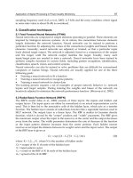
Fig. 15. Root locus of the total transfer function G
T
for CAFC on the footbridge. (×) pole; (ο)
zero; (F) footbridge; (A) actuator
−λ
A
F
F
Active Control of Human-Induced Vibrations Using a Proof-Mass Actuator
91
Uncontrolled
(m/s
2
)
Controlled
(m/s
2
)
Reduction
(%)
Mass displacement
(m)
Walking at 1.75 Hz 0.39 0.04 89
± 0.034
Running at 3.50 Hz 6.16 3.75 40
± 0.022
Table 3. Simulation performance assessment for the footbridge using the peak acceleration
for walking and running excitation
Walking and running tests are carried out to assess the efficacy of the AVC system. The
walking tests consist of walking at 1.75 Hz such that the first vibration mode of the structure
(3.5 Hz) could be excited by the second harmonic of walking. A frequency of 3.5 Hz is used
for the running tests so that the structure is excited by the first harmonic of running. The
walking/running tests consisted of walking/running from one end of Span 2 to the other
and back again. The pacing frequency is controlled using a metronome set to 105 beats per
minute (bpm) for 1.75 Hz and to 210 bpm for 3.5 Hz. Each test is repeated three times.
Uncontrolled Controlled Reduction (%)
Walking at 1.75 Hz
Peak acceleration (m/s
2
) 0.41 0.16 70
MTVV
(1)
(m/s
2
) 0.21 0.06 67
Running at 3.50 Hz
Peak acceleration (m/s
2
) 3.34 1.19 64
MTVV (m/s
2
) 2.20 0.69 68
Table 4. Experimental performance assessment for walking and running excitation.
(1)
Maximum Transient Vibration value defined as the maximum value of 1s running RMS
acceleration
The results are compared by means of the maximum peak acceleration and the MTVV
computed from the 1 s running RMS acceleration. Table 4 shows the result obtained for the
uncontrolled and controlled case. It is observed that the AMD designed (with a moving
mass of 30 kg) performs well for both excitations, achieving reductions of approximately 70
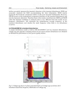
%. Fig. 16 shows the response time histories (including the 1 s RMS) uncontrolled and
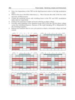
controlled for a walking test. Fig. 17 shows the same plots for a running test.
Vibration Analysis and Control – New Trends and Developments
92
Fig. 16. Walking test on the footbridge. a) Uncontrolled
2
MTVV 0.207 m s= . b) Controlled
2
MTVV 0.067 m s=
a)
b)
Active Control of Human-Induced Vibrations Using a Proof-Mass Actuator
93
Fig. 17. Running test on the footbridge. a) Uncontrolled
2
MTVV 2.198 m s= . b) Controlled
2
MTVV 0.773 m s=
a
)
b
)
Vibration Analysis and Control – New Trends and Developments
94
6. Conclusion
The active cancellation of human-induced vibrations has been considered in this chapter.
Even velocity feedback has been used previously for controlling human-induced vibrations,
it has been shown that this is not a desirable solution when the actuator dynamics influence
the structure dynamics. Instead of using velocity feedback, here, it is used a control scheme
base on the feedback of the acceleration (which is the actual measured output) and the use
of a first-order compensator (phase-lag network) conveniently designed in order to achieve
significant relative stability and damping. Note that the compensator could be equivalent to
an integrator circuit leading to velocity feedback, depending on the interaction between
actuator and structure dynamics. Moreover, the control scheme is completed by a phase-
lead network to avoid stroke saturation due to low-frequency components of excitations and
a nonlinear element to account for actuator overloading. An AVC system based on this
control scheme and using a commercial inertial actuator has been tested on two in-service
structures, an office floor and a footbridge.
The floor structure has a vibration mode at 6.4 Hz which is the most likely to be excited. This
mode has a damping ratio of 3% and a modal mass of approximately 20 tonnes. Reductions
of approximately 60 % have been observed in MTVV and cumulative VDV for controlled
walking tests. For in-service whole-day monitoring, the amount of time that an R-factor of 4
is exceeded, which is a commonly used vibration limit for high quality office floor, is
reduced by over 97 %. The footbridge has a vibration mode at 3.5 Hz which is the most
likely to be excited. This mode has a damping ratio of 0.7 % and a modal mass of
approximately 18 tonnes. Reductions close to 70 % in term of the MTVV has been achieved
for walking and running tests.
It has been shown that AVC could be a realistic and reasonable solution for flexible
lightweight civil engineering structures such as light-weight floor structure or lively
footbridges. In these cases, in which low control forces are required (as compared with other
civil engineering applications such as high-rise buildings or long-span bridges), electrical
actuators can be employed. These actuators present advantages with respect to hydraulic
ones such as lower cost, maintenance and level of noise. However, AVC systems for human-
induced vibrations needs much further research and development to jump into building and
construction technologies considered by designers. With respect to passive systems, such as
TMDs, cost is still the mayor disadvantage. However, it is expected that this technology will
become less expensive and more reasonable in the near future. Research projects involving
the development of new affordable and compact actuators for human-induced vibration
control are currently on the go (Research Grant EP/H009825/1, 2010).
7. Acknowledgment
The author would like to acknowledge the financial support of Universidad de
Castilla-La Mancha (PL20112170) and Junta de Comunidades de Castilla-La Mancha
(PPII11-0189-9979. The author would like to thank his colleagues Dr. Paul Reynolds and Dr
Donald Nyawako from the University of Sheffield, and Mr Carlos Casado and Mr Jesús de
Sebastián from CARTIF Centro Tecnológico for their collaboration in works presented in
this chapter.
Active Control of Human-Induced Vibrations Using a Proof-Mass Actuator
95
8. References
APS. Instruction Manual Electro-Seis Model 400 Shaker, APS Dynamics, USA, available from
Bachmann, H. (1992). Case studies of structures with man-induced vibrations. Journal of
Structural Engineering, Vol.118, No.3, pp. 631-647, ISNN 0733-0445
Bachmann, H. (2002). Lively footbridges
⎯a Real Challenge, Proceedings of the International
Conference on the Design and Dynamic Behaviour of Footbridges, OTUA, Paris, France,
November 20-22
Balas, M.J. (1979). Direct velocity feedback control of large space structures, Journal of
Guidance and Control, Vol.2, No.3, pp. 252–53
Bolton, W. (1998). Control engineering, Logman, ISBN 978-0-582-32773-3, United Kingdom
Brownjohn, J.M.W., Pavic, A. & Omenzetter, P. (2004). A spectral density approach for
modelling continuous vertical forces on pedestrian structures due to walking,
Canadian Journal of Civil Engineering, Vol.31, No.1, pp. 65–77, ISSN 0315-1468
BS 6841. (1987). Measurement and evaluation of human exposure to whole-body mechanical
vibration and repeated shock, British Standards Institution, ISBN 0-580-16049-1,
United Kingdom
BS 6472. (2008). Guide to evaluation of human exposure to vibration in buildings. Part 1: Vibration
sources other than blasting, British Standards Institution, ISBN 978-0-580-53027-2,
United Kingdom
Caetano, E., Cunha, A., Moutinho, C. & Magalhães, F. (2010) Studies for controlling human-
induced vibration of the Pedro e Inês footbridge, Portugal. Part 2: Implementation
of tuned mass dampers, Engineering Structures, Vol.32, pp. 1082–1091, ISSN 0141-
0296
Chung, L.Y. & Jin, T.G. (1998). Acceleration feedback control of seismic structures,
Engineering Structures, Vol.20, No.1, pp. 62–74, ISSN 0141-0296
Díaz, I.M. & Reynolds, P. (2010a). On-off nonlinear active control of floor vibrations,
Mechanical Systems and Signal Processing, 24: 1711–1726, ISSN 0888-3270
Díaz, I.M. & Reynolds, P. (2010b). Acceleration feedback control of human-induced floor
vibrations, Engineering Structures, Vol.32, No.1, pp. 163–173, ISSN 0141-0296
Ebrahimpour, A. & Sack, R.L. (2005). A review of vibration serviceability criteria for floor
structures, Computers and Structures, Vol.83, pp. 2488–94, ISSN 0045-7949
FIB-Bulletin 32. (2005). Guidelines for the design of footbridges, International Federation for
Structural Concrete, Lausanne, Switzerland
Gómez, M. (2004). A new and unusual cable-stayed footbridge at Valladolid (Spain).
Steelbridge 2004: Symposium International sur les Ponts Metálliques, Milau, France,
June, pp. 23-25
Hanagan, L.M. & Murray, T.M. (1997) Active control for reducing floor vibrations, Journal of
Structural Engineering, Vol.123, No.11, pp. 1497–1505, ISSN 0733-9445
Hanagan, L.M., Raebel, C.H. & Trethway, M.W. (2003a). Dynamic measurements of in-place
steel floors to assess vibration performance, Journal of Performance of Constructed
Facilities, Vol.17, pp. 126–135, ISSN - 0887-3828
Vibration Analysis and Control – New Trends and Developments
96
Hanagan, L.M., Murray, T.M. & Premaratne, K. (2003b). Controlling floor vibration with
active and passive devices, The Shock and Vibration Digest, Vol.35, No.5, pp. 347–65,
ISSN 0583-1024
Hanagan, L.M. (2005). Active floor vibration system, United States Patent 6874748
Moutinho, C., Cunha, A. & Caetano, E. (2010). Analysis and control of vibrations in a stress-
ribbon footbridge, Structural Control and Health Monitoring, doi: 10.1002/stc.390
Nyawako, D. & Reynolds, P. (2007) Technologies for mitigation of human-induced vibration
in civil engineering structures, The Shock and Vibration Digest, Vol.36, No.(6), pp.
465–93, ISSN 0583-1024
Occhiuzzi, A., Spizzuoco, M. & Ricciardelli, F. (2008). Loading models and response control
of footbridges excited by running pedestrians, Structural Control and Health
Monitoring, Vol.15, pp. 349–368, ISSN 1545-2263
Pavic, A. & Willford, M. (2005). Appendix G in Post-tensioned concrete floors design handbook–
Technical Report 43, Concrete Society, Slough, United Kingdom
Preumont, A. (1997). Vibration Control of Active Structures: An introduction, Kluwer Academic,
Dordrecht, ISBN 1-4020-0496-9, The Netherlands
Reiterer, M. & Ziegler, F. (2006). Control of pedestrian-induced vibrations of long-span
bridges, Structural Control and Health Monitoring, Vol.13, pp. 1003–1027, ISSN 1545-
2263
Research Grant EP/H009825/1. (2010). Active control of human-induced vibration, PI: Dr Paul
Reynolds, Engineering and Physical Sciences Research Council, 2010–2012, United
Kingdom
Reynolds, P., Díaz, I.M. & Nyawako, D.S. (2009). Vibration testing and active control of an
office floor, Proceedings of the 27th International Modal Analysis Conference, Orlando,
Florida, USA
Setareh, M. & Hanson, R.D. (1992). Tuned mass damper to control floor vibration from
humans, Journal of Structural Engineering, Vol.118, No.3, pp. 741–62, ISSN 0733-9445
Setareh, M. (2002). Floor vibration control using semi-active tuned mass dampers, Canadian
Journal of Civil Engineering, Vol.29, No.1, pp. 76–84, ISSN 0315-1468
Slotine, J.J. & Li, W. (1991). Applied non linear control, Prentice-Hall, Chapter 5, ISBN 013-
040890-5, USA
Wyatt, T.A. (1989). Design guide on the vibration of floors, The Steel Construction Institute,
ISBN 1-870004-34-5, United Kingdom
5
Control Strategies for Vehicle Suspension
System Featuring Magnetorheological
(MR) Damper
Min-Sang Seong
1
, Seung-Bok Choi
1
and Kum-Gil Sung
2
1
Inha University
2
Yeungnam College of Science and Technology
Korea
1. Introduction
Vehicle suspension is used to attenuate unwanted vibrations from various road conditions.
So far, three types of suspension system have been proposed and successfully implemented;
passive, active and semiactive. Though the passive suspension system featuring oil damper
provides design simplicity and cost-effectiveness, performance limitations are inevitable
due to the lack of damping force controllability. On the other hand, the active suspension
system can provides high control performance in wide frequency range. However, this type
may require high power sources, many sensors and complex actuators such as servovalves.
Consequently, one way to resolve these requirements of the active suspension system is to
adopt the semiactive suspension system. The semiactive suspension system offers a
desirable performance generally enhanced in the active mode without requiring large power
sources and expensive hardware.
One of very attractive and effective semiactive vehicle suspension systems is to utilize
magnetorheological (MR) fluid. MR fluids are currently being studied and implemented as
actuating fluids for valve systems, shock absorbers, engine mounts, haptic systems,
structure damper, and other control systems. The rheological properties of MR fluids are
reversibly and instantaneously changed by applying a magnetic field to the fluid domain.
Recently, a very attractive and effective semi-active suspension system featuring MR fluids
has been researched widely. Carlson et al., 1996 proposed a commercially available MR
damper which is applicable to on-and-off-highway vehicle suspension system. They
experimentally demonstrated that sufficient levels of damping force and also superior
control capability of the damping force by applying control magnetic field. Spencer Jr. et al.,
1997 proposed dynamic model for the prediction of damping force of a MR damper. They
compared the measured damping forces with the predicted ones in time domain. Kamath et
al., 1998 proposed a semi-active MR lag mode damper. They proposed dynamic model and
verified its validity by comparing the predicted damping force with the measured one. Yu et
al., 2006 evaluated the effective performance of the MR suspension system by road testing.
Guo & Hu, 2005 proposed nonlinear stiffness model of a MR damper. They proposed
nonlinear stiffness model and verified it using simulation and experiment. Du et al., 2005
Vibration Analysis and Control – New Trends and Developments
98
proposed H-infinity control algorithm for vehicle MR damper and verified its effectiveness
using simulation. Shen et al., 2007 proposed load-levelling suspension with a
magnetorheological damper. Pranoto et al., 2005 proposed 2DOF-type rotary MR damper
and verified its efficiencies. Ok et al., 2007 proposed cable-stayed bridges using MR
dampers and verified its effectiveness using semi-active fuzzy control algorithm. Choi et al.,
2001 manufactured an MR damper for a passenger vehicle and presented a hysteresis model
for predicting the field-dependent damping force. Hong et al., 2008 derived a
nondimensional Bingham model for MR damper and verified its effectiveness through
experimental investigation. Yu et al., 2009 developed human simulated intelligent control
algorithm and successfully applied it to vibration control of vehicle suspension featuring
MR dampers. Seong et al., 2009 proposed hysteretic compensator of MR damper. They
developed nonlinear Preisach hysteresis model and hysteretic compensator and
demonstrated its damping force control performance.
As is evident from the previous research work, MR damper is very effective solution for
vibration control of vehicle suspension system. So in this chapter, we formulate various
vibration control strategies for vibration control of MR suspension system and evaluate their
control performances. In order to achieve this goal, material characteristics of MR fluid are
explained. Then the MR damper for vehicle suspension system is designed, modelled and
manufactured. The characteristics of manufactured MR damper are experimentally
evaluated. For vibration control, the quarter vehicle suspension system featuring MR
damper is modelled and constructed. Then, various vibration control strategies such as
skyhook control, PID control, LQG control, H
∞ control, Sliding mode control, moving
sliding mode control and fuzzy moving sliding mode control are formulated. Finally,
control performances of the proposed control algorithms are experimentally evaluated and
compared.
2. Suspension modelling
2.1 MR fluid
Since Jacob Rabinow discovered MR fluid in the late 1940s, of which yield stress and
viscosity varies in the presence of magnetic field, various applications using MR fluid have
been developed such as shock absorbers, clutches, engine mounts, haptic devices and
structure dampers, etc (Kim et al., 2002). Physical property changes of MR fluid are resulted
from the chain-like structures between paramagnetic MR particles in the low permeability
solvent. At the normal condition, MR fluid shows the isotropic Newtonian behavior because
the MR particles move freely as shown in Fig. 1 (a). However, when the magnetic field
applied to the MR fluid, MR fluid shows the anisotropic Bingham behavior and resist to
flow or external shear force because the MR particles make a chain structure as shown in
Fig. 1 (b). From this property, force or torque of application devices can be easily controlled
by the intensity of the magnetic field.
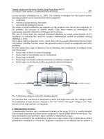
2.2 MR damper
The schematic configuration of the cylindrical type MR damper proposed in this work is
shown in Fig. 2. The MR damper is composed of the piston, cylinder and gas chamber. The
floating piston between the cylinder and the gas chamber is also used in order to
compensate for the volume induced by the motion of the piston. Also the gas chamber
Control Strategies for Vehicle Suspension System Featuring Magnetorheological (MR) Damper
99
(a) no magnetic field applied
(b) magnetic field applied
Fig. 1. Phenomenological behavior of MR fluid
which is filled with nitrogen gas acts as an accumulator for absorbing sudden pressure
variation of lower chamber of the MR damper induced by the rapid motion of the piston. The
MR damper is divided into the upper and lower chambers by piston, and it is fully filled with
the MR fluid. By the motion of the piston, the MR fluid flows through the annular duct
between inner and outer piston from one chamber to the other. The magnetic poles in the
piston head is placed to control the yield stress of the MR fluid by supplying current to the
coil. In order effectively to generate the magnetic field in the magnetic pole, the outer cylinder
and both ends of inner piston are made of ferromagnetic substance, while the center of the
inner piston is a paramagnetic substance. In the absence of a magnetic field, the MR damper
produces a damping force caused only by fluid viscous resistance. However, if a certain level
of magnetic field is supplied to the MR damper, the MR damper produces an additional
damping force owing to the yield stress of the MR fluid. This damping force of the MR
damper can be continuously tuned by controlling the intensity of the magnetic field.
In order to simplify the analysis of the MR damper, it is assumed that the MR fluid is
incompressible and that pressure in one chamber is uniformly distributed. The pressure drops
due to the geometric shape of the annular duct and the fluid inertia are assumed to be negligible.
For laminar flow in the annular duct, the fluid resistance is given by (Liu et al., 2006; White, 1994)
=8η
⁄
(1)
Particle
Base Oil
Magnetic Pole
N
S
Vibration Analysis and Control – New Trends and Developments
100
(a) MR damper
(b) piston (3-D view)
Fig. 2. Schematic configuration of the proposed MR damper
where η is the viscosity of the MR fluid and is the length of the annular duct.
and
are the inner radius of the outer piston and outer radius of the inner piston respectively.
By assuming that the gas does not exchange much heat with its surroundings, and hence
considering its relation as adiabatic variation, the compliance of the gas chamber is
obtained by
=
(2)
where
and
are the initial volume and pressure of the gas chamber respectively, and
is the specific heat ratio. On the other hand, the pressure drop due to the increment of the
yield stress of the MR fluid is given by
=2
()
(3)
where is a coefficient that depends on flow velocity profile and has a value range from 2.0
to 3.0,
is the length of the magnetic pole, ℎ is the gap of the annular duct, and
() is the
Control Strategies for Vehicle Suspension System Featuring Magnetorheological (MR) Damper
101
yield stress caused by the magnetic flux density . Therefore, the damping force of the
proposed MR damper can be written as
=
+
+
(4)
where
Parameter Value
Duct Length (L) 82mm
Piston Area (A
p
) 1661.90mm
2
Piston Rod Area (A
r
) 380.13mm
2
Duct Width (b) 123.53mm
Maximum Stroke 164mm
Table 1. Design parameters of the MR damper
=
,
=
−
=
−
(5)
where
and
are the piston displacement and velocity respectively,
and
represent
the piston and piston rod areas respectively, and
(
∙
)
is a signum function.
Fig. 3. Photograph of the manufactured MR damper
The photograph of the manufactured MR damper with optimally obtained design
parameters are shown in Fig. 3. The principal design parameters of the manufactured MR
damper, which can be applied to a mid-sized commercial passenger vehicle, are presented
Vibration Analysis and Control – New Trends and Developments
102
in Table 1. Fig. 4 presents the measured and analysed damping force F
D
characteristics of the
MR damper with respect to the piston velocity at various magnetic fields. This is obtained
by calculating the maximum damping force at each velocity. The piston velocity is changed
by increasing the excitation frequency from 0.5 to 4.0Hz, while the excitation amplitude is
kept constant ±20mm. This type of plot is frequently used in the damper manufacturing
industry to evaluate the level of damping performance. It is clearly observed that the
damping force is increased as the magnetic field increases, as expected. The damping force
response of the MR damper is measured as shown in Fig. 5. It can be found that the time
constant is about 23ms, which is obtained by inspecting the required time when the
damping force reaches 63.2percent of its final steady state value.
-0.6 -0.4 -0.2 0.0 0.2 0.4 0.6
-2000
-1500
-1000
-500
0
500
1000
1500
2000
0.0A (measured)
1.0A (measured)
2.0A (measured)
0.0A (analyzed)
1.0A (analyzed)
2.0A (analyzed)
Damping Force (N)
Velocity (m/s)
Fig. 4. Field-dependent damping force of the MR damper
0.00 0.05 0.10 0.15 0.20 0.25
400
800
1200
1600
2000
0
1
2
3
Damping Force
Current
Damping Force (N)
Time (sec)
Applied Current (A)
Fig. 5. Damping force responses of the MR damper
Control Strategies for Vehicle Suspension System Featuring Magnetorheological (MR) Damper
103
2.3 Quarter vehicle MR suspension
In order to investigate the effectiveness of vibration control algorithm, a quarter vehicle MR
suspension system is constructed as shown in Fig. 6. It shows that the proposed quarter
vehicle suspension model with the MR damper has two degrees of freedom. The spring for
the suspension is assumed to be linear and the tire is also modelled as linear spring
component. From the mechanical model, dynamic equation of system considering time
constant can be expressed as follows:
Fig. 6. Mechanical model of a quarter vehicle MR suspension system
=−
−
+
+
−
=
+
−
(
+
)
−
+
+
(6)
=−
+
Parameter Value
Sprung Mass (
) 373.5kg
Unsprung Mass (
) 40kg
Stiffness Coefficient (
) 27358N/m
Tire Stiffness Coefficient (
) 211625N/m
Damping Coefficient (
) 570Ns/m
Table 2. System parameters of the quarter vehicle suspension system
where
is time constant of the MR damper,
is the total stiffness coefficient of the
suspension, including the effective stiffness
of the MR damper in equation (4),
is the
damping coefficient of the suspension and is assumed to be equal to
,
is the vertical
stiffness of the tire, and
,
and
are the vertical displacements of sprung mass,
unsprung mass and road excitation respectively. The state space equation of proposed
quarter vehicle suspension can be expressed using dynamic equation (Lee et al., 2011):
=++
,=
(7)
u
m
s
m
s
z
u
z
r
z
s
k
s
c
d
F
t
k
Vibration Analysis and Control – New Trends and Developments
104
where
=
=
01 0 00
−
−
−
1
00 0 10
−
(
+
)
−
1
00 0 0−
1
, (8)
=0000
1
,=
000
0
,
=
10000
The system parameters of the quarter vehicle MR suspension system are chosen on the
basis of the conventional suspension system for a mid-sized passenger vehicle, and listed
in Table 2.
3. Control strategies
In order to evaluate vibration control performance of the quarter vehicle MR suspension
system, various control strategies are formulated and experimentally implemented.
3.1 Skyhook controller
Skyhook controller is simple but very effective control algorithm. It is well known that the
logic of the skyhook controller is easy to implement in the real field. The principle of
skyhook control is to design the active or semiactive suspension control so that the sprung
mass is linked to the sky in order to reduce the vertical oscillations of the sprung mass. Fig. 7
shows the conceptual scheme of skyhook controller for vehicle suspension system. The
desired damping force is set by
=
(9)
Fig. 7. Scheme of the skyhook controller for vehicle suspension system
Control Strategies for Vehicle Suspension System Featuring Magnetorheological (MR) Damper
105
where
is the control gain, which physically indicates the damping coefficient. In this
work, the value is chosen as 2470 using trial-and-error method.
3.2 LQG controller
Optimal control of a linear system with respect to the quadratic objective function under
incomplete measurements corrupted by white Gaussian noise is generally referred to as the
linear quadratic Gaussian (LQG) problem. The optimal control is a linear function of the
state estimates obtained from the Kalman-Bucy filter. The LQR (linear quadratic regulation)
is a state feedback problem, whereas LQG is an output feedback problem, which is more
realistic (Bahram & Michael, 1993). Fig. 8 shows the block diagram of an LQG controller. In
this study, the control input is formulated as follows:
u=−
(10)
where
is the estimated state. Control gain
is set as
−1248.3 1150.3 −4121.8 15.5 0.4
in this work.
3.3 H
∞ controller
In reality, the sprung mass of the vehicle is varied by the loading conditions such as the
number of riding persons and payload. And it makes the pitch and roll mass moment of
inertia to be changed. Therefore, in order to successfully control the vibration, a robust control
algorithm is required by considering the parameter variations of the system. From the
structured suspension model, a desirable damping force required to effectively suppress the
vibration is determined by adopting H∞ controller. Fig. 9 shows the nominal plant, perturbed
plant, shaped plant and loop gain graph. As shown in Fig., loop gain and perturbed plant are
well matched and it means loop perturbation is successfully constructed.
For reducing the steady state error and suppressing the effectiveness of disturbance,
weighting function can be designed as follows (Choi et al., 1999; 2002):
W=180
(11)
For the design of controller, design index γ is set as 2.99. Fig. 10 shows the sensitivity and
complementary sensitivity of the closed loop system. Therefore, control gain can be
calculated as follows:
u=
,
=
()
()
(12)
where
(
)
=−1.452
−2.294
−1.826
−1.128
−2.109
+5.2010−
6.916,
(
)
=
+92.03
+8.343
+3.835
+3.476
+3.487
+7.512.
3.4 Sliding mode controller (SMC)
Fig. 11 shows the conceptual scheme of sliding mode control algorithm. After the initial
reaching phase, the system states slides along the sliding surface. The first step to formulate
the SMC is to design a stable sliding surface. The stable sliding surface for the control
system is defined as follows:
s=
+
+
+
+
(13)
Vibration Analysis and Control – New Trends and Developments
106
Fig. 8. Block diagram of LQG controller
0.1 1 10 100 1000
-200
-150
-100
-50
0
50
Singular Value (dB)
Frequency (rad/s)
Norminal Plant
Perturbed Plant
Shaped Plant
Loop Gain
Fig. 9. Singular value plots of the quarter vehicle MR suspension system
0.1 1 10 100 1000
-100
-50
0
50
Singular Value (dB)
Frequency (rad/s)
Sensitivity
Complementary Sensitivity
Fig. 10. Frequency domain indicators of the quarter vehicle MR suspension system
-K
LQG
B
C
z
r
System
Linearized
Model
C
L
u(t)
x
y
(t)
+
-
Control Strategies for Vehicle Suspension System Featuring Magnetorheological (MR) Damper
107
Sliding surface
2
x
1
x
)(
0
tx
)(
1
tx
0
=
s
Reaching
Phase
Sliding Phase
Fig. 11. Scheme of the sliding mode control
where
(=1,2,3,4) are sliding surface coefficients to be determined so that the sliding
surface is stable. Then the sliding mode controller can be formulated which satisfies sliding
mode condition s<0 as follows (Choi et al., 2000):
u=−
+
(
−
−
+
+
−
)
+
+
(
+
−
(
+
)
−
+
)
+
−
(
)
,(>0)
(14)
where k stands for the discontinuous gain which is a positive number. The discrete gain can
be changed to continuous gain for reducing the chattering problem.
sat(s)=
/
|
/
|
≤1
(
)
|
/
|
>1
(15)
3.5 Moving sliding mode controller (MSMC)
It is required to reduce reaching phase to improve the performance and robustness of the
SMC. Reaching time can be successfully reduced in case that sliding surface is rotated or
shifted by considering reaching phase. Fig. 12 illustrates two moving patterns of the sliding
surface: rotating and shifting. The sliding surface for moving sliding mode controller can be
determined as follows:
s=
(
,
)
+
+
+
+
+
(
,
)
(
,
)
=
(
)
,
(
,
)
=
+
−Δ
(16)
where Δ
and Δ
are gain for surface rotating and surface shifting respectively.
is initial
value of
. The moving sliding mode controller can be formulated as follows:
u=−
(
,
)
+
(
−
−
+
+
−
)
+
+
(
+
−
(
+
)
−
+
)
+
+
(
,
)
−
(
)
,(>0)
(17)
Vibration Analysis and Control – New Trends and Developments
108
3.6 Fuzzy moving sliding mode controller (FMSMC)
The fuzzy moving sliding mode controller, which can change the coefficients and intercepts of
sliding surface by fuzzy tuning which takes into account for location of reaching phase, is
developed. Fig. 13 presents the block diagram of the proposed FMSMC. The basic
configuration of fuzzy control consists of three components: a fuzzification interface, a
decision-making logic and a deffuzification interface. In this study, the coefficient of sprung
mass displacement
is considered with priority while other coefficients of sliding surface are
fixed. Rotating algorithm, which can change the sliding surface
as a function of
, is
applied to reduce the reaching phase. However, it is hard to expect that the robustness is
enhanced in case that initial condition of reaching phase is located in quadrant 1 or quadrant 3.
Hence, shifting algorithm, which can change the intercept as a function of
, is adopted and
determined according to the relative place of sliding surface, and this will sufficiently reduce
the reaching phase. Therefore, the sliding surface can be written as follows (Cho et al., 2007):
s=
(
)
+
+
+
+
(
)
(18)
min
c
max
c
min
c
max
c
1
x
2
x
O
)(
0
tx
(a) rotating sliding surface
(b) shifting sliding surface
Fig. 12. Scheme of the moving sliding mode control
Control Strategies for Vehicle Suspension System Featuring Magnetorheological (MR) Damper
109
Fig. 13. Block-diagram of the proposed FMSMC
where
and are determined by tuning of fuzzy logic which takes into account for
displacement and direction of sprung mass displacement of
. In this case, the sliding
surface should maintain stability, although
and are changed according to time. In order
to reduce reaching time in the rotating algorithm,
should be high in case of the opposite
case. In the letter case, the sprung displacement
can be converted toward 0 more quickly.
In the shifting control algorithm, absolute value of should be high in case that absolute
value of
is large and vice versa. Furthermore, sliding surface is moved upward for
positive
and sliding surface is moved downward for the opposite case. Consequently, we
can formulate the following control input of the proposed FMSMC, which is combined
rotating and shifting algorithm:
u=−
(
)
+
(
)
(
)
−
(
)
⁄
(
)
+
(
−
−
+
+
−
)
+
+
(
+
−
(
+
)
−
+
)
−
−
(
)
,(>0)
(19)
The control input determined from the FMSMC is to be applied to the MR damper
depending upon the motion of suspension travel. The detailed control algorithm was
described by Cho et al., 2007.
3.7 Semi-active condition
The control input u directly represents the damping force of
. On the other hand, the
damping of the suspension system needs to be controlled depending upon the motion of
suspension travel. Therefore, the following semi-active actuating condition is imposed:
u=
(
−
)
>0
0
(
−
)
≤0
(20)
This semi-active condition can assure the increment of damping characteristic of the
suspension system and hence increase the stability of the system.
4. Control performances
Vibration control performances of the quarter vehicle MR suspension system are evaluated
under two types of excitation (road) conditions. The first excitation, normally used to reveal
the transient response characteristic, is a bump described by
MSMC
c
1
Defuzzification
Decision
Making
Fuzzification
α
Defuzzification
Decision
Making
Fuzzification
(Rotating)
(
Shiftin
g)
μ
μ
MR Suspension
x
1
x
1
Fuzzy Control
Vibration Analysis and Control – New Trends and Developments
110
=
1−cos()
(21)
where =2,=1/ and =/.
(=0.07m) is the bump height, (=0.8) is the
width of the bump and is the vehicle velocity. In the bump excitation, the vehicle travels
the bump with a constant vehicle velocity of 3.08km/h(=0.856m/s). The second excitation is
a random road conditions.
Fig. 14 shows the experimental apparatus of the quarter vehicle MR suspension system to
evaluate and compare the effectiveness of vibration isolation of the proposed control
algorithms. The MR suspension (assembly of the MR damper and spring), sprung mass and
tire are installed on the hydraulic excitation system. The sprung mass displacement and
excitation displacement are measured by LVDT (linear variable differential transformer) and
the suspension travel is measured by a wire sensor. The hydraulic system applies the road
profile to the MR suspension system. The current amplifier applies the control current
determined from the control algorithm to the MR damper.
Fig. 14. Experimental apparatus of the quarter vehicle MR suspension system
Fig. 15 presents vertical displacement, vertical acceleration of sprung mass and suspension
travel versus time responses of the MR suspension system for the bump excitation. As
shown in the Fig., it can obviously be found that unwanted vibrations induced from the
bump excitation are well suppressed by adopting the control algorithms in the MR
suspension system. Fig. 16 shows the performance comparison of vertical acceleration RMS
of the quarter vehicle MR suspension system for the bump excitation. The RMS value is
calculated from:
=
⋯
(22)
As shown in Fig., skyhook control algorithm shows quite good vibration control
performance. Also, Fig. 17 shows the PSD (power spectrum density) of sprung mass
acceleration in frequency domain for the random excitation and Fig. 18 shows the
performance comparison of vertical acceleration RMS of the quarter vehicle MR suspension
system for the random excitation. As expected, the PSD of the vertical acceleration has been
Acc.
Current
In
p
ut Si
g
nal
Dis
p
.
Com
p
uter
AD/DA
Converter
& Amplifier
Accelerometer
MR Suspension
LVDT
Hydraulic Unit
LVDT
Dis
p
.
Wire
Sensor
Disp.
Control Strategies for Vehicle Suspension System Featuring Magnetorheological (MR) Damper
111
1234
-0.05
0.00
0.05
0.10
0.15
Uncontrolled Skyhook
LQG Hinf
Vertical Disp. of SM (m)
1234
-3
-2
-1
0
1
2
3
Vertical Acc. of SM (m/s
2
)
1234
-0.03
-0.02
-0.01
0.00
0.01
0.02
0.03
Suspension Travel (m)
Time (sec)
1234
-0.05
0.00
0.05
0.10
0.15
Uncontrolled SMC
MSMC FMSMC
Vertical Disp. of SM (m)
1234
-3
-2
-1
0
1
2
3
Vertical Acc. of SM (m/s
2
)
1234
-0.03
-0.02
-0.01
0.00
0.01
0.02
0.03
Suspension Travel (m)
Time (sec)
Fig. 15. Bump responses of the quarter vehicle MR suspension system
UC SkyH LQG Hinf SMC MSMC FMSMC
0.0
0.1
0.2
0.3
0.4
RMS of Vertical Acc.
Fig. 16. Performance comparison of vertical acceleration RMS of the quarter vehicle MR
suspension system (bump)
Vibration Analysis and Control – New Trends and Developments
112
110
0
2
4
6
8
10
12
14
16
0.5
PSD of SM Acc. ((m/s)
2
/Hz)
Frequency (Hz)
Uncontrolled
Skyhook
LQG
Hinf
50
110
0
2
4
6
8
10
12
14
16
0.5
PSD of SM Acc. ((m/s)
2
/Hz)
Frequency (Hz)
Uncontrolled
SMC
MSMC
FMSMC
50
Fig. 17. Random responses of the quarter vehicle MR suspension system (72km/h)
UC SkyH LQG Hinf SMC MSMC FMSMC
0.0
0.5
1.0
1.5
RMS of Vertical Acc.
Fig. 18. Performance comparison of vertical acceleration RMS of the quarter vehicle MR
suspension system (random, 72km/h)
Control Strategies for Vehicle Suspension System Featuring Magnetorheological (MR) Damper
113
considerably reduced in the neighbourhood of body resonance (1~2Hz) by applying control
input. The control results presented in Figs. 15~18 indicate that ride comfort of a vehicle
system can be substantially improved by employing the MR suspension system associated
with the proposed control algorithms.
5. Conclusion
In this chapter, control algorithms for vibration control of the quarter vehicle MR
suspension system were proposed and its effectiveness was experimentally verified and
compared. In order to achieve this goal, a cylindrical MR damper was designed and
manufactured. After evaluating the field-dependent damping characteristics of the MR
damper, a quarter vehicle suspension system was then constructed and its governing
equations of motion were derived. In order to obtain a favourable control performance of
the MR suspension system, skyhook controller, LQG controller, H
∞ controller, sliding mode
controller, moving sliding mode controller and fuzzy moving sliding mode controller were
designed and experimentally realized to the quarter vehicle MR suspension system. It has
been experimentally shown that the proposed control algorithms can reduce the unwanted
vibration under bump excitation. In addition, it has been demonstrated that using the
proposed control methodologies vibration levels such as sprung mass acceleration under
random excitation can be significantly reduced at body resonance region. The results
presented here are self-explanatory justifying that the control strategies implemented in this
work can produce very similar vibration control performance. This directly indicates that
ride comfort of the vehicle system can be substantially improved by adopting the MR
suspension system associated with the proposed control strategies.
6. References
Bahram, S. and Michael, H. (1993). Control System Design Using MATLAB, Prentice Hall,
ISBN 0-13-174061-X, New Jersey
Carlson, J. D., Cantanzarite, D. M. and St.Clair, K. A. (1996). Commercial
Magnetorheological Fluid Devices. Electro-Rheological Fluids, Magneto-Rheological
Suspensions and Associated Technology, Vol.1996, pp. 20-28, ISBN 981-02-2676-4
Cho, J. W., Pang, Y. S., Choi, S. B. and Kim, K. S. (2007). Fuzzy Moving Sliding Mode
Control of Vehicle Suspension Featuring ER Shock Absorber. International
Conference on Electro-Rheological Fluids and Magneto-Rheological Suspensions, ISBN
978-981-2771-19-3, Lake Tahoe, USA
Choi, S. B., Han, S. S., Kim, H. K. and Cheong, C. C. (1999). H∞ Control of a Flexible Gantry
Robot Arm Using Smart Actuators. Mechatronics: Mechanics, Electronics, Control,
Vol.9, No.3, pp. 271-286, ISSN 0957-4158
Choi, S. B., Choi, Y. T. and Park, D. W. (2000). A Sliding Mode Control of a Full-Car
Electrorheological Suspension System Via Hardware in-the-Loop Simulation.
Journal of Dynamic Systems, Measurement, and Control, Vol.122, No.1, pp. 114-121,
ISSN 0022-0434
Choi, S. B., Lee, S. K. and Park, Y. P. (2001). A Hysteresis Model for the Field-Dependent
Damping Force of a Magnetorheological Damper. Journal of Sound and Vibration,
Vol.245, No.2, pp. 375-383, ISSN 0022-460x