Electromagnetic Waves Propagation in Complex Matter Part 3 docx
Bạn đang xem bản rút gọn của tài liệu. Xem và tải ngay bản đầy đủ của tài liệu tại đây (1.37 MB, 20 trang )
Fundamental Problems of the Electrodynamics of Heterogeneous
Media with Boundary Conditions Corresponding to the Total-Current Continuity
27
12
nn
DD
(8)
12
0EE
(9)
12
0
nn
BB
(10)
12
HH in
(11)
The indices (subscripts)
n and τ denote the normal and tangential components of the vectors
to the surface
S, and the indices 1 and 2 denote the adjacent media with different
electrophysical properties. The index τ denotes any direction tangential to the discontinuity
surface. At the same time, a closing relation is absent for the induced surface charge σ,
which generates a need for the introduction of an impedance matrix (Wei Hu & Hong Guo,
2002; Danae, D. et al., 2002; Larruquert, J. I., 2001; Koludzija, B. M., 1999; Ehlers, R. A. &
Metaxas, A. C., 2003) that is determined experimentally or, in some cases, theoretically from
quantum representations (Barta, O.; Pistora, I.; Vesec, I. et al., 2001; Broe, I. & Keller, O.,
2002; Keller, 1995; Keller, O., 1995; Keller, O., 1997).
The induced surface charge σ not only characterizes the properties of a surface, but also
represents a function of the process, i.e., σ(
E(∂E/∂t, H(∂H/∂t))); therefore, the surface
impedances (Wei Hu & Hong Guo, 2002; Danae, D. et al., 2002; Larruquert, J. I., 2001;
Koludzija, B. M., 1999; Ehlers, R. A. & Metaxas, A. C., 2003) are true for the conditions under
which they are determined. These impedances cannot be used in experiments conducted
under other experimental conditions.
The problem of determination of surface charge and surface current on metal-electrolyte
boundaries becomes even more complicated in investigating and modeling nonstationary
electrochemical processes, e.g., pulse electrolysis, when lumped parameters L, C, and R
cannot be used in principle.
We will show that σ can be calculated using the Maxwell phenomenological macroscopic
electromagnetic equations and the electric-charge conservation law accounting for the
special features of the interface between the adjacent media.
Separate consideration will be given to ion conductors. In constructing a
physicomathematical model, we take into account that
E
and
H
are not independent
functions; therefore, the wave equation for
E
or
H
is more preferable than the system of
equations (see Equations 6 and 7).
2. Electron conductors. New closing relations on the boundaries of adjacent
media
2.1 Generalized wave equation for
E
and conditions on the boundaries in the
presence of strong discontinuities of the electromagnetic field
2.1.1 Physicomathematical model
We will formulate a physicomathematical model of propagation of an electromagnetic field
in a heterogeneous medium. Let us multiply the left and right sides of the equation for the
total current (see Equation 6) by μμ
0
and differentiate it with respect to time. Acting by the
operator rot on the left and right sides of the first equation of Eq. (see Equation 7) on
condition that μ=const we obtain
Electromagnetic Waves Propagation in Complex Matter
28
2
00
11
total
g
rad div
t
j
EE
(12)
In Cartesian coordinates, Eq. (see Equation 12) will take the form
222
222
00
11
y
totalx x x x x z
E
EEE E E
txxyz
xyz
j
(13)
222
222
00
11
totaly y y y y
xz
EEE E
EE
tyxyz
xyz
j
(14)
222
222
00
11
y
totalz z z z x z
E
EEE E E
tzxyz
xyz
j
(15)
At the interface, the following relation (Eremin,Y. & Wriedt,T., 2002) is also true:
12
qx qx
div I I
t
i
(16)
Let us write conditions (see Equations 8–11) in the Cartesian coordinate system:
12
xx
DD
(17)
12
0
yy
EE
(18)
12
0
zz
EE
(19)
12
0
xx
BB
(20)
12
yy
z
HHi
(21)
12
zz
y
HHi
(22)
where i
τ
= i
y
j + i
z
k is the surface-current density, and the coordinate x is directed along the
normal to the interface. The densities i
y
and i
z
of the surface currents represent the electric
charge carried in unit time by a segment of unit length positioned on the surface drawing
the current perpendicularly to its direction.
The order of the system of differential equations (see Equations 13–15) is equal to 18.
Therefore, at the interface
S, it is necessary to set, by and large, nine boundary conditions.
Moreover, the three additional conditions (see Equation 17, 21, and 22) containing (prior to
the solution) unknown quantities should be fulfilled at this interface. Consequently, the total
number of conjugation conditions at the boundary
S should be equal to 12 for a correct
solution of the problem.
Differentiating expression (see Equation 17) with respect to time and using relation (see
Equation 16), we obtain the following condition for the normal components of the total
current at the medium-medium interface:
Fundamental Problems of the Electrodynamics of Heterogeneous
Media with Boundary Conditions Corresponding to the Total-Current Continuity
29
12
totalx totalx
div
ij j (23)
that allows one to disregard the surface charge σ. Let us introduce the arbitrary function f:
12
00xx
x
ff f
. In this case, expression (see Equation 23) will take the form
1
0
totalx
x
div
ij (24)
It is assumed that, at the medium-medium interface, E
x
is a continuous function of y and z.
Then, differentiating Eq. (see Equation 23) with respect to y and z, we obtain
1
totalx
x
div
yy
i
j (25)
1
totalx
x
div
zz
i
j
(26)
Let us differentiate conditions (see Equations 20–22) for the magnetic induction and the
magnetic-field strength with respect to time. On condition that
B=μμ
0
H
00
11
0, ,
yy
xzz
x
x
x
Bi
BiB
ttttt
(27)
Using Eq. (see Equation 7) and expressing (see Equation 27) in terms of projections of the
electric-field rotor, we obtain
0
x
x
rot
E and 0
y
z
x
E
E
yz
(28)
0
1
z
y
x
i
rot
t
E
or
0
1
xz z
x
EE i
zx t
(29)
0
1
z
z
x
i
rot
t
E
or
0
1
y
xz
x
E
Ei
xy t
(30)
Here, Eq. (see Equation 28) is the normal projection of the electric-field rotor, Eq. (see
Equation 29) is the tangential projection of the rotor on y, and Eq. (see Equation 30) is the
rotor projection on z.
Assuming that
E
y
and E
z
are continuous differentiable functions of the coordinates y and z,
from conditions (see Equations 18 and 19) we find
Electromagnetic Waves Propagation in Complex Matter
30
`
0, 0
0, 0
yy
xx
zz
x
x
EE
yz
EE
yz
(31)
In accordance with the condition that the tangential projections of the electric field on z and
y are equal and in accordance with conditions (see Equations 18 and 19), the expressions for
the densities of the surface currents i
z
and i
y
take the form
,
zz yy
x
x
iE iE
(32)
where
12
1
2
x
(33)
is the average value of the electrical conductivity at the interface between the adjacent media
in accordance with the Dirichlet theorem for a piecewise-smooth, piecewise-differentiable
function.
Consequently, formulas (see Equations 31–33) yield
0
x
divi
(34a)
Relation (see Equation 34) and hence the equality of the normal components of the total
current were obtained (in a different manner) by G.A. Grinberg and V.A. Fok (Grinberg,
G.A. & Fok, V.A., 1948). In this work, it has been shown that condition (34a) leads to the
equality of the derivatives of the electric field strength along the normal to the surface
0
x
x
E
x
(34b)
With allowance for the foregoing we have twelve conditions at the interface between the
adjacent media that are necessary for solving the complete system of equations (see
Equations 13–15):
a.
the functions E
y
and E
z
are determined from Eqs. (see Equations 18 and 19);
b.
E
x
is determined from condition (see Equation 24);
c.
the values of ∂E
x
⁄∂y, ∂E
x
⁄∂z, and ∂E
x
⁄∂x are determined from relations (see Equations 25
and 26) with the use of the condition of continuity of the total-current normal
component at the interface (see Equation 24) and the continuity of the derivative of the
total current with respect to the coordinate x;
d.
the values of ∂E
y
⁄∂y, ∂E
y
⁄∂z, and ∂E
z
⁄∂z are determined from conditions (see Equations 31
and 32) in consequence of the continuity of the tangential components of the electric
field along y and z;
e.
the derivatives ∂E
y
⁄∂x and ∂E
z
⁄∂x are determined from conditions (see Equations 29 and
30) as a consequence of the equality of the tangential components of the electric-field
rotor along y and z.
Fundamental Problems of the Electrodynamics of Heterogeneous
Media with Boundary Conditions Corresponding to the Total-Current Continuity
31
Note that condition (see Equation 23) was used by us in (Grinchik, N. N. & Dostanko, A. P.,
2005) in the numerical simulation of the pulsed electrochemical processes in the one-
dimensional case. Condition (see Equation 28) for the normal component of the electric-field
rotor represents a linear combination of conditions (see Equations 31 and 32); therefore, rot
x
E =
0 and there is no need to use it in the subsequent discussion. The specificity of the expression
for the general law of electric-charge conservation at the interface is that the components ∂E
y
⁄∂y
and ∂E
z
⁄∂z are determined from conditions (see Equations 31 and 32) that follow from the
equality and continuity of the tangential components E
y
and E
z
at the boundary S.
Thus, at the interface between the adjacent media the following conditions are fulfilled: the
equality of the total-current normal components; the equality of the tangential projections of
the electric-field rotor; the electric-charge conservation law; the equality of the electric-field
tangential components and their derivatives in the tangential direction; the equality of the
derivatives of the total-current normal components in the direction tangential to the
interface between the adjacent media, determined with account for the surface currents and
without explicit introduction of a surface charge. They are true at each cross section of the
sample being investigated.
2.1.2 Features of calculation of the propagation of electromagnetic waves in layered
media
The electromagnetic effects arising at the interface between different media under the action
of plane electromagnetic waves have a profound impact on the equipment because all real
devices are bounded by the surfaces and are inhomogeneous in space. At the same time, the
study of the propagation of waves in layered conducting media and, according to (Born,
1970), in thin films is reduced to the calculation of the reflection and transmission
coefficients; the function E(x) is not determined in the thickness of a film, i.e., the
geometrical-optics approximation is used.
The physicomathematical model proposed allows one to investigate the propagation of an
electromagnetic wave in a layered medium without recourse to the assumptions used in
(Wei Hu & Hong Guo, 2002; Danae, D. et al., 2002; Larruquert, J. I., 2001; Ehlers, R. A. &
Metaxas, A. C., 2003).
Since conditions (see Equations 23-32) are true at each cross section of a layered medium, we
will use schemes of through counting without an explicit definition of the interface between
the media. In this case, it is proposed to calculate E
x
at the interface in the following way.
In accordance with Eq. (see Equation 17), E
x1
≠E
x2
, i.e., E
x
(x) experiences a discontinuity of the
first kind. Let us determine the strength of the electric field at the discontinuity point x = ξ
on condition that E
x
(x) is a piecewise-smooth, piecewise-differentiable function having finite
one-sided derivatives ( )
x
Ex
and ( )
x
Ex
. At the discontinuity points x
i
,
0
0
( ) lim
i
ii i
i
x
x
i
Ex x Ex
Ex
x
(35)
0
0
( ) lim
i
ii i
i
x
x
i
Ex x Ex
Ex
x
(36)
In this case, in accordance with the Dirichlet theorem (Kudryavtsev, 1970), the Fourier series
of the function E(x) at each point x, including the discontinuity point ξ, converges and its
sum is equal to
Electromagnetic Waves Propagation in Complex Matter
32
1
00
2
x
EE E
(37)
The Dirichlet condition (see Equation 37) also has a physical meaning. In the case of contact of
two solid conductors, e.g., dielectrics or electrolytes in different combinations (metal-
electrolyte, dielectric-electrolyte, metal-vacuum, and so on), at the interface between the
adjacent media there always arises an electric double layer (EDL) with an unknown (as a rule)
structure that, however, substantially influences the electrokinetic effects, the rate of the
electrochemical processes, and so on. It is significant that, in reality, the electrophysical
characteristics λ, ε, and E(x) change uninterruptedly in the electric double layer; therefore, (see
Equation 37) is true for the case where the thickness of the electric double layer, i.e., the
thickness of the interphase boundary, is much smaller than the characteristic size of a
homogeneous medium. In a composite, e.g., in a metal with embedments of dielectric balls,
where the concentration of both components is fairly large and their characteristic sizes are
small, the interphase boundaries can overlap and condition (see Equation 37) can break down.
If the thickness of the electric double layer is much smaller than the characteristic size L of an
object, (see Equation 37) also follows from the condition that E(x) changes linearly in the EDL
region. In reality, the thickness of the electric double layer depends on the kind of contacting
materials and can comprise several tens of angstroms (Frumkin, 1987). In accordance with the
modern views, the outer coat of the electric double layer consists of two parts, the first of
which is formed by the ions immediately attracted to the surface of the metal (a "dense" or a
"Helmholtz" layer of thickness h), and the second is formed by the ions separated by distances
larger than the ion radius from the surface of the layer, and the number of these ions decreases
as the distance between them and the interface (the "diffusion layer") increases. The
distribution of the potential in the dense and diffusion parts of the electric double layer is
exponential in actual practice (Frumkin, 1987), i.e., the condition that E(x) changes linearly
breaks down; in this case, the sum of the charges of the dense and diffusion parts of the outer
coat of the electric double layer is equal to the charge of its inner coat (the metal surface).
However, if the thickness of the electric double layer h is much smaller than the characteristic
size of an object, the expansion of E(x) into a power series is valid and one can restrict oneself
to the consideration of a linear approximation. In accordance with the more general Dirichlet
theorem (1829), a knowledge of this function in the EDL region is not necessary to substantiate
Eq. (see Equation 37). Nonetheless, the above-indicated physical features of the electric double
layer lend support to the validity of condition (see Equation 37).
The condition at interfaces, analogous to Eq. (see Equation 37), has been obtain earlier
(Tikhonov, A. N. & Samarskii, A. A., 1977) for the potential field (where rot
E = 0) on the
basis of introduction of the surface potential, the use of the Green formula, and the
consideration of the discontinuity of the potential of the double layer. In (Tikhonov, A. N. &
Samarskii, A. A., 1977), it is also noted that the consideration of the thickness of the double
layer and the change in its potential at h/L
≪1 makes no sense in general; therefore, it is
advantageous to consider, instead of the volume potential, the surface potential of any
density. Condition (see Equation 37) can be obtained, as was shown in (Kudryavtsev, 1970),
from the more general Dirichlet theorem for a nonpotential vorticity field (Tikhonov, A. N.
& Samarskii, A. A., 1977).
Thus, the foregoing and the validity of conditions (see Equations 17-19 and 25 32) at each
cross section of a layered medium show that, for numerical solution of the problem being
considered it is advantageous to use schemes of through counting and make the
Fundamental Problems of the Electrodynamics of Heterogeneous
Media with Boundary Conditions Corresponding to the Total-Current Continuity
33
discretization of the medium in such a way that the boundaries of the layers have common
points.
The medium was divided into finite elements so that the nodes of a finite-element grid,
lying on the separation surface between the media with different electrophysical properties,
were shared by these media at a time. In this case, the total currents or the current flows at
the interface should be equal if the Dirichlet condition (see Equation 37) is fulfilled.
2.1.3 Results of numerical simulation of the propagation of electromagnetic waves in
layered media
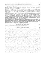
Let us analyze the propagation of an electromagnetic wave through a layered medium that
consists of several layers with different electrophysical properties in the case where an
electromagnetic-radiation source is positioned on the upper plane of the medium. It is
assumed that the normal component of the electric-field vector E
x
= 0 and its tangential
component E
y
= a sin (ωt), where a is the electromagnetic-wave amplitude (Fig. 2).
In this example, for the purpose of correct specification of the conditions at the lower
boundary of the medium, an additional layer is introduced downstream of layer 6; this layer
has a larger conductivity and, therefore, the electromagnetic wave is damped out rapidly in
it. In this case, the condition E
y
= E
z
= 0 can be set at the lower boundary of the medium. The
above manipulations were made to limit the size of the medium being considered because,
in the general case, the electromagnetic wave is attenuated completely at an infinite distance
from the electromagnetic-radiation source.
Numerical calculations of the propagation of an electromagnetic wave in the layered
medium with electrophysical parameters ε
1
= ε
2
= 1, λ
1
= 100, λ
2
= 1000, and μ
1
= μ
2
= 1 were
carried out. Two values of the cyclic frequency ω = 2π/T were used: in the first case, the
electromagnetic-wave frequency was assumed to be equal to ω = 10
14
Hz (infrared
radiation), and, in the second case, the cyclic frequency was taken to be ω = 10
9
Hz
(radiofrequency radiation).
Fig. 2. Scheme of a layered medium: layers 1, 3, and 5 are characterized by the
electrophysical parameters ε
1
, λ
1
, and μ
1
, and layers 2, 4, and 6 — by ε
2
, λ
2
, μ
2
.
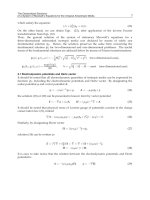
As a result of the numerical solution of the system of equations (see Equations 13–15) with
the use of conditions S (see Equations 24-34) at the interfaces, we obtained the time
Electromagnetic Waves Propagation in Complex Matter
34
dependences of the electric-field strength at different distances from the surface of the
layered medium (Fig. 3).
Fig. 3. Time change in the tangential component of the electric-field strength at a distance of
1 μm (1), 5 μm (2), and 10 μm (3) from the surface of the medium at λ
1
= 100, λ
2
= 1000, ε
1
=
ε
2
= 1, μ
1
= μ
2
= 1, and ω = 10
14
Hz. t, sec.
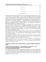
The results of our simulation (Fig. 4) have shown that a high-frequency electromagnetic
wave propagating in a layered medium is damped out rapidly, whereas a low-frequency
electromagnetic wave penetrates into such a medium to a greater depth. The model
developed was also used for calculating the propagation of a modulated signal of frequency
20 kHz in a layered medium. As a result of our simulation (Fig. 5), we obtained changes in
the electric-field strength at different depths of the layered medium, which points to the fact
that the model proposed can be used to advantage for calculating the propagation of
polyharmonic waves in layered media; such a calculation cannot be performed on the basis
of the Helmholtz equation.
Fig. 4. Distribution of the amplitude of the electric-field-strength at the cross section of the
layered medium: ω = 10
14
(1) and 10
9
Hz (2). y, μm.
Fundamental Problems of the Electrodynamics of Heterogeneous
Media with Boundary Conditions Corresponding to the Total-Current Continuity
35
Fig. 5. Time change in the electric-field strength at a distance of 1 (1), 5 (2), and 10 μm (3)
from the surface of the medium. t, sec.
The physicomathematical model developed can also be used to advantage for simulation of
the propagation of electromagnetic waves in media with complex geometric parameters and
large discontinuities of the electromagnetic field (Fig. 6).
(a) Distribution of the amplitude of the electric-
field strength in the two-dimensional medium
(b) Distribution of the amplitude of the
electric-field strength in depth
Fig. 6. Distribution of the amplitude of the electric-field strength in the two-dimensional
medium and in depth at ε
1
= 15, ε
2
= 20, λ
1
= 10
-6
, λ
2
= 10, μ
1
= μ
2
= 1, and ω= 10
9
Hz (the dark
background denotes medium 1, and the light background – medium 2). x, y, mm; E, V/m.
Electromagnetic Waves Propagation in Complex Matter
36
Figure 6a shows the cross-sectional view of a cellular structure representing a set
of parallelepipeds with different cross sections in the form of squares. The parameters
of the materials in the large parallelepiped are denoted by index 1, and the parameters of
the materials in the small parallelepipeds (the squares in the figure) are denoted by
index 2.
An electromagnetic wave propagates in the parallelepipeds (channels) in the transverse
direction. It is seen from Fig. 6b that, in the cellular structure there are "silence regions,"
where the amplitude of the electromagnetic-wave strength is close to zero, as well as inner
regions where the signal has a marked value downstream of the "silence" zone formed as a
result of the interference.
2.1.4 Results of numerical simulation of the scattering of electromagnetic waves in
angular structures
It is radiolocation and radio-communication problems that are among the main challenges
in the set of problems solved using radio-engineering devices.
Knowledge of the space-time characteristics of diffraction fields of electromagnetic waves
scattered by an object of location into the environment is necessary for solving successfully
any radiolocation problem. Irradiated object have a very intricate architecture and geometric
shape of the surface consisting of smooth portions and numerous wedge-shaped for
formations of different type-angular joints of smooth portions, surface fractures, sharp
edges, etc. – with rounded radii much smaller than the probing-signal wavelength.
Therefore, solution of radiolocation problems requires that the methods of calculation of the
diffraction fields of electromagnetic waves excited and scattered by different surface
portions of the objects, in particular, by wedge-shaped formations, be known, since the latter
are among the main sources of scattered waves.
For another topical problem, i.e., radio communication effected between objects, the most
difficult are the issues of designing of antennas arranged on an object, since their
operating efficiency is closely related to the geometric and radiophysical properties of its
surface.
The issues of diffraction of an electromagnetic wave in wedge-shaped regions are the focus
of numerous of the problems for a perfectly conducting and impedance wedge for
monochromatic waves is representation of the diffraction field in an angular region in the
form of a Sommerfeld integral (Kryachko, A.F. et al., 2009).
Substitution of Sommerfeld integrals into the system of boundary conditions gives a
system of recurrence functional equations for unknown analytical integrands. The
system’s coefficients are Fresnel coefficients defining the reflection of plane media or their
refraction into the opposite medium. From the system of functional equations, one
determines, in a recurrence manner, sequences of integrand poles and residues in these
poles.
The edge diffraction field in both media is determined using a pair of Fredholm-
type singular integral equations of the second kind which are obtained from the
above-indicated systems of functional equations with subsequent computation of
Sommerfeld integrals by the saddle-point approximation. The branching points of the
integrands condition the presence of creeping waves excited by the edge of the dielectric
wedge.
Fundamental Problems of the Electrodynamics of Heterogeneous
Media with Boundary Conditions Corresponding to the Total-Current Continuity
37
The proposed method is only true of monochromatic waves and of the approximate
Leontovich boundary conditions, when the field of the electromagnetic wave slowly varies
from point to point on a wavelength scale (Leontovich, 1948).
We note that the existing approximate Leontovich conditions have a number of other
constants and should be used with caution (Leontovich, 1948).
In actual fact, the proposed calculation method does not work in the presence of, e.g., two
wedges, when the sharp angles are pointed at each other, i.e., an optical knife, or in
diffraction of the electromagnetic wave on a system of parallel lobes, when the gap between
the lobes is in the region of microns, and the electromagnetic field is strongly “cut”
throughout the space with a step much than the wavelength.
A) Optical Knife
Figure 7 shows the field of an electromagnetic wave in its diffraction on the optical knife.
The parameters of the wave at entry and at exit are E
x
=10
4
sin(10
10
t), E
y
=10
4
cos (10
10
t).
The electrophysical characteristics are as follows: the wedge is manufactured from
aluminum: ε=1; μ=1; σ=3.774·10
7
S/m; the ambient medium is air.
The dimensions of the computational domain are 0.1×0.05 m. The calculation time 10
-9
sec,
and the time step is 10
-11
sec.
Numerical solution of the system of equations (13)-(15) yields the dependences of the
distribution Ex (x,y) и Ey (x,y) on the optical knife. The calculations results are in good
agreement with the existing experimental data and experiments specially conducted at the
Department of the Physics and Chemistry of Nonequilibrium Media of the A.V. Luikov
Heat and Mass Transfer Institute of the National Academy of Sciences by A.I. Bereznyak.
The experiments were carried out with an optical-range laser and were tentative in character
but the obtained experimental photographs of diffraction fields and the calculated results
turned out to be in good qualitative agreement. The authors express their thanks to A.I.
Bereznyak for the conducting of the experiments.
B) Diffraction Grating
The parameters of the wave and the interfacial conditions are the same, as those for the case
“optical knife”. The electrophysical characteristics are as follows: 2D lobes, ε=12; and σ=100
S/m; the ambient medium is air; the characteristics of the prism and the square are identical
to those of the lobes.
Figure 8 corresponds to a calculation time of 10
-10
sec; the time step is 10
-12
sec. Figure 9
corresponds to a calculation time of 10
-9
sec; the time step is 10
-11
sec.
It is seen from the modeling results that the proposed “comb” cab be used as a filter of a
high-frequency signal. Furthermore, we carried out numerical calculations of a modulated
signal at a frequency of 20 kHz. The results of the modulated-signal calculations are not
given. To analyze the difference scheme for stability was analyzed by the initial data. When
the time and space steps are large there appear oscillations of the grid solution and of its
“derivatives” (“ripple”) which strongly decrease the accuracy of the scheme. Undoubtedly,
this issue calls for separate consideration. The proposed algorithm of solution of Maxwell
equations allows circuitry-engineering modeling of high-frequency radio-engineering
devices and investigation of the propagation of electromagnetic waves in media of intricate
geometry in the presence of strong discontinuities of electromagnetic field.
The result of Para 2.1 were published in part (Grinchik, N.N et al., 2009).
Electromagnetic Waves Propagation in Complex Matter
38
(a) Mesh
(b) Amplitude E
x
(c) Amplitude E
x
(d) Isolines E
x
(e) Amplitude E
y
(f) Amplitude E
y
(g) Isolines E
y
Fig. 7. Mesh, amplitude E
x
and isolines, amplitude E
y
and isolines of the electromagnetic
field strength
Fundamental Problems of the Electrodynamics of Heterogeneous
Media with Boundary Conditions Corresponding to the Total-Current Continuity
39
(a) Amplitude E
x
(b) Isolines E
x
(c) Amplitude E
y
(d) Isolines E
y
Fig. 8. Amplitude E
x
and isolines, amplitude E
y
and isolines of the electromagnetic field
strength
(a) Amplitude E
x
(b) Isolines E
x
(c) Amplitude E
y
(d) Isolines E
y
Fig. 9. Amplitude E
x
and isolines, amplitude E
y
and isolines of the electromagnetic field
strength
Electromagnetic Waves Propagation in Complex Matter
40
2.1.5 Conclusions
We were the first to construct a consistent physicomathematical model of propagation of
electromagnetic waves in layered media without recourse to the matrices of the induced-
surface-charge impedances. This model is based on the Maxwell equations, the electric-
charge conservation law, the total-current continuity, and the Dirichlet theorem. Our
numerical investigations have shown that the physical and mathematical model proposed
can be used to advantage for simulation of the propagation of a high-frequency
electromagnetic wave in a medium consisting of layers having different electrophysical
properties.
2.2 Wave equation for
H
and conditions on the boundaries in the presence of strong
discontinuities of the electromagnetic field. numerical modeling of electrodynamic
processes in the surface layer
2.2.1 Introduction
During the interaction of an external magnetic field and magnetic abrasive particles, the
particles are magnetized, and magnetic dipoles with the moment oriented predominantly
along the field are formed. "Chains" along the force lines of the field (Shul’man, Z. P. &
Kordonskii ,V. I., 1982; Khomich, 2006) appear that periodically act on the processable
surface with a frequency ω=l/v. A fixed elemental area of the material periodically
experiences the effect of the magnetic field of one direction. Actually, the frequency and
duration of the pulse will be still higher because of the rotation of the magnetic abrasive
particle due to the presence of the moment of forces on contact and of the friction of the
particle against the processable part. In what follows, we will not take into account the effect
of rotation.
We assume that the particle velocity on the polisher is v. If the particle radius is r, then the
angular frequency is ω=2πv/r, and precisely this frequency determines the frequency of the
effect of the variable magnetic field component due to the fact that for a ferromagnetic μ>1.
The magnetic permeability μ of ferromagnetics, which are usually used in magnetic abrasive
polishing, is measured by thousands of units in weak fields. However, in polishing, the
constant external magnetic field is strong and amounts to 10
5
-10
6
A/m, and in this case the
value of μ for compounds of iron and nickel and for Heusler alloy decreases substantially.
Because of the presence of a strong external magnetic field H
0
the "small" absolute value of μ
of an abrasive particle leads to a periodic "increase" and "decrease" in the normal component
of the magnetic induction near the processable surface. In the present work we used
neodymium magnets (neodymium-iron-boron) with H
0
>485,000 A/m. The magnetic
permeability of a magnetic abrasive particle based on carbonyl iron was assumed in this
case to be equal to μ
1
=100.
Due to the continuity of the normal magnetic induction component B
n1
=B
n2
, where
B
n1
=μ
1
μ
0
H
1
; B
n2
=μ
2
μ
0
H
2
. For example, in glasses (μ
2
=1; therefore at the boundary of contact
of the glass with the magnetic abrasive particle an additional variable magnetic field of
strength H
1
> H
0
appears.
In (Levin, M. N. et al., 2003; Orlov, A. M. et al., 2001; Makara, V. A. et al., 2001; Rakomsin,
2000), magnetic field-induced effects in silicon are considered: a nonmonotonic change in
the crystal lattice parameters in the surface layer of silicon, the gettering of defects on the
surface, the change in the sorption properties of the silicon surface, and the change in the
mobility of the edge dislocations and in the microhardness of silicon.
Fundamental Problems of the Electrodynamics of Heterogeneous
Media with Boundary Conditions Corresponding to the Total-Current Continuity
41
In (Golovin, Yu. I. et al.; Makara ,V. A. et al., 2008; Orlov, A. M. et al., 2003), the influence of
an electromagnetic field on the domain boundaries, plasticity, strengthening, and on the
reduction of metals and alloys was established.
In view of the foregoing, it is of interest to find the relationship between the discrete-
impulse actions of a magnetic field of one direction on the surface layer of the processable
material that contains domains. According to (Shul’man, Z. P. & Kordonskii ,V. I., 1982), the
size of domains is as follows: 0.05 μm in iron, 1.5 μm in barium ferrite; 8 μm in the MnBi
compound, and 0.5-1 μm in the acicular gamma ferric oxide. According to (Akulov, 1961),
the size of a domain may reach 10
-6
cm
3
(obtained by the method of magnetic
metallography).
As a rule, an abrasive exhibits a distinct shape anisotropy, whereas the frequency of the
effect is determined by the concentration of abrasive particles in a hydrophobic solution and
by the velocity of its motion. We assume that on the surface of a processable crystal the
magnetic field strength H(t)=H
1
sin
4
(ωt) + H
0
.
It is required to find the value of the magnetic field strength in the surface layer that has the
characteristics λ
1
, ε
1
, and μ
1
and contains domains with electrophysical properties λ
2
, ε
2
, and
μ
2
. The domains may have the form of a triangular prism, a bar, a cylinder, etc.
2.2.2 Physicomathematical model. wave equation for H
We will formulate a physicomathematical model of propagation of electromagnetic waves in
a heterogeneous medium. The media in contact are considered homogeneous. We operate
with the operator rot on the left- and right-hand sides of the first equation for the total
current (see Equation 6) and multiply by μ
0
μ; then we differentiate the second equation in
Eq. (see Equation 7) with respect to time. Taking into consideration the solenoidality of the
magnetic field (see Equation 7) and the rule of repeated application of the operator
to the
vector
H, we obtain
2
2
00 0
2
1
t
t
HH
H
(38)
In the Cartesian coordinates Eq. (see Equation 38) will have the form
2222
00
2222
2222
00
2222
2222
00
2222
1
1
1
x x xxx
y y yyy
zz zzz
HH HHH
t
txyz
HH HHH
t
txyz
HH HHH
t
txyz
(39)
One fundamental electromagnetic field equation is the equation
0divB
. The use of the
Dirichlet theorem for approximation of the value of the magnetic field strength on the
boundaries between adjacent media analogously to that of the electric field strength does
not necessarily guarantees the observance of the condition of solenoidality of the magnetic
field; furthermore, the magnetic properties of heterogeneous media were assumed constant
Electromagnetic Waves Propagation in Complex Matter
42
in deriving generalized wave equations. The experience of numerical calculations has
shown that when it is necessary to model nonstationary magnetic phenomena it is better in
many cases to use a generalized wave equation for
E
, accordingly expressing
,Htr
by
,Etr
and, if need be, to perform backward recalculation to
,Htr
. This approach is
difficult to apply to modeling of heterogeneous media with different magnetic properties,
when the magnetic permeability µ is dependent on coordinates.
In media with a weak heterogeneity where μ (x, y, z) is a piecewise continuous quantity, the
application of the proposed method of through counting is quite justified. Indeed, the
system of equations (see Equations 13-15, 39) yields that the function’s discontinuity on the
boundaries between adjacent media is determined by the complexes which will be called the
generalized permeability
*
00
and the generalized conductivity
*
0
. Using the
Direchlet theorem for
*
and
*
, we obtain their values on the boundaries between adjacent
media and the values for the electric field strength at the discontinuity point (see Equation
37); here, we note that the value of the electric field strength is obtained without solving
Maxwell equations. In fact, at the discontinuity point, we use linear interpolation of the
function to obtain the values of
*
,
*
, and
1
00
2
x
EE E
. Consequently, for
piecewise continuous quantity μ (x, y, z), the application of the proposed method of through
counting is justified. We note that the equality of the derivatives of the electric field strength
along the normal to the surface at the discontinuity point according to Eq. (see Equation
34b) holds. When the wave equation for
H
is used for media with different magnetic
permeabilities the condition of equality of the derivatives fails, i.e.,
00
xx
xx
HH
xx
which is a consequence of Eq. (see Equation 10); therefore, the use of through-counting
schemes for the wave equation for
H
is difficult.
The generalized wave equation for
E
contains the term
g
rad divE
which directly allows for
the influence of induced surface charges on the propagation of waves. We note that the
proposed method of calculation can be used on condition that there are no built-in space
charges and extraneous electromotive forces (Grinberg, G.A. & Fok, V.A., 1948).
By virtue of what has been stated above, for modeling of the propagation of electromagnetic
waves in glasses having roughness and defects, we used system (see Equations 13-15) with
boundary conditions (see Equations 24-34)
2.2.3 Results of numerical simulation
The physicomathematical model developed can also efficiently be used in modeling the
propagation of electromagnetic waves in media with complex geometries and strong
electromagnetic field discontinuities.
The transverse cut of a cellular structure represents a set of parallelepipeds and triangular
prisms of various cross sections, as depicted in Fig. 10a and 11a. An electromagnetic wave
propagates across the direction of parallelepipeds and triangular prisms (channels) along
the coordinate
x.
Fundamental Problems of the Electrodynamics of Heterogeneous
Media with Boundary Conditions Corresponding to the Total-Current Continuity
43
(a) Amplitude H
x
(b) Isolines
Fig. 10. Amplitude
H
x
and isolines of the magnetic field strength
The size of the investigated two-dimensional object is 14×20·10
-6
m, and the sizes of the
domains are
2–4 μm. The frequency of the influence of the magnetic field is ω= 2π·10
6
, and
the strength of the field is
54 6
21 10 sin 2 10 /
x
HtAm
(40)
(a) Amplitude H
y
(b) Isolines
Fig. 11. Amplitude
H
y
and isolines of the magnetic field strength
The electrophysical properties are as follows: of the large parallelepiped, μ= 1, ε= 8, σ = 10
-9
Ω·m; of domains, μ= 1, ε= 6, σ = 10
-8
Ω·m. They correspond to the electrophysical properties
of glasses.
It was assumed that in a layer of thickness 15-20 μm an electromagnetic wave propagates
without attenuation; therefore, on all the faces of the large parallelepiped the fulfillment of
condition (see Equation 40) was considered valid. On the faces of the parallelepiped that are
parallel to the
OX axis condition (see Equation 40) corresponded to the "transverse"
tangential component of the wave; on the faces parallel to
OY condition (see Equation 40)
corresponded to the normal component of the field.
The calculations were carried out with a time step of 10
-13
sec up to a time instant of 10
-10
sec.
Figures 10a and 11a present the amplitude values of the magnetic field strength along
H
x
and H
y
with a comparison scale, whereas Figs. 11b and 11b present the corresponding
isolines. An analysis of these figures shows that at the places of discontinuity, on the
wedges, force lines of the electromagnetic field concentrate. According to (Akulov, N. S.,
Electromagnetic Waves Propagation in Complex Matter
44
1939), precisely wedges are often the sources and sinks of the vacancies that determine, for
example, the hardness and plasticity of a solid body.
Also, we modeled the propagation of waves in media, when domains possess magnetic
properties. We assumed, in the calculations, that μ=100; the remaining parameters
correspond to the previous example of solution (Fig. 12)
(a) Amplitude
H
x
(b) Amplitude H
y
Fig. 12. Amplitude
H
x
and H
y
of the magnetic field strength
Of interest is the interaction of the electromagnetic wave with the rough surface shown in
Fig. 13 and 14. As in the previous examples, we observe the concentration of
electromagnetic energy on angular structures.
(a) Amplitude
H
x
(b) Isolines
Fig. 13. Amplitude
H
x
and isolines of the magnetic field strength
(a) Amplitude
H
x
(b) Isolines
Fig. 14. Amplitude
H
y
and isolines of the magnetic field strength
Fundamental Problems of the Electrodynamics of Heterogeneous
Media with Boundary Conditions Corresponding to the Total-Current Continuity
45
From Fig. 13 and 14, it is seen that electromagnetic heating of tapered structures may occur
in addition to mechanical heating in magnetic abrasive machining.
As we have mentioned above, for investigation of the propagation of electromagnetic waves
in nonmagnetic materials, it is more expedient to use the generalized equation for
E
. For
the purpose of illustration we give an example of numerical calculation of an optical knife
with the wave equation for
H
(Fig. 15).
From Fig. 15, it is seen that the actual problem of diffraction on the optical knife remains to
be solved, i.e., there is no “glow” on the optical-knife section, which is inconsistent with
experimental data.
(a) Amplitude H
x
(b) Amplitude H
y
Fig. 15. Amplitude
H
x
and H
y
of the magnetic field strength
As is known (Bazarov, 1991), in thermodynamically equilibrium systems the temperature
T
and the electrical φ and chemical μ
c
potentials are constant along the entire system:
0, 0, 0
c
g
rad T
g
rad
g
rad
(41)
If these conditions are not fulfilled (grad
T≠0, grad φ≠0, grad μ
c
≠0), irreversible processes of
the transfer of mass, energy, electrical charge, etc. appear in the system.
The chemical potential of the
j-th component is determined, for example, as a change of the
free energy with a change in the number of moles:
,
/
cj j
TV
Fn
(42)
Where
dF SdT PdV HdB
(43)
The last term in Eq. (see Equation 43) takes into account the change in the free energy of a
dielectric due to the change in the magnetic induction. The free energy of a unit volume of
the dielectric in the magnetic field in this case has the form
2
00
,
2
H
FTD F
(44)
We assume that changes in the temperature and volume of the dielectric are small. Then the
mass flux is determined by a quantity proportional to the gradient of the chemical potential
or, according to Eq. (see Equation 43), we obtain
Electromagnetic Waves Propagation in Complex Matter
46
cc
i
q D grad HdB D grad W
(45)
where
2
0
2
H
W
is the density of the magnetic field in the unit volume of the dielectric.
In magnetic abrasive polishing on the sharp protrusions of domains the gradients of
magnetic energy are great, which can lead to the origination of vacancy flows.
An analysis of the results shows that the nonstationary component of the full
electromagnetic energy is also concentrated in the region of fractures and wedges, i.e., at the
sharp angles of domains, which may lead to the improvement of the structure of the
sublayer of the treated surface due to the "micromagnetoplastic" effect. Maximum values of
the nonstationary part of the total electromagnetic energy
W
max
in the sublayer correspond
to a maximum value of the function sin (2π·10
6
t) and occur for the time instants t = (n/4)10
-6
sec, where
n is the integer, with the value of W
max
for a neodymium magnet and a
magnetoabrasive particle on the basis of carboxyl iron amounting to a value of the order of
(see Equations 5-6)·10
6
J/m
3
. Having multiplied W
max
by the volume of a domain, vacancy,
or atom, we may approximately obtain the corresponding energy. The density of the
electromagnetic energy in all of the cases is much smaller than the bonding energy of atoms,
10
-18
-10
-19
J. However, a periodic change in the magnetic field in one direction leads to a
ponderomotive force that may influence the motion of various defects and dislocations to
create a stable and equilibrium structure of atoms and molecules in magnetic abrasive
polishing and, in the long run, in obtaining a surface with improved characteristics due to
the "micromagnetoplastic" effect. The result of Para 2.2 were published in part (Grinchik,
N.N. et al., 2010).
3. Interaction of nonstationary electric and thermal fields with allowance for
relaxation processes
We investigate electric and thermal fields created by macroscopic charges and currents in
continuous media. Of practical interest is modeling of local heat releases in media on
exposure to a high-frequency electromagnetic field. We should take into account the
influence of the energy absorption on the propagation of an electromagnetic wave, since the
transfer processes are interrelated.
In an oscillatory circuit with continuously distributed parameters, the energy dissipation is
linked (Kolesnikov, 2001) to the dielectric loss due to the dependence of the relative
permittivity ε(ω) on frequency. In the general case ε is also complex, and the relationship
between the electric displacement and electric field vectors has the form
D=ε(ω)E, where
ε(ω)= ε'(ω) –
iε''(ω); here, ε' and ε'' are determined experimentally. As of now, the problems
of dielectric heating of a continuous medium are reduced in many cases to consideration of
an equivalent circuit based on lumped parameters, such as capacitance, inductance, loss
angle, and relative-dielectric-loss factor (Skanavi, 1949; Perre P.; Turner I. W., 1996), that are
established experimentally.
With this approach, there arise substantial difficulties in determining the temperature field
of equivalent circuits. Also, we have polarization and the occurrence of an electric double
layer of a prescribed electric moment in contact of media with different properties.
Equivalent circuits in lamellar media additionally involve empirical lumped parameters:
surface capacitance and surface resistance (Jaeger, 1977). The total current can always be
separated into a dissipative, or conduction current which is in phase with the applied
voltage and a displacement current shifted in time relative to the voltage. The exact physical