New Perspectives in Biosensors Technology and Applications Part 14 pot
Bạn đang xem bản rút gọn của tài liệu. Xem và tải ngay bản đầy đủ của tài liệu tại đây (4.13 MB, 30 trang )
New Perspectives in Biosensors Technology and Applications
382
etc. Then, such signal must me amplified and then processed. This amplifier module is the
detector stage (c). Thinking in electrical signals, an amplifier stage is used to amplify the
biological signal, which is generally very low. Then, (d) is the electronics module which has
the role to process such measurements. Finally, (e), the results are presented thanks to a
user-friendly interface to visualize the data.
Fig. 6. Generic components of a biosensor.
2.3.2 Electrochemical biosensors
Electrochemical biosensors are the largest group of chemical sensors. All of them are based
on fixing some variables of the electrochemical cell and check how the other variables
change with the fluctuations of the controlled variables. These biosensors are normally
based on enzymatic catalysis of a reaction that produces or consumes electrons (such as
enzymes are rightly called redox enzymes). The sensor substrate usually contains three
electrodes, a reference, an active or working and a counter or auxiliary electrode.
Electrochemical sensors allow three main different configurations: voltammetric,
potentiometric and conductrometric measurements. Voltammetric biosensors are those
based on the measurement of the current-voltage variations. Voltammetric measurements
typically consist of a three-electrode arrangement. Measurement of current occurs at the
redox electrode as a function of the electrode potential. The solution must contain electro
active species that can undergo electrode reaction. Amperometric biosensors are a particular
case of them, where is determined electrical currents associated with a redox process where
a fixed voltage in the sensor is applied. In potentiometric biosensors, the electrode and
solution are in chemical equilibrium, the current flow is near zero and a voltage is measured
relative to a reference electrode. Conductometric biosensors are based on the measurement
of the variations of the conductance with the use on an alternating current at a fixed
frequency of operation. Special interests, as is stated in more detail in the next section, have
Impedance biosensors that determine variations of the impedance of the sensor.
For voltammetry biosensors, and in particular for amperometric biosensors, the most
standard measurement method is based on the three-electrode configuration. By applying a
proper fixed potential between them, a current is generated, which is related to the
concentration of the electro active species in the sample solution. These species are
generated by oxidation or reduction in the sample solution. The potentiostat amplifier,
presented in 2.4.2, controls the voltage between the working and reference electrodes, and
the current through the electrochemical cell formed by the three electrodes of the biosensor
and the solution where the reaction takes place is conveyed through the counter electrode.
Based on the use of the potentiostat amplifier, there are different kind of electrochemical test
Portable Bio-Devices:
Design of Electrochemical Instruments from Miniaturized to Implantable Devices
383
that can be carried out in order to analyze the electrochemical cell formed by the biosensor
and the solution media, Fig. 8. The most popular electrochemical technique used with
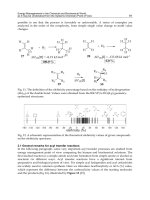
electrochemical sensor is the cyclic voltammetry, depicted in Fig. 7.
Fig. 7. Cyclic voltammetry.
Fig. 8. Randles model.
The voltage applied in b) is fixed by the potentiostat between the working and reference
electrodes. In a) is depicted the characteristic cyclic voltammetry, where the path between
point (a) and (b) represent the reduction phase, that is, the electrons are derived to the
solution from the electrodes. During the path (c) to (d) the oxidation takes place. The
chemical species pass electrons to the electrode. Characteristic peaks for the oxidation and
reduction are obtained, (d) and (a) respectively. Different voltage ramps define different
reactions. Also, for different concentrations of the analytes the peaks of reduction and
oxidation change, as depicted in c). Based on this technique the amperometric analysis is
introduced. As it was mentioned above, a fixed voltage now is fixed and the current is
directly measured. Usually this voltage is fixed at that point where the electrochemical
response is maximized. In d) is depicted this situation of the maximum point of oxidation,
and for different concentrations. Several other techniques are used for a voltammetric
New Perspectives in Biosensors Technology and Applications
384
analysis like staircase or sampled DC voltammetry, normal pulse voltammetry, differential
pulse voltammetry, square wave voltametry and differential normal pulse voltammetry. All
of these techniques are based in a potential that is scanned, defining an initial and final steps
of voltage vs. time.
Fig. 9. Plof the Bode Polt for an EIS.
Fig. 10. Plot of the Nyquist Polt for an EIS.
The Electrochemical Impedance Spectroscopy (EIS), is a more effective method to probe the
interfacial properties of the modified electrode through measuring the change of electron
transfer resistance at the electrode surface, which is caused by the adsorption and
desorption of chemical or biological molecules. There are different electrical models that
represent the electrochemical cell, and the easiest one is the Randles model, Fig. 8, just
Portable Bio-Devices:
Design of Electrochemical Instruments from Miniaturized to Implantable Devices
385
defined by three elements: by the double-layer capacitor in parallel with a polarization
resistor, which is also described as a charge transfer resistor, and the solution resistor. In an
electrochemical cell, electrode kinetics, redox reactions, diffusion phenomena and molecular
interactions at the electrode surface can be considered analogous to the above components
that impede the flow of electrons in an ac circuit. The measurement of the impedance
variation of the cell can be depicted following two different approaches: a) the magnitude
and phase of the impedance are depicted as a Bode plot, as depicted in Fig. 9, or b) a Nyquist
plot, Fig. 10, where in the complex plane are depicted the real impedance component in the X
coordinates, and the imaginary impedance component in the Y coordinates.
2.3.3 Some examples
Most of the biosensors are based on electrochemical transducer method. The clearest
example is the blood glucose monitoring marker, based on amperometric enzyme
biosensors. Here an enzyme glucose oxidise catalyses the conversion of the analyte to a
molecule that can be detected by the transducer. First, it oxidises glucose and uses two
electrons to reduce a component of the enzyme, FAD to FADH2, which is also oxidased. The
resulting current in the electrode is a measurement of the concentration of glucose.
Oxidades oxidize their substrates and they need oxygen as a co-substrate, re-oxidizing the
enzyme to the initial state. The hydrogen peroxide produced is again oxidized at the
electrode:
Glucose+ O
2
' Gluconolactone + H
2
O
2
The glucose oxidase with its prosthetic group FAD
Glucose + FAD ' Gluconolactone + FADH
2
FADH
2
+ O
2
' H
2
O
2
+ FAD
And at the electrode takes place an anodic reaction, on platinum, @ 0.6V vs. Ag/AgCl; 3M.
H
2
O
2
' 2H
+
+O
2
+ 2e
-
Then, the detected current by the potentiostat, which is proportional to the concentration of
the analyte in the sample, is:
I
d
= n·A·F·D
s
·c
0
/ δ
N
(1)
Where A is the area of the electrode, D
S
is the diffusion coefficient of the analyte S, c
0
is the
bulk solution concentration of the analyte and finally δ
N
is the thickness of the stagnant
layer.
The glucose biosensor (Fiorito and De Toresi, 2001; Hiller et al., 1996; Kros et al., 2001) is an
example of this this applications. The biosensor is based on the electron transfer that occurs
during the enzymatic reduction of glucose. Nowadays, there is an increasing interest in the
field of glucose biosensors, looking for Glucose Continous Monitoring (GCM). In the last
years several works have been published in the field like Patel et al., (2007), where it’s
presented an electro-enzymatic glucose sensor, (Xi Huang et al., 2009), where it is
introduced a capacitive based MEMS affinity sensor for continuous glucose monitoring
applications, (Teymoori, Mir Majid et al., 2009) introducing a MEMS for glucose and other
generical sensors in medical applications and (Rodrigues et al., 2007) where it’s developed a
New Perspectives in Biosensors Technology and Applications
386
new cell-based biochip dedicated to the real-time monitoring of transient effluxes of glucose
and oxygen, using arrays of amperometric microsensors integrated in the inlet and the
outlet of a PDMS cell chamber, and complete designs like (Rahman et al., 2009) where is
presented the design, microfabrication, packaging, surface functionalization and in vitro
testing of a complete electrochemical cell-on-a-chip (ECC) for the continuous amperometric
monitoring of glucose, performing cyclic voltammetry, electrical impedance spectroscopy
(EIS), and microscopic examination.
Special interest has the development of nanosensors applied in this field. Some examples are
reported, like (Usman Ali, S.M et al., 2009), where ZnO Nanowires are used for a GCM
application directly connected to the gate of a standard low-threshold MOSFET, (Lee Y.J. et
al., 2009), where a flexible enzyme-free glucose micro-sensor with nanoporous platinum
working electrode on a bio-compatible PET film was designed, (Goud et al., 2007), where it’s
presented nanobioelectronic system-on-package (SOP) with integrated glucose sensor based
on carbon nanotubes working electrodes, (Jining Xie et al., 2007) where it’s studied a
platinum nanoparticle-coated carbon nanotubes for amperometric glucose biosensing, or in
(Ekanayake, E.M.I et. al., 2007) where it’s described fabrication and characterization of a
novel nano-porous polypyrrole (PPy) electrode and its application in amperometric
biosensors, with enhanced characteristics for glucose sensing.
2.4 Electronics for electrochemical biosensors
2.4.1 Two and three electrodes configurations
Two are the minimum of electrodes that are required in order to control the interface
between an electrode and a solution, forming a simple electrochemical cell. One of these
electrodes is the working electrode (W), where the reaction of interest takes place. The other
electrode is the reference electrode (R) where is fixed a constant potential reference.
Generally for a voltammetry experience this approach it is not enough when the potential
applied must be controlled owing to the equivalent resistance of the solution. Then, when a
current circulates through the solution a voltage drop is generated. Also, when current is
present at the reference electrode implies a variation of the voltage interface of it. This
situation implies that the voltage difference between the reference and the working
electrodes is not well defined. A simple solution is based on the use of a large reference
electrode and a small working electrode but sometime this is not possible. The solution to
this situation is the use of a three-electrode system, placing an extra electrode which is
usually called counter (C) or auxiliary electrode, as is depicted in Fig. 11. The voltage
difference is fixed between the (W) and (R) electrodes and the current is injected by the (C)
electrode and the potential is well defined at the cell (Vcell). The potentiostat amplifier is the
instrumentation that has the role to control this bias and read the current of the cell.
2.4.2 The potentiostat amplifier
The main electronics involved in the design of the instrumentation are defined by the
potentiostat amplifier, to drive and control the electrodes, and to measure the output signal
and the processing electronics. The potentiostat amplifier is the electrochemical measurement
technique to interface the biological elements with the electronics. Electronic measurement
of the biochemical analyte concentrations is essential for diseases diagnose and study of
biological systems.
Two different ways can be followed: a) the potentiometric configuration, where a fixed
current it is applied and the output voltage is measured, or b) the amperometric
Portable Bio-Devices:
Design of Electrochemical Instruments from Miniaturized to Implantable Devices
387
Fig. 11. Two and Three-electrode electrochemical measurement system.
configuration, where a fixed voltage is applied and the output current is read, and
converted to a voltage signal by the transimpedance amplifier. If the size of the electrodes is
decreased, defining micron-sized electrodes, the current level decreases up to femto-
amperes. Some references are described in (Choi Myung-suk et al., 2007), in their work
“Implantable Bio system design for displacement measurement of living life”, in the work
by (K.Kitamori, 2007), where he described micro and nano chemical sensors on-a-chip, and
the by (Wen-Yaw Chung et al., 2007), where they present a low power readout circuit with
an potentiostat amplifier for amperometric chemical sensors for a Glucose Meter
Application. Other interesting biosensors are the piezoelectric immunosensors, like the
developed for the rapid diagnosis of M. tuberculosis by (Eric Carnes et al., 2005).
The state of the art of the potentiostat amplifiers has evolved in such a different ways from
discrete or integrated solutions. In order to design a portable system for standard
electrochemical assays, discrete solutions become an extremely good choice in terms of
portability, accuracy and economical cost. But, demands for increased functionality, reduced
system size, reduced electrodes size, ultra-low current detection and versatility will force
potentiostats to be designed on a system-on-chip (SoC) to be implemented in advanced
CMOS processes. The scaled supply voltages in these processes (Kakerow et al., 1995;
Kraver et al., 2001; Reay et al., 1994), however, seriously limit the chemical analysis range.
The drive voltages of amperometric chemical sensors do not scale with electrode size, but
are instead defined by the reduction/oxidation (redox) potentials of the analysis been
investigated. In fact, many analysis are undetectable using standard potentiostats in a
0.18µm CMOS process due to its maximum supply voltage of 1.8V (Kissinger et al., 1996).
Standard, single-ended (SE) potentiostats force the sensor’s electrode to a fixed potential,
Fig. 12, while fully differential (FD) potentiostat, employing a FD operational amplifier,
dynamically controls the electrode’s potential and doubles its voltage swing.
2.4.3 The lock-in amplifier
EIS is an ac method that describes the response of an electrochemical cell to a small
amplitude sinusoidal voltage signal as a function of frequency. EIS technique consists on
applying an AC voltage to the R- W electrodes and measure the resulting AC current at the
Working electrode (Fig. 13). Then, it is possible to represent the impedance of the
electrochemical cell. The resulting current sine wave differs in time (phase shift) with
respect to the perturbing (voltage) wave, and the ratio V(t)/I(t) is defined as the impedance
(Z), that accounts for the combined opposition of all the components within the
New Perspectives in Biosensors Technology and Applications
388
electrochemical cell (resistors, capacitors, inductors) to the flow of electrons. The variations
in the electronic signal are due to the antibody-antigen (Ab-Ag) interactions. The signal
processing circuitry has the role to obtain the real and imaginary components of the
measurement of the Electrochemical Impedance.
Fig. 12. Potentiostat Amplifier with electrochemical sensor’s model.
Fig. 13. Generic setup for an EIS experiment.
Based on the nature of the measured signal there are two main approaches: a) the capacitive
immunosensors, where the surface of the electrode is completely covered by a dielectric
layer and the whole electrode assembly behaves as an insulator. The variation of the
capacitance is measured, in frequency ranges up to 100kHz, and b) the faradaic
Portable Bio-Devices:
Design of Electrochemical Instruments from Miniaturized to Implantable Devices
389
immunosensors, which have the surface of the electrode partially or wholly covered by a
non insulating layer or partially covered by an insulating layer, are able to catalyse a redox
probe that exists in the measuring solution. In this case, the measured parameter is the
charge transfer resistance (the real component of impedance at low frequency values,
typically 0.1-1.0 Hz), and Ab-Ag interactions are expected to cause an increase in its value as
the faradic reaction becomes increasingly hindered.
In order to proceed with the signal processing, there are mainly two approaches: a) the Fast
Fourier Transform (FFT), and b) the Frequency Response Analyzer (FRA). In the case of the
FFT, a pulse or step, -the approach to be followed is the ideal Dirac delta function-, is
applied to the sample because it contains a wide frequency content. Then, the response of
the sample is digitized and processed in a digital processor, for instance a DSP, and using
the FFT algorithm, the different frequency components are obtained for their analysis. Also,
other possibility that could be followed is the logarithmic sampling in the DFFT calculus,
reducing the data that must be required in the process. A simpler solution is based on the
FRA approach. In this case, a sine and cosine signals are adopted, and using two multipliers
and a filter stage the real an imaginary components of the response are obtained. This
measurement must be done for each frequency. Working with just one sensor and in terms
of the size of the final product, the FFT option could be adopted, because the response for
several frequencies is obtained. The FRA solution is a solution more oriented to multi-sensor
approaches but also in the case of single sensors it is a nice option, in terms of the trade-off
between complexity and speed, if not too low frequencies must be measured. This lock-in
approach is more feasible.
2.5 Integration of lab on a chip devices
The fabrication of lab-on-a-chip devices require the integration of several systems such as
microfluidic, detection (BioLED Technology, 2007), power supply (Colomer et al., 2008)
and/or communication in a small and portable device.
The aim of the microfluidic system is to transport the fluid into the microcapillaries as well
as its preparation for their proper analysis. The preparation step consists in the separation of
the fluidic and/or suspended particles (Rodríguez-Villarreal et al., 2010), the mixing of the
fluids for cell activation and/or mixing reactants for initiation. It could takes place along the
capillaries or inside of created droplets (Xia et al. 2010), which can also be useful to
encapsulate biological particles or chemical reagents. In some cases, the sample needs to be
focalized (Rodríguez-Trujillo et al., 2008) before it flow through the electrical or optical
detection system (Fig. 14) to achieve a better detection signal.
A complete portable lab-on-a-chip device required an integrated power supply for the
functionality of the detection and the communications systems. The last one, has the
objective to inform by sending the relevant results of the biological analysis.
The integration of all these Microsystems requires sophisticated microfabrication techniques
such as photolithography, chemical vapour deposition, dry and wet etching and many more
(Chen, 2006; Chinn, 2008) to create a final prototype made of biocompatible materials. The
integration of the silicon, polymer or glass devices are the main concerns of research groups.
There are two ways of integrating such microdevices, the fabrication of all of them on the
same device or the assembly of several microdevices previously fabricated as shown in
Fig. 15. A). But up to now, although there are many portable devices, the lab on a chip
technology still required of external sources for energy supply and the human-device
interface.
New Perspectives in Biosensors Technology and Applications
390
Fig. 14. Microsystems required for a complete Lab-on-chip device.
Different companies of biomedical devices such as Philips, Biosite Inc. and Medimate are
developing small devices that integrate some fluidic/detection microsystems with portable
power/interface macrosystems to commercialize analytical biomedical devices, Fig 15.B.
Besides, the development of a full custom lab-on-a-chip device envisaged for implantable
applications, keeps been the objective of the new medical technologies.
Fig. 15. Scheme of integration of A) full lab-on-a-chip devices and B) portable and
microdevices.
3. An example of a miniaturized electrochemical instrument for in- situ O
2
monitoring
The decrease of oxygen concentration in water is a clear indication of water pollution, which
is one of the main concerns of the Water Framework directive in the European Union, as the
pollution is mainly due to nitrogen-based fertilisers used in agriculture. One of the direct
consequences of reduced levels of dissolved oxygen is suffocation especially in acute cases
where fish live in well-oxygenated waters which suddenly become oxygen deficient, usually
as a result of intervention by man rather than natural changes in oxygen levels (Kramer,
1987). In addition to pollution and biological processes including primary production and
respiration, in open water systems, other sources of variation in the dissolved oxygen
concentration come into play which includes physical mechanisms such as diffusion as a
Portable Bio-Devices:
Design of Electrochemical Instruments from Miniaturized to Implantable Devices
391
function of wind and waves (Irigoien et al., 1999). Due to the complexity of these variables,
the dissolved oxygen budget can be difficult to estimate requiring continuous and spatial
on-line monitoring.
As a first approach a discrete PCB, covered with a hydrophobic polymer, has been designed
based on commercial discrete electronics and specific oxygen sensors. The coated electronics
(with PDMS), can be immersed in water without affecting its functionality.
This section presents the development of a low power portable potentiostat for In-Situ
electrochemical measurements, covered by PDMS. The core of the electronics is defined by a
potentiostat amplifier, as the structure presented in 2.4.2, Fig.12. The custom electronics,
which includes a small printed circuit board (PCB) of 31mm X 21 mm, has been designed
using commercial amplifiers, looking for the best performances, as described in the paper.
Some commercially available oxygen analyzers tend to be large, cumbersome and
expensive. Here the electronics and sensors are miniaturized and placed in close proximity
to each other and subsequently covered by a hydrophobic material. The size of the contact
pads is 5mmX 2.5 mm, in order to have a good soldering area between the contacts and the
electrodes, Fig. 16. The power consumption of this implementation is around 350 mW.
Fig. 16. PCB and connections of the electrodes.
The commercial amplifiers used, were the OPA 656 and the OPA 657 working as the
transimpedance amplifier, both from Texas Instrument. These amplifiers were selected for
their good characteristics in terms of high input impedance, low bias and offset input
currents and voltages. It is important that the reference input has a high impedance in such
a way that almost the same current flows between the counter/auxiliary electrode and the
working electrode. The oxygen analyzer, coated with PDMS, is depicted in Fig.17. The PCB
was tested before and after its introduction into water. Some experiments were carried out
to analyze its performances compared with commercial equipment. The used instrument
was the CH 1200A from CH Instruments.
Different fixed DC voltages were fixed, and the variation of O2 was measured in a
programmed time interval. For testing purposes a three electrode electrochemical sensor
(Advent Research Materials, UK), was fabricated using a 200μm platinum wire for the
counter electrode, a 200μm silver wire for the pseudo reference electrode and a 75μm gold
wire, with 18μm Teflon insulation, for the working electrode. The electrodes were cut into
approximately 1cm lengths sections and soldered to the potentiostat. The insulated gold
working electrode was cut so that the sensor tip was a 75 μm gold disc electrode. The gold
electrode was cut each time with a new scalpel blade and the resulting disc electrode was
checked under a microscope. The electrodes were placed approximately 1mm apart from
each other during the experimental measurements. For the amperometry test, the gold
working electrode was set at -1V where the oxygen was reduced to give a more negative
current. Therefore, for high oxygen concentrations the current was more negative than for
lower concentrations of oxygen. This was used as the main indicative of oxygen detection in
water.
New Perspectives in Biosensors Technology and Applications
392
Fig. 17. PCB capture coated with PDMS.
The sensors were tested in different media solutions to detect changes in the oxygen
concentration. The different media solutions used were Mili-Q water, TAP Water and 1mM
PBS solution. All tests were performed at ambient temperature. The oxygen concentration in
the solutions was reduced by applying nitrogen gas to the media for approximately 20
minutes. The measurements obtained are shown below, comparing the performance of the
custom potentiostat with the commercial one. Fig. 18.A shows the experimental overlaid
voltammograms obtained with tap water (with oxygen) concentration (Region A), and low
O
2
concentration (Region B) using the commercial potentiostat and with the electronics
coated with PDMS. The more negative peak shown in (A) results from the water sample that
has been exposed to ambient air compared to the less negative peak (B) where the water
sample has been bubbled with nitrogen to remove the oxygen.
Fig. 18. A) Voltametry with CH Instrument and custom system in Ambient TAP Water and
with nitrogen.; B) Custom Cyclic measurements, for different sensors and electronics, with
tap water in the case of high and a very low concentration of oxygen.
Measurements with tap water have been carried out in order to characterise the custom
potentiostat, as shown in Fig. 18.B) It can be noticed how the measurement of the current
Portable Bio-Devices:
Design of Electrochemical Instruments from Miniaturized to Implantable Devices
393
level and the minimum operating voltage are very similar. We have measured a variation
lower than 4.5% in the case of high level concentration of oxygen, and even a lower
variation (2.5%), in the case of low level oxigen concentration.
4. An example of an in-vivo biomedical implantable device
In this section, the conception of a generic CMOS architecture for an implantable device,
(Colomer&Miribel, 2011) is presented. Nowadays, special interest in nanobiosensors is
increasing in the field of medical diagnosis. From the market point of view, the main
opportunity of such sensors is focused on on-line devices and in-vivo or implantable
devices. The impact of such devices for each individual being will open the possibility to
define a personalized diagnosis, and monitoring each patient. The development of such
devices and the derived telemedicine environments has a great market potential. Different
approaches should be followed for a discrete, small cm
3
or for an implantable device, and
performances, communications capabilities, etc, are very different. The size of this
implantable device is envisaged as a capsule of an ideal size less than 4.5 cm long and 2.5 cm
in diameter, following the same philosophy like some subcutaneous implantable devices
like Norplant®, Jadelle® or Implanon®, as implantable contraceptives. A proposal would be
a True/False implantable system, or event detector that works as an alarm. When the
analyzed concentration level is out of a range of accepted values, a threshold value activates
the alarm, and a mapping could be defined, but sizing the complexity and the required
power. The proposed generic implantable architecture is presented in Fig. 19. It is composed
by a three electrodes BioSensor, an antenna and the electronic modules.
Such system combines different modules introduced thought the chapter. The antenna and
the AC/DC module that is used to supply energy to the device (inductive powering), and
the communication set-up (backscattering), as stated in 2.2, defining and AM modulation.
Then, an integrated a low-voltage and low-power potentiostat is placed, as described in
2.4.2. Finally, in the modulation/Data Processing module an analog lock-in amplifier can be
integrated. In this case an FRA approach is followed. An interesting approach to work with
in-vivo biosensors is to sense its impedance variation at one defined frequency, where the
sensor is more sensitive to changes in its impedance. Not a full Electrochemical Impedance
Spectroscopy is carried out. Just the variation of the impedance or capacitance of the
biosensor when the target analyte is captured by the probe is of interest. Looking for this
kind of implementations, there is a trade-off between complexity, area, power consumption,
with the desired measurements and the electronic implementation. In this sense, a fully
integrated DSP solution, as a digital lock-in amplifier, would present a big challenge. The
design looks forward to very small power consumption, working at very low power supply.
Following this assumption, an analogue lock-in amplifier is derived, Fig. 20, completely
integrated and conceived in a commercial technology, as electronic interface with
implantable biosensors in low-frequency applications. The integrated lock-in is based on
two Synchronous Demodulated Channels. Both channels are used to find two DC
components at the same time. These DC levels would be used by other two comparators,
defining in the same way an alarm system, or two ADC converters to send its digital words
by a backscattering method for monitoring the impedance. From these rectified signals are
obtained two DC components, VREout and VIMout, after a low-pass filter placed for each
channel. The magnitude and phase of the electrochemical cell are then obtained afterwards
using (2) and (3).
New Perspectives in Biosensors Technology and Applications
394
Fig. 19. Proposed generic implantable front-end architecture.
Portable Bio-Devices:
Design of Electrochemical Instruments from Miniaturized to Implantable Devices
395
22
M
agnitude VREout VIMout=+ (2)
1
VIMout
Phase Tan
VREout
−
⎛⎞
=
⎜⎟
⎝⎠
(3)
Fig. 20. Lock-in amplifier block diagram.
5. Summary and conclusions
In this chapter, we started with an introduction to the conception of a generic bio-portable
device, which can be a miniaturized solution to an envisaged implantable device. This
device is based on several components, which are basically represented by: the powering
module, the communications module, the biosensors, the bioelectronics and the micro
fluidics. These key elements have been introduced regarding the state-of-the-art and the
trends involved in the development of such systems. In terms of the power module, special
attention has been focused on the energy that can be harvested from ambient sources to
body harvesting. A brief introduction to the communications module has been also presented.
Biosensors and the needed bioelectronics involved in the design of such system were
explained. Different approaches to work with electrochemical sensors, for potential control
and measurement were introduced: potentiostat amplifiers and the use of a lock-in amplifier
for an electrochemical impedance analysis. Finally, two implementations of electrochemical
devices, from a discrete to an integrated approach, were also presented: an O
2
monitoring
instrument and an approach for and In-vivo implantable device as an event detector.
6. References
Bender, S., and Sadik, O.A. (1998). Direct electrochemical immunosensor for polychlorinated
biphenyls. Environ. Sci. Technol, vol. 32, pp. 788–797
BioLED Technology (2007). Internet Journal of emerging medical technologies, Available
from
New Perspectives in Biosensors Technology and Applications
396
Carlson, E., Strunz, K., and Otis, B. (2009). 20mV input boost converter for thermoelectric
energy harvesting. Proc. of the 2009 Symposium on VLSI Circuits, pp.162 – 163.
Carnes, E., and Wilkins, E. (2005). The development of a new, rapid, amperometric
immunosensor for the detection of low concentrations of bacteria. American Journal
of Applied Sciences.
Celik, T., and Kusetogullari, H. (2010). Solar-Powered Automated Road Survillance Systems
for Speed Violation Detection. IEEE Transactions on Industrial Electronics, vol. 57, no.
9, pp. 3216– 3227.
Chen, Jingkuang. (2006). Micro-machined medical devices, methods of fabricating microdevices,
and medical diagnosis, imaging, stimulation, and treatment. USPatent11/320921
Chinn, Douglas. (2008). Microfabricatin techniques for biologists: A Primer on Building
Micromachines, In: Microengineering in Biotechnology. Michael P. Hugehs and Kai F.
Hoettges. Springer. Methods in Molecular Biology, vol. 583, pp 1-53, ISBN:978-1-
58829-381-7.
Chung, W.Y., Paglinawan, A.C., Wang, Y.H., and Kuo, T.T. (2007). A 600µW Readout Circuit
with Potentiostat for Amperometric Chemical Sensors and Glucose Meter
Applications. Proc. of the IEEE Conference on Electron Devices and Solid- State Circuits,
pp. 1087 – 1090.
Cleven, R., Nur, Y., Krystek, P., and Van den Berg, G. (2005). Monitoring Metal Speciation in
the Rivers Meuse and Rhine using DGT. Water, air and Soil Pollution, vol.165, pp.
249-263.
Colomer-Farrarons, J., Miribel-Catala, P., Saiz-Vela, A., Puig-Vidal, M., & Samitier, J. (2008).
Power-Conditioning Circuitry for a Self-Powered System Based on Micro PZT
Generators in a 0.13μm Low-Voltage Low-Power Technology. IEEE Trans. on
Industrial Electronics, vol. 55, no. 9, Sept 2008, pp. 3249-3257.
Colomer-Farrarons, J., Miribel-Català, P., Rodríguez, I., & Samitier, J. (2009).CMOS Front-
End Architecture for In-Vivo Biomedical Implantable Devices. Proc. of the 35th
Annual Conference of the IEEE Industrial Electronics, Nov. 2009, pp.4437-4444.
Colomer, J., Miribel-Catala, P., Saiz-Vela, A., Rodriguez, I, &; Samitier, J. (2009). A low
power CMOS biopotentiostat in a low-voltage 0.13 µm digital technology. 52nd
IEEE International Midwest Symposium on Circuits and Systems, 2009. MWSCAS
'09.
Colomer-Farrarons, J., Miribel-Català, P., Samitier, J., Arundell, M., & Rodríguez, I. (2009).
Design of a miniaturized electrochemical instrument for in- situ O2 monitoring.
(Proceedings Paper), VLSI Circuits and Systems IV, Microtechnologies for the New
Millennium, Vol. 7363, Spie’09.
Colomer-Farrarons, J., Miribel-Català. P. (2011). A CMOS Self-Powred Front-End Architecture
for Subcutaneous Event-Detector Devices. Three-Electrodes Amperometric Biosensor
Approach. Springer, ISBN:978-94-007-0685-9, March 2011.
Ekanayake, E.M.I., Preethichandra, D.M.G., Kaneto, K. (2007). Fabrication and
characterization of nano-structured conducting polymer electrodes for glucose
biosensor applications. Proc. Of the International Conference on Industrial and
Information Systems, pp. 63 – 66
Farace, G., Lillie, T., Hianik, P., Payne and Vadgama, P. (2002). Reagentless biosensing using
electrochemical impedance spectroscopy. Bioelectrochemistry, vol. 55 , pp. 1–3.
Fiorito, P.A., and De Torresi, S.I.C. (2001). Glucose amperometric biosensor based on the co-
immobilization of glucose oxidase (Gox) and ferrocene in poly(pyrrole) generated
from ethanol/water mixtures. J. Braz. Chem. Soc., vol. 12, pp. 729–733.
Portable Bio-Devices:
Design of Electrochemical Instruments from Miniaturized to Implantable Devices
397
Garbuio, L., Lallart, M., Guyomar, D., Richard, C., and Audigier, D. (2009). Mechanical
Energy Harvester With Ultralow Threshold Rectification Based on SSHI Nonlinear
Technique. IEEE Transactions on Industrial Electronics, vol. 56, no. 4, pp. 1048 – 1056,
April 2009.
Ghafar-Zadeh, E., Sawan, M., and Therriault, D. (2009).CMOS based capacitive sensor
laboratory-on-chip: a multidisciplinary approach. Analog Integrated Circuits and
Signal Processing, vol. 59, issue 1, pp. 1-12
Goud, J.D., Raj, P.M., Jin Liu, Narayan, R., Iyer, M., Tummala, R. (2007). Electrochemical
Biosensors and Microfluidics in Organic System-on- Package Technology. Proc. Of
the Electronic Components and Technology Conference, 2007. ECTC '07, pp. 1550 – 1555.
Hiller, M., Kranz, C., Huber, J., Bauerle, P., and Schuhmann, W. (1996). Amperometric
biosensors produced by immobilization of redox enzymes at polythiophene-
modified electrode surfaces. Adv. Mater, vol.8, pp. 219–222.
Huang, X., Li S., Schultz, J., Wang, Q., and Lin, Q. (2009).A capacitively based MEMS affinity
glucose sensor. Proc. of the International Solid-State Sensors, Actuators and
Microsystems Conference, TRANSDUCERS 2009, 21-25 June 2009, pp. 1457 – 1460.
Irigoien, X., Post, J., Castel, J., Pfeiffer ,K.F., HellmannB. (1999). Nycthemeral variations of
the dissolved oxygen concentration in the turbidity maximum of three European
estuaries: biological vs. physical processes. Journal of Marine Systems, vol. 22 , pp.
173-177.
Jining Xie; Shouyan Wang; Aryasomayajula, L.; Varadan, V.K. (2007).Material and
electrochemical studies of platinum nanoparticle-coated carbon nanotubes for
biosensing. Proc. Of the IEEE Conference Nanotechnology, pp.1077 – 1080
Johannessen, E.A., Wang, L., Cui, L., Tang, T.B., Astaras, A., Ahmadian, M., Cooper, J.M.
(2004). Implementation of Multichannel Sensors for Remote Biomedical
Measurements in a Microsystems Format. IEEE Tran. Biomedical Engineering, vol.51,
issue 3, pp. 525-535.
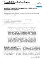
Jovanov, E., Milenkovic, A., Otto, C., de Groen, P. (2005). A wireless body area network of
intelligent motion sensors for computer assisted physical rehabilitation. Journal of
NeuroEngineering and Rehabilitation, March, pp.2-6.
Juanola, E., Miribel-Català, P., Colomer-Fararrons, J., & Samitier, J. (2010). New green
market opportunities from novel autonomous low power systems by energy
harvesting. XXVII World Conference on Science and Technology Parks, IASP1020,
Kakerow, R., Kappert, H., Spiegel, E., and Manoli, Y. (1995). Low-power single-chip CMOS
potentiostat. Proc. of the International Conference on Solid-State Sensors and Actuators.
Katz, E., and Willner, I. (2003). Probing biomolecular interactions at conductive and
semiconductive surfaces by impedance spectroscopy: routes to impedimetric
immunosensors. DNA-sensors, and enzyme biosensors. Electroanalysis, vol. 15, pp.
913–947.
Kazazian T., and Jansen, A.J. (2004). Eco-desing and human-powered products. Proceedings
of the Electronics Goes Green 2004, 6-10 September 2004.
Khaligh, A., Zeng P., Xiaochun, W., and Yang, X. (2008). A hybrid energy scavenging
topology for human-powered mobile electronics. Proc. of the 34th Annual Conference
of IEEE Industrial Electronics, Nov. 2008 pp. 448 - 453.
Khaligh, A., Zheng, P., and Zheng, C. (2010). Kinetic Energy Harvesting Using Piezoelectric
and Electromagnetic Technologies-State of the Art. IEEE Transactions on Industrial
Electronics, vol.57, no. 3, March 2010, pp. 850-860.
New Perspectives in Biosensors Technology and Applications
398
Kissinger, P., Preddy, C., et.al. (1996). Laboratory Techniques in Electroanalytical Chemistry.
Second Edition, P. Kissinger, and W. Heineman Eds., Marcel Dekker, Inc.,ISBN: 0-
8247-9445-1, New York.
Kitamori, K. (2007). Micro and Nano Chemical System on Chip. Proc. of the International
Solid-State Sensors, Actuators and Microsystems Conference, pp. 11 – 16
Kiziroglou, M.E., He, C., and Yeatman, E.M. (2009). Rolling Rod Electrostatic
Microgenerator. IEEE Transactions on Industrial Electronics, vol. 56, no. 4, pp. 1101 –
1108.
Kramer,D.L. (1987). Dissolved oxygen and fish behavior. Environmental Biology of Fishes,
vol.18, pp. 81-92 .
Kraver, K., Guthaus, M., Strong, T., Bird, P., Cha, G., Hold, W., and Brown, R. (2001). A
mixed-signal sensor interface microinstrument. Sensors and Actuators A, vol. 91, pp.
266-277.
Kros, A., Van Hovell, W.F.M, Sommerdijk, N.A.J.M., and Nolte, R.J.M. (2001). Poly(3, 4-
thylenedioxythiophene)-based glucose biosensors. Adv. Mater, vol. 13, pp. 1555–
1557.
Laureyn, W., Nelis, D., Van Gerwen, P., Baert, K., Hermans, L., Magnee, R., Pireaux, J.J., and
Maes, G. (2000). Nanoscaled interdigitated titanium electrodes for impedimetric
biosensing. Sens. Actuators B-Chem, vol. 68, pp. 360–370
Le, T.T., Han, J., Jouanne, A. Von., Mayaram, K., and Fiez, T.S. (2006). Piezoelectric Micro-
Power Generation Interface Circuits. IEEE Journal of Solid-State Circuits, vol.41, no.6,
pp. 1411-1420, June 2006.
Lee, Y.J., Kim, J.D., Park, J.Y., (2009). Flexible enzyme free glucose micro-sensor for
continuous monitoring applications. Proc. Of the Solid-State Sensors, Actuators and
Microsystems Conference, 2009, pp. 1806 - 1809
Li, W., He, S., and Yu, S. (2010). Improving Power Density of a Cantilever Piezoelectric
Power Harvester Through a Curved L-Shape Proof Mass. IEEE Transactions on
Industrial Electronics, vol.57, no.3, pp. 868-876.
Lillie, G., Payne, P., and Vadgama, P. (2001). Electrochemical impedance spectroscopy as a
platform for reagentless bioaffinity sensing. Sens. Actuators B-Chem, vol. 78, pp. 249–
256.
Liu, Y., Chakrabartty, S., and Alocilja. E.C. (2007). Fundamental building blocks for
molecular biowire based forward error-correcting biosensors. Nanotechnology, vol.
18, 424017, pp. 1-6.
Mohseni, P., Najafi, K., Eliades, S.J., Xiaoqin Wang, (2005). Wireless multichannel
biopotential recording using an integrated FM telemetry circuit. IEEE Tran. on
Neural Systems and Rehabilitation Engineering, vol. 13, issue 3, pp. 263-271
Murari, K., Sauer, C.M., Stanacevic, M., Cauwenberghs, G., and Thakor, N. (2005). Wireless
Multichannel Integrated Potentiostat for Distributed Neurotransmitter Sensing.
Prof. Of the Engineering in Medicine and Biology Conference.
Myung-suk, C., Sang-won, L., Jong-chul, K., Jun-dong, C., Jin-kwon, K., Hang-sik. S.,
Myung-ho, L., Un-sun, C., and Jae-seok, K. (2007). Implantable Bio system design
for displacement measurement of living life. Proc. of the International Conference on
Advanced Communication Technology, vol. 1, pp.299 – 304
Nasiri, A., Zabalawi, S.A., and Mandic, G. (2009). Indoor Power Harvesting Using
Photovoltaic Cells for Low-Power Applications. IEEE Transactions on Industrial
Electronics, vol. 56, no. 11, pp. 4502 – 4509.
Portable Bio-Devices:
Design of Electrochemical Instruments from Miniaturized to Implantable Devices
399
Niyato, D., Hossain, E., Rashid, M.M., and Bhargava, V.K. (2007).Wireless sensor networks
with energy harvesting technologies: a game-theoretic approach to optimal energy
management. IEEE Wireless Communications, vol.14, no. 4, pp.90-96.
Paradiso, J.A. Starner, T. (2005). Energy scavenging for mobile and wireless electronics. IEEE
Pervasive Computing, vol.4, Issue 1, pp. 18-27.
Patel, J.N., Kaminska, B., Gray, B., Gates, B.D. (2007). Electro-Enzymatic Glucose Sensor
Using Hybrid Polymer Fabrication Process. Proc. Of IEEE International Conference the
Electronics, Circuits and Systems, 2007. ICECS 2007, pp. 403 – 406
Poyatos, J.M., Muñio, M.M., Almecija, M.C., Toress, J.C., Hontoria, E., and Osorio.F. (2010).
Advanced Oxidation Processes for Wastewater Treatment: State of the Art. Water
Air Soil Pollut, vol.205, pp. 187-204.
Rahman, A.R.A., Justin, G., Guiseppi-Wilson, A., Guiseppi-Elie, A., (2009). Fabrication and
Packaging of a Dual Sensing Electrochemical Biotransducer for Glucose and Lactate
Useful in Intramuscular Physiologic Status Monitoring. Sensors Journal, vol. 9, issue
12, pp. 1856 – 1863
Reay, R., Kounaves, S., and Kovacs, G. (1994). An integrated CMOS potentiostat for
miniaturized electroanalytical instrumentation. Proc. of the IEEE Solid-State Circuits
Conf.
Rodrigues, N.P., Kimura, H., Sakai, Y., Fujii, T. (2007). Cell-Based Microfluidic Biochip for
Electrochemical Real-Time Monitoring of Glucose and Oxygen. Proc. Of the Solid-
State Sensors, Actuators and Microsystems Conference, pp. 843 - 846
Rodríguez-Trujillo, R., Castillo-Fernandez, O., Garrido, M., Arundell, M., Valencia, A.,
Gomila, G. (2008). High-Speed particle detection in a micro-Coulter counter with
two-dimensional adjustable aperture. Biosensors and Bioelectronics. vol 24:2, pp. 290-
296
Rodríguez-Villarrea, A.I., Arundell, M., Carmona, M., Samitier, J. (2010) -High flow rate
microfluidic device for blood plasma separation using a range of temperaturas. Lab
on a Chip, vol 10, pp. 211-219.
Roundy, S. Steingart,D., Frechette, L., Wright, P., and Rabaey, J. (2004). Power sources for
wireless sensors networks. Proc. of the 1st European Workshop on Wireless Sensors
Networks, Jan.2004, pp. 1-17.
Sato, F., Togo, M., Islam, MK., Matsue, T., Kosuge, J., et al. (2005). Enzymebased glucose fuel
cell using Vitamin K-3-immobilized polymer as an electron mediator.
Electrochemistry Communications, vol.7, no.7, pp. 643-647.
Shenck, N.S., and Paradiso, J. (2001). Energy scavenging with shoe-mounted piezoelectrics.
IEEE Micro, Vol. 21, No. 3, May-June 2001, pp. 30-42.
Sogorb, T., Llario, J.V., Pelegri, J., Lajara, R., and Alberola, J. (2008).Studying the Feasibility
of Energy Harvesting from Broadcast RF Station for WSN. Proc. of the IEEE
Instrumentation and Measurement Technology Conference, May 2008, pp. 1360 – 1363.
Stark, J. (2006). Thermal Energy Harvesting with Thermo Life. Proc. of the International
Workshop on Wearable and Implantable Body Sensor Networks, pp.19 – 22.
Teymoori, M.M., Asadollahi, H. (2009). MEMS Based Medical Microsensors. Proc. Of the
Computer and Electrical Engineering International Conference, vol. 1, pp.158 – 162.
Terbouche, A., Djebbar, S., Benali-Baitich, O., and Hauchard, D. (2011). Complexation Study
of Humic Acids Extracted from Sahara Soils with Zuinc (II) and Cadmium (II) by
Differential Pulse Anodic Stripping Voltammetry (DPASV) and Conductimetric
Methods. Water Air Soil Pollut, vol.216, pp. 679-691.
New Perspectives in Biosensors Technology and Applications
400
Thewes, R., Hofmann, F., Frey, A., Holzapfl, B., Schienle, M., Paulus, C., Schindler,P.,
Eckstein, G., Kassel, C., Stanzel, M., Hintsche, R., Nebling, E., Albers, J., Hassman,
J., Schülein, J., Goemann, W., and Gumbrecht, W. (2002). Sensor Arrays for Fully-
Electronic DNA Detection on CMOS. Proc. Of the IEEE International Solid-State
Circuits Conference.
Usman Ali, S.M., Nur, O., Willander, M., Danielsson, B. (2009). Glucose Detection With a
Commercial MOSFET Using a ZnO Nanowires Extended Gate. IEEE Transactions on
Nanotechnology, vol. 8, issue 6, pp. 678 – 683.
Van Hoof, C., Leonov, V., Vullers, R.J.M. (2009). Thermoelectric and Hybrid Generators in
Wearable Devices and Clothes. Sixth International Workshop on Wearable and
Implantable Body Sensor Networks. 3-5 June, pp. 195 – 200.
Part 3
Biosensors for Environment and Biosecurity
19
Carbon Nanotube-based
Cholinesterase Biosensors for the
Detection of Pesticides
Xiuli Yue and Zhifei Dai
Nanomedicine and Biosensor Laboratory, School of Sciences,
State Key Laboratory of Urban Water Resources and Environment,
Harbin Institute of Technology, Harbin 150001,
China
1. Introduction
Pesticides play an important role in the high productivity achieved in agriculture through
the control of pests. However, the presence of pesticide residues and metabolites in food,
water and soil currently represents one of the major issues for the environmental
chemistry(Ongley, 1996; Smith and Gangolli, 2002; Lintellman et al., 2003). Pesticides are
often very persistent with half-lives of decades and are transported over long distances by
global circulation, and through run-off, find their way into aquatic systems. They are
intentionally toxic, often towards non-target organisms. Three classes of pesticides have
been problematic, namely organophosphates, carbamates and organochlorines.
Organophosphate(OPs) pesticides obtain their toxicity from their ability to inhibit
acetylcholinesterase (AChE), causing neurotoxicity (Fukuto, 1990). The presence of this
enzyme in insects, birds, fish and all mammals give this class of pesticides enormous
toxicity towards unintended targets. Carbamate pesticides are also cholinesterase inhibitors
with a similar mechanism of action as organophosphate pesticides (Fukuto, 1990). An
effective strategy for dealing with pesticide contamination in the environment has to
commence with an assessment of the extent of the problem. Traditionally, chromatographic
methods have been used to analyze the presence of compounds in environmental samples.
These techniques are very powerful tools for monitoring toxic pesticides, but, they are
expensive, time-consuming (involve extensive preparation steps), are not adapted for in situ
and real time detection and require highly trained personnel. They are therefore unsuitable
for screening of large volumes of samples, and due to their cost, developing countries do not
readily have access to such methods.
Biosensors has attracted intensive research interest as a result of the need for cheap, fast and
easy to use analytical tools that are able to provide real-time qualitative and quantitative
information about the composition of a sample with minimum sample preparation (Dyk
and Pletschke, 2011). Biosensors are analytical devices which utilize the sensitivity and
selectivity of a bio-receptor attached onto the surface of a physical transducer. The
cholinesterase (ChE) enzymes based biosensors have emerged as an ultrasensitive and
selective technique for toxicity monitoring for environmental, agricultural, food or military
New Perspectives in Biosensors Technology and Applications
404
applications (Silvana and Marty, 2006). These devices are based on the inhibition of ChE by
toxicants such as pesticides. The principal motivation for designing ChE biosensors for
toxicity monitoring is to provide a reliable alternative to classical methods currently used in
chromatographic methods. A successful ChE biosensor for toxicity monitoring should offer
comparable or even better analytical performances than the traditional chromatographic
systems. Ideally, such sensors should be small, cheap, simple to handle and able to provide
reliable information in real-time without or with a minimum sample preparation. The use of
the enzyme should also provide increased sensitivity and selectivity for the analyte of
interest.
Electrochemical biosensors are currently among the most popular of the various types of
biosensors. Carbon nanotubes (CNTs) are promising materials for sensing applications due
to fascinating electronic and optoelectronic properties that are distinct from other
carbonaceous materials and nanoparticles of other types (Balasubramanian and Burghard,
2006). Particularly, the properties of small dimensions, functional surfaces, good
conductivity, excellent biocompatibility, modifiable sidewall, and high reactivity make
CNTs have some overwhelming advantages in fabricating electrochemical sensors with high
performances (Rivas et al, 2007). Moreover, CNTs have an outstanding ability to mediate
fast electron-transfer kinetics for a wide range of electroactive species, such as AChE. CNT
chemical functionalization can be used to attach almost any desired chemical species to
them, which allows us to enhance the solubility and biocompatibility of the tubes. This has
permitted the realization of composite electrodes comprising CNTs well-dispersed in an
appropriate polymer matrix(Wang et al, 2003).
Generally, the replacement of ordinary materials by CNTs can effectively improve the redox
currents of inorganic molecules, organic compounds, macrobiomolecules or even biological
cells. Due to the well-defined structure, the chemistry stability and the electrocatalytic
activity toward many substances, CNTs are also extensively used as the carrier platforms for
constructing various electrochemical sensors. Herein, we present an overview of significant
advances in the research and development of CNT-based ChE biosensors. We will discuss
the different configurations and fabrication techniques of CNT-based biosensors with a
special emphasis on the low-cost electrochemical biosensors and the approaches used for
enzyme immobilization.
2. Inhibitory effect of pesticides on Cholinesterase
Many enzymes used for the detection of pesticides are inhibited by the pesticide and the
extent of inhibition is correlated to the concentration of the analyte. Acetylcholinesterases
are a class of enzymes that catalyze the hydrolysis of acetylcholine, an ester which is a
neurotransmitter (Fukuto, 1990; Stenersen, 2004). The reaction catalyzed by AChE is:
acetylcholine+H
2
O→choline+acetate. Organophosphate and carbamate pesticides are
designed to inhibit AChE and this enzyme has been mostly used in enzymatic detection of
these pesticides. The inhibition of AChE by organophosphates takes place as a result of the
phosphorylation of the serine residue in the active site of the enzyme. The hydroxyl group
on the serine residue acts as an electrophile which attacks the nucleophilic phosphorus. The
phosphorylated enzyme is highly stable and the hydrolysis of acetylcholine is blocked. In
some cases, depending on the chemical structure of the pesticide, the phosphorylation, and
thus the inhibition, may be irreversible (Fukuto, 1990). Where the pesticide is a
Carbon Nanotube-based Cholinesterase Biosensors for the Detection of Pesticides
405
phosphorothionate ester with a P=S moiety rather that a P=O, these pesticides generally act
as poor cholinesterase inhibitors, due to the low reactivity of the compound (Fukuto, 1990).
An example of two phosphorothionate ester compounds is malathion or chloropyrifos. It
would be expected that these compounds would be poor cholinesterase inhibitors. This can
be overcome by chemically oxidizing the phosphorothionate ester compounds into its more
active form prior to detection (Lee et al., 2002).
It is helpful for the development of a biosensor based on enzyme inhibition to know the
structure of ChE enzyme and the mechanism of inhibition in order to better optimize several
parameters which affect the degree of inhibition such as enzyme loading, incubation time,
reaction time, concentration of substrate, pH and organic solvent (Arduini, 2010). The
principal biological role of AChE is the termination of the nervous impulse transmission at
cholinergic synapses by rapid hydrolysis of the neurotransmitter acetylcholine. Early kinetic
studies indicated that the active site of AChE contains two sub-sites, the esteratic and
anionic sub-sites, corresponding respectively, to the catalytic site and choline-binding
pocket (Gordon, 1976). The esteratic site contains a serine residue which reacts with the
substrate and, also, with the organophosphates and carbamates. This site is similar in the
multiple forms of AChE (Electrophorus, Torpedo, rat and chicken) and it is also located in
the butyrylcholinesterase (BChE) enzyme. For this reason, it is possible to use several
species of AChE and BChE enzymes to develop a ChE biosensor for insecticides.
The substrate concentration can affect the degree of inhibition. It was found that the
inhibition level (%) increases with increasing of the substrate concentration in the case of
pesticide inhibition when a saturating substrate concentration was used (Kok et al, 2002).
Joshi et al. (2005) have used a concentration of acetylhtiocholine two times higher than the
apparent Michaelis–Menten constant (K
m
) for the determination of the maximum activity of
AChE before and after the inhibition by the paraoxon which was selected as model
pesticide. In the case of competitive inhibition, at high substrate concentrations, the
inhibition effect is not observed since the substrate competes with the inhibitor. Another
enzyme that is related to AChE is BChE which is also termed pseudocholinesterase
(Andreescu and Marty, 2006). Both these enzymes have been used for the detection of
pesticides in the environment, but use different substrates. AChE and BChE also differ in
that AChE is inhibited by excess substrate whereas BChE is not. In the case of irreversible
inhibition, the high substrate concentration can be chosen in order to have a higher output
signal. For AChE biosensor a concentration of 1 mM acetylthiocholine was adopted
(Arduini, 2006). In order to obtain higher sensitivity in the case of biosensor format for
insecticides, acetylcholine or acetylthiocholine for AChE biosensor and butyrylcholine or
butyrylthiocholine for BChE biosensor is highly suggested (Arkhypova, 2004).
For irreversible inhibition it is possible to achieve lower detection limits using longer
incubation times; in fact, usually the degree of the enzyme inhibition increases with the
incubation time until reaching a plateau (Kok, 2004). The incubation time is usually chosen
as compromise between a sensitive measurement and a measurement carried out in a
reasonable time (Dzyadevych, 2005). Usually, the incubation time should be not longer than
1 h because one of the biosensor advantage than i.e. HPLC should be the short time of
analysis. In order to increase the sensitivity of the biosensor, it is better varying the enzyme
loading than to use the incubation time longer than 1 h. In fact, for irreversible inhibition the
degree of inhibition depends of the enzyme concentration.
The pH of the solutions containing substrates can affect the overall enzymatic activity since,
like all natural proteins, enzymes have a native tertiary structure that is sensitive to pH;