Organic Light Emitting Diode Material Process and Devices Part 9 pptx
Bạn đang xem bản rút gọn của tài liệu. Xem và tải ngay bản đầy đủ của tài liệu tại đây (3.33 MB, 25 trang )
Organic Light Emitting Diodes Based on Novel Zn and Al Complexes
191
Schlatmann A., Floet D., Hilberer A., Garten F., Smulders P, Klapwijk T., and Hadziioannou G.
(1996), Indium contamination from the indium–tin–oxide electrode in polymer light
emitting diodes, Appl. Phys. Lett., Vol. 69, No 12, pp. 1764-1767 ISSN 0003-6951.
Sheats J., Antoniadis H., Hueschen M., Leonard W., Miller J., Moon R., Roitman D., and
Stocking A. (1996), Organic electroluminescent devices, Science, Vol. 273, No 5277,
pp. 884 -888,
ISSN: 00368075
Shi J. and Tang C. (1997), Doped organic electroluminescent devices with improved
stability, Appl. Phys. Lett., Vol. 70, No 13, pp.1665-1667, ISSN: 0021-8979.
Shi Y., Deng Zh, Xu D., and Xiao J. (2006), Organic light-emitting diodes with improved
hole–electron balance and tunable light emission with aromatic
diamine/bathocuproine multiple hole-trapping-layer, Displays, Vol 27, No 4-5, pp.
166-169, ISSN: 0141-9382.
Shukla V. and Kumar S. (2010), Conversion of a green light emitting zinc-quinolate complex
thin film to a stable and highly packed blue emitter film, Synthetic Metals, Vol. 160,
No 5-6, pp. 450–454, ISSN: 0379-6779.
Tang C. and VanSlyke S. (1987), Organic electroluminescent diodes, Appl. Phys. Lett. Vol. 51,
No 12, pp. 913-915, ISSN: 0003-6951.
Tadayyon S., Grandin H., Griffiths K., Norton P., Aziz H., and Popovic Z. (2004), CuPc
buffer layer role in OLED performance: a study of the interfacial band energies,
Organic Electronics, Vol. 5, No 4, pp. 157–166, ISSN: 1566-1199.
Tokito S., Noda K., Tanaka H., Taga T., and Tsutsi T., Organic light-emitting diodes using
novel metal–chelate complexes, Syn. Met., Vol. 111-112, No 1, pp. 393-397, (2000)
ISSN: 0379-6779.
Tomova R., Petrova P., Buroff A., and Stoycheva-Topalova R. (2007), Organic light-emitting
diodes (OLEDs) – the basis of next generation light-emitting dеvices, Bulgarian
Chemical Communications, Vol. 39, No 4, pp. 247 -259, ISSN: 0324-1130.
Tomova R., Petrova P., Stoycheva-Topalova R, Buroff A., Vassilev A., and, Deligeorgiev T.
(2008), Bathocuproine as Hole-blocking and Electron-transporting Layer in Organic
Light Emitting Devices, Nanoscience& Nanotechnology - Proceedings of the 9
th
Workshop
Nanostructured Materials Application and Inovation Transfer, November 28-30, 2007,
Sofia, Bulgaria, eds. E.Balabanova, I.Dragieva, Pub by Prof. Marin DrinovAcademic
Publishing House, Sofia, pp. 114-117, ISBN: 978-954-322-286-5.
Tomova R., Petrova P., Kaloianova S., Deligeorgiev T., Stoycheva-Topalova R., and Buroff
A. (2008), Organic Light Emitting Devices Based on Novel Zn Complexes,
Proceedings of 14th Int. Workshop on Inorganic and Organic Electroluminescence & 2008
Int. Conference on the Science and Technology of Emissive Displays and Lighting (EL
2008), Italy 9-12 September 2008, pp. 69-73
Tomova R., Petrova P., and Stoycheva-Topalova R. (2010), Role of bathocuproine as hole-
blocking and electron-transporting layer in organic light emitting devices, Phys.
Status Solidi C, Vol 7, No. 3–4, pp. 992–995, ISSN : 1610-1634
Troadec D., Veriot G. and Moliton A. (2002), Simulation study of the influence of polymer
modified anodes on organic LED performance, Synthetic Metals, Vol. 127, No 2,
pp.165-175, ISSN: 0379-6779.
Tripathi V., Datta D., Samal G., Awasthi A., and Kumar S. (2008), Role of exciton blocking
layers in improving efficiency of copper phthalocyanine based organic solar cells, J.
of Non-Crystalline Solids, Vol. 354, No 19-25, pp. 2901- 2904, ISSN: 0022-3093.
Organic Light Emitting Diode – Material, Process and Devices
192
Van Slyke S., Chen C., and Tang C. (1996), Organic electroluminescent devices with
improved stability, Appl. Phys. Lett., Vol. 69, No 15, pp. 2160-2163, ISSN: 0021-8979.
Wang H., Wang L., Wu Z., Zhang D., Qiao J., Qiu Y., and Wang X. (2006), Efficient single-
active-layer organic light-emitting diodes with fluoropolymer buffer layers, Appl.
Phys. Lett., Vol. 88, No 13,131113, ISSN: 0021-8979.
Wang Y., Teng F., Zhou Q., and Wang Y. (2006), Multiple roles of bathocuproine employed
as a buffer-layer in organic light-emitting diodes, Applied Surface Science, Vol. 252,
No 6, pp. 2355-2359, ISSN: 0169-4332.
Wei X., Yang G, Cheng J., Lu Z., and Xie M. (2007), Synthesis of novel light emitting
calix[4]arene derivatives and their luminescent properties, Mat. Chem. Phys., Vol.
102, No 2-3, pp. 214-218, ISSN: 0254-0584.
Wu J., Hou J., Cheng Y, Xie Z., and Wang L. (2007), Efficient top-emitting organic light-
emitting diodes with a V
2
O
5
modified silver anode, Semicond. Sci. Technol., Vol. 22,
No 7, pp. 824-828, ISSN: 0268-1242.
Wu X., Hua Y., Wang Z., Zheng J., Feng X. and Sun Y. (2005), White Organic Light-Emitting
Devices Based on 2-(2-Hydroxyphenyl) Benzothiazole and Its Chelate Metal
Complex, Chinese Phys. Lett., Vol 22, No 7, pp. 1797-1799, ISSN: 1741-3540.
Wu Z., Yang H., Duan Y., Xie W., Liu S., and Zhao Y. (2003), Improved efficiency of organic
light-emitting devices employing bathocuproine doped in the electron-transporting
layer, Semicond. Sci. Technol., Vol. 18, L49–L52, ISSN 0268-1242.
Xu B., Chen L., Liu X., Zhou H., Xu H., Fang X., and Wang Y. (2008), Mixed ligands 8-
hydroxyquinoline aluminum complex with high electron mobility for organic light-
emitting diodes, Appl. Phys. Let., Vol. 92, No 10, 103305, ISSN: 0021-8979.
Xu X., Yu G., Liu Y.,and Zhu D. (2006), Electrode modification in organic light-emitting
diodes, Displays, Vol. 27, No 1, pp. 24-34, ISSN: 0141-9382.
You H.,. Dai Y, Zhang Z., and Ma D. (2007), Improved performances of organic light-
emitting diodes with metal oxide as anode buffer, J. Appl. Phys. Vol. 101, No 2, pp.
026105-026108), ISSN: 0034-6748.
Yu J., Li L., Jiang Y., Ji X., and Wang T. (2007), Luminescent Enhancement of Heterostructure
Organic Light-Emitting Devices Based on Aluminum Quinolines, J. Electr. Sci.
Techn. of China, Vol. 5, No 2, pp. 183-186, ISSN : 1674 862X.
Zhang Y., Cheng G., Zhao Y., Hou J., and Liu Sh. (2005), White organic light-emitting
devices based on 4,4′-bis(2,2′-diphenyl vinyl)-1,1′-biphenyl and phosphorescence
sensitized 5,6,11,12-tetraphenylnaphthacene, Appl. Phys. Lett., Vol 86, No 1, 011112,
ISSN: 0003-6951
Zheng J., Hua Y., Yin S.,. Feng X, Wu X., Sun Y., Li Y., Yang Ch. and Shuai Z. (2005), White
organic light-emitting devices using Zn(BTZ)2 doped with Rubrene as emitting
layer, Chinese Science Bulletin, Vol. 50, No 6, pp. 509-513, ISSN: 1001-6538.
Zheng X., Wu Y., Sun R., Zhu W., Jiang X., Zhang Z., and Xu S., (2005), Efficiency
improvement of organic light-emitting diodes using 8-hydroxy-quinolinato lithium
as an electron injection layer, Thin Solid Films , Vol. 478. No 1-2, pp.252-255, ISSN:
0040-6090.
Zhu F., Hua Y., Yin S., Deng J., Wu K., Niu X., Wu X. and Petty M. (2007), Effect of the
thickness of Zn(BTZ)
2
emitting layer on the electroluminescent spectra of white
organic light-emitting diodes, J. Luminescence, Vol. 122-123, pp. 717-719, ISSN: 0022-
2313.
Part 2
OLED Processes and Devices
7
Unconventional, Laser Based OLED Material
Direct Patterning and Transfer Method
Seung Hwan Ko
1
and Costas P. Grigoropoulos
2
1
Applied Nano Tech and Science Lab, Department of Mechanical Engineering
Korea Advanced Institute of Science and Technology, (KAIST), Daejeon
2
Laser Thermal Lab, Department of Mechanical Engineering, University of California
Berkeley, California
1
Korea
2
USA
1. Introduction
Organic light emitting diode (OLED) displays have a number of desirable features such as
high contrast and brightness, wide color range, thin structure and light weight, among
others.(Hirano et al. 2007) OLED displays have several manufacturing requirements such as
large area scalability and an increasing push towards smaller feature sizes, tighter feature
shape control, high yield and low cost. However, traditional lithography and thermal
evaporation deposition techniques have significant disadvantages, including the need for
masks that are typically difficult to make to the required specifications at a reasonable price.
The conventional vacuum deposition and photolithographic patterning methods are well
developed for inorganic microelectronics. However, organic electronics materials are
chemically incompatible with corrosive etchants, resists and developers used in
conventional integrated circuit (IC) processing. In practice, conventional IC fabrication
processes are subject to limitations, in that they are multi-step, involve high processing
temperatures, toxic waste and are therefore expensive. Furthermore, the increasing size of
electronic devices such as displays poses great difficulty in adapting standard
microfabrication processes, including lithographic patterning. (Zschieschang et al. 2003,
Ko et al. 2007)
Therefore, there is a strong need to develop a novel process instead of complex modification
of conventional vacuum deposition and photolithography based processes. OLED display
manufacturing employs direct write techniques for patterning the various materials.
Examples of OLED material direct write technologies include ink jet printing (Hashimoto et
al, 2006, Gohda et al. 2002, Lee et al. 2002,, Kobayshi et al. 2002, Shirasaki et al. 2004, Fleuster
et al. 2004, Lee et al. 2005, Saafir et al. 2005) screen printing (Shinar et al. 2007, Lee et al.
2009) and laser induced forward transfer (LIFT) (Hirano et al. 2007, Piqué et al. 1999, Suh et
al. 2003, Willis et al. 2005, Kyrkis et al. 2006). As described in a recent review on OLED RGB
patterning, success of an OLED patterning scheme depends on the material type, device
design, pixel array pattern, display format, substrate size, placement accuracy, process
TACT-time, and defect density. The type of material and OLED architecture largely
determine which type of RGB patterning can be applied. Other factors determining the
Organic Light Emitting Diode – Material, Process and Devices
196
viability of the patterning method for active matrix organic light emitting diode
(AMOLEDs) depend on the given material set. (Lamansky et al. 2005) Solution processible
direct write technologies such as inkjet printing and screen printing are subject to a number
of limitations such as the need for solvent removal and contamination into the deposited
material. Additionally, the minimum feature size is heavily influenced by the properties of
the fluid used to deliver the material of interest and multilayer structure fabrication is
difficult. (Kyrkis et al. 2006) Vacuum-processable OLEDs have been patterned mostly by
deposition through a shadow mask or fine-metal mask (FMM). (Kang et al. 2003) Deposition
can be accomplished either as a conventional physical evaporation or organic vapour phase
deposition (OVPD), but FMM-related patterning issues are largely independent of the
deposition technique. Remaining FMM patterning issues include difficulty of fabricating
high resolution masks for large-area displays, mask lifetime and cleaning, particle
contamination, and thermal expansion effects.
In this chapter, unconventional OLED material direct patterning and transfer methods
especially laser based forward transfer and patterning approaches will be presented as
promising potential alternative to conventional OLED fabrication methods.
Fig. 1. 14 inch OLED display from CDT (Cambridge Display Technology) from CDT ltd.
2. OLED material laser induced forward transfer and patterning techniques
LIFT techniques pattern and transfer materials of interest by laser induced localized thermal
evaporation or chemical decomposition of dynamic release layer. This dynamic release layer
is the crucial part of the LIFT process and can be (a) a part of material of interest, (b)
specially designed light absorbing thin intermediate layers in LITI (laser induced thermal
imaging) (Lamansky et al. 2005, Blanchet et al. 2003a, Suh et al. 2003) and LIPS (laser
Unconventional, Laser Based OLED Material Direct Patterning and Transfer Method
197
induced pattern-wise sublimation) process (Hirano et al. 2007) or (c) a mixture of active or
sensitive material in a UV absorbent matrix in MAPLE DW(matrix assisted pulsed laser
evaporation direct writing) (Piqué et al. 1999, Arnold et al. 2007) process. LIFT and several
variations have demonstrated deposition of metals, metal oxide films, inorganic dielectric
films, ceramics, and polymer and biomaterials. (Arnold et al. 2007, Willis et al. 2005, Kyrkis
et al. 2006, Chrisey et al. 2003) Most notable recent advance in LIFT technique is the OLED
pixel fabrication using dialkyltriazene polymer as an UV-absorbing and decomposing
intermediate sacrificial layer compared with thermal decomposition. (Rardel et al. 2007)
However, most LIFT based techniques in OLED material transfer process still exhibit a
number of limitations such as laser selection (wavelength, fluence), resolution, and edge
sharpness. Most LIFT based techniques apply ultraviolet (UV) or infrared (IR) laser with
relatively high laser fluences (1~10 J/cm
2
) to obtain enough pressure for ablative material
transfer. UV or IR lasers need complex and expensive laser and optic system. Furthermore,
without strict design of light absorbing layer, high power UV or IR lasers have high
possibility for organic material damage during the LIFT process because generally organic
materials have strong UV and IR absorption bands attributed to electronic and vibrational
transitions, respectively. Besides thermal degradation, high laser threshold laser can also
induce mechanical cracks on transfer material and problem in edge sharpness. Also
resolution was usually limited to 50 to 100 μm.
Ko et. al. reported a nanomaterial enabled laser transfer (NELT) to facilitate the high
resolution patterning and transfer of the heat-sensitive OLED material with more versatile
laser wavelength selection with one or two order smaller laser energy than conventional
LIFT processes. This is characterized by the introduction of an efficient light absorbing,
loosely connected nanomaterial layer and the choice of laser wavelength that although is
strongly absorbed by the properly engineered nanomaterial, it interacts only weakly with
the organic material of interest, leading to effective evaporation and transfer of the material
with less damage potential.
2.1 Laser Induced Thermal Imaging [LITI]
Over the last twelve years, we at 3M have developed Laser Induced Thermal Imaging (LITI)
as a high resolution, digital patterning technique with a large number of potential
applications including the patterning of digital color proofs, plates, and film; LCD color
filters, black matrix, and spacers; field emission display (FED) anodes, contrast enhancement
filters, and nanoemitters; organic field effect transistor (OFET) fabrication; and OLED
emitters, color filters, and color conversion filters. Since 2000, 3M has partnered with
Samsung SDI to jointly develop the process for AMOLEDs. (Wolk et al, 2004)
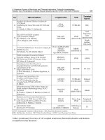
LITI involves the use of a precoated donor film, a large format laser exposure system, and a
receptor (e.g. an AMOLED backplane) (Fig. 2). For OLEDs, a stock roll of functional non-
transferring layers is prepared and stored. Solvent coating or vapor deposition is used to
deposit an ultrathin (e.g. 20-200 nm) layer of red, green, or blue emitting transfer layer(s) to
the stock roll shortly before patterning. Patterning of each color is then accomplished by first
aligning the receptor (e.g. an AMOLED backplane) to the laser exposure system and then
laminating a donor film to the aligned receptor. After the alignment step, the laser system is
used to expose the laminated assembly. Exposed regions are released from the donor and
adhered to the receptor. The process is repeated from two or more times, depending upon
the OLED construction. Alignment is performed only once. (Wolk et al, 2004)
Organic Light Emitting Diode – Material, Process and Devices
198
Once a donor is used to pattern OLED materials, it is discarded. Although the transferred
area represents less than a third of the coated surface, the exposed donor film now contains
a high resolution pattern. Dimensional instability of the film and the physical changes that
the film undergoes during the exposure process make it impractical to reuse the exposed
donor. (Wolk et al, 2004)
3M’s LITI Process is well suited for use in the manufacture of high precision flat panel
displays, where high resolution, absolute placement accuracy, and large format imaging are
all required. The advantages of the LITI process are significant in situations where the
separation of coating and patterning steps resolves a fundamental process. LITI applications
include patterning of organic electronic materials for OLEDs and organic transistors,
patterning of multilayered OLED stacks, patterning of polarizers or nano-emitters, and the
potential of patterning enzymes and other biomaterials. (Wolk et al, 2004)
Fig. 2. LITI process schematics. (Blanchet et al. 2003b)
LITI is an emerging technology for high-resolution patterning of materials, including but
not exclusive to both solution- and vacuum-processable OLED material sets. (Lamansky et
al. 2005) Base steps in the LITI process include deposition of the material to be patterned
(transfer material) onto a specially designed donor film, precise optical alignment of a large
format laser imaging system to device substrate (receptor) fiducials, lamination of the donor
onto the substrate, and patterning of the transfer material onto the substrate by selective
exposure of the donor-transfer material-receptor stack to laser radiation. Conversion of laser
radiation to heat is achieved in a light-to-heat conversion (LTHC) layer(s), which typically
utilizes carbon black as a black body absorber. To generate a patterned RGB OLED display,
optical alignment is performed only once, but lamination and exposure have to be
performed for at least two colors.
Unconventional, Laser Based OLED Material Direct Patterning and Transfer Method
199
Advantages of LITI over other patterning methods include its applicability to a broad
spectrum of OLED material sets, high patterning accuracy (±2-5 μm compared to ±15-20 μm
for shadowmasking and ink-jet techniques), ability to pattern multilayer structures in a
single step, scalability of the process to large mother glass sizes, and ability to meet TACT
time requirements. It is possible that LITI introduces thermal defects in the OLED materials
during patterning, but by fine-tuning process conditions, donor structure, and OLED
composition, occurrence of such defects can be minimized. The process is also sensitive to
particulates and similar contamination of substrate (receptor in LITI terms) and donor
surfaces. This puts stringent requirements on the donor, substrate and transfer atmosphere
cleanliness.
2.2 Laser Induced Patternwise Sublimation [LIPS]
White OLED with color filter (WOLED+CF) methods and thermal transfer technologies are
expected as alternatives to precision mask patterning. Sony demonstrated the WOLED+CF
prototype display at SID 2003 (Kashiwabara et al. 2004). However, high power consumption
and color impurity are the issues of this method for the TV application. Laser-induced
thermal imaging (LITI) (Lee et al. 2004) and radiation-induced sublimation transfer (RIST)
(Boroson et al. 2005) have been proposed as thermal transfer technologies. They have some
concerns in production process. In the LITI process, contact between the donor film and the
emitting area will degrade the device and transfer quality. Though RIST is a sublimation
process without the contact, OLED material will be damaged by gases (e.g. O
2
, H
2
O etc.)
released from a polyimide film donor during laser-heating. In addition, they require high
precision technique to set flexible film on a large scale glass substrate uniformly without
adhesive agents. Imprecise setting of a film donor lowers transfer performance. (Hirano
et al 2007)
Sony has proposed a novel laser transfer technology for manufacturing OLED displays.
Laser-induced pattern-wise sublimation (LIPS) has been developed to image RGB pixel
pattern. OLED materials are precisely patterned from glass donors to a substrate by a
scanning laser beam. The LIPS device performance is examined in comparison with
conventional evaporated devices. Using this technology, a 27.3-inch active matrix (AM)
OLED display has been fabricated. (Hirano et al 2007)
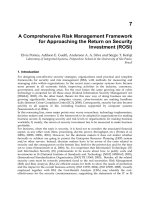
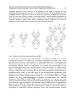
LIPS is a laser thermal transfer process. Two systems has been prepared, as shown in figure
3, in order to develop the LIPS process. One is the laser transfer system composed of
alignment equipment, a step-moving (X-axis) laser head and a scanning substrate stage (Y-
axis). The radiation source is an 800 nm diode laser. A width of the laser beam is adjusted in
accordance with that of the transferred pattern. The other is the vacuum chamber where a
glass donor is fixed on a substrate with clamping equipment. (Hirano et al 2007)
Figure 3 also shows the process flow diagrams of LIPS. A glass donor is necessary for each
emission layer (EML) to be patterned. Organic material is deposited in a conventional
evaporator on a glass donor covered with molybdenum absorption layer. Organic common
layers such as a hole injection layer (HIL) and a hole transport layer (HTL) are formed on
the glass substrate including a pixel defined layer (PDL) and bottom electrodes, as shown in
figure 1(d). The substrate and the glass donor are introduced without exposure to the air
and spaced apart in the vacuum chamber. And then the glass donor is put on the substrate
and fixed by the clamping equipment. It is moved out of the chamber onto the stage of the
laser transfer system in the atmosphere after introducing inert gas into the chamber. The
Organic Light Emitting Diode – Material, Process and Devices
200
transfer gap between the glass donor and the substrate is precisely controlled all over the
substrate by the rigid donor, the PDL and atmospheric pressure. Moreover the PDL
prevents the donor from contacting the emitting area on the substrate. After mechanical
alignment of the substrate to the laser head, laser beam scans and heats the designated
position of the glass donor and organic material is transferred to the substrate by vacuum
sublimation. The transferred organic material functions as an EML. The gap atmosphere is
kept vacuum by the clamping equipment during the laser transfer. The patterning process is
done for each emission layer. Common layers such as an electron transport layer (ETL) and
a top electrode are formed on the patterned substrate after removing the donor glass in inert
gas. (Hirano et al 2007)
From the viewpoint of productivity, the laser transfer process in the atmosphere can
simplify a production system and improve laser positioning accuracy. Multiplying laser
beams promise high throughput even for large-scale mother glass. Glass donors can be re-
cycled, which saves the production cost. (Hirano et al 2007)
Fig. 3. Schematic diagrams of the LIPS process. (a) Placement of the glass donor and the
substrate in the vacuum chamber (b) Setting of the glass donor on the substrate with
clamping equipment (c) Placement of the substrate on the laser transfer system (d) An
enlarged cross-section diagram of A in figure (c). (Hirano et al 2007)
The gap between a donor sheet and a substrate is critical to transfer accuracy. The advantage
of the LIPS process is high precision by use of a glass donor instead of a film donor. The
position accuracy is better than 4um. The pattern width variation is within ±2.0um. Using
the patterning accuracy, we can realize high aperture ratio more than 60% for large-sized
OLED display. The further improvement of patterning accuracy is possible by mechanical
adjustment. (Hirano et al 2007)
2.3 Matrix Assisted Pulsed Laser Evaporation – Direct Writing [MAPLE-DW]
MAPLE DW was originally developed as a method to rapidly prototype mesoscopic passive
electronic devices such as interconnects, resistors, and capacitors. (Piqué et al. 1999, Chrisey
et al. 2000) This technology falls under the category of a “direct-write” approach because, in
the same manner as a pen or pencil, it can be used to rapidly form any pattern with the aid
Unconventional, Laser Based OLED Material Direct Patterning and Transfer Method
201
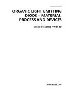
of CAD/CAM systems. The schematic of the apparatus is shown in figure 4. The material to
be transferred is mixed in a laser-absorbent matrix and coated onto a support, or ribbon,
that is transparent to the laser irradiation. A focused laser pulse is directed through the
backside of the ribbon so that the laser energy first interacts with the matrix at the ribbon
interface. The laser pulse is focused at the matrix-ribbon interface by a UV microscope
objective that also serves as an optical guide to determine the area of the matrix to transfer.
Layers of matrix near the support interface evaporate due to localized heating from
electronic and vibrational excitation. This sublimation releases the remaining material
further from the interface by gently and uniformly propelling it away from the quartz
support to a substrate positioned 25 μm to several mm away. By removing the ribbon and
allowing the laser pulse to interact with the substrate, this approach is also able to
micromachine channels and through vias into polymer, semiconductor, and metal surfaces.
All micromachining and material transfer can be controlled by computer (CAD/CAM),
which enables this tool to rapidly fabricate complex structures without the aid of masks or
moulds. When applied to polymers and composites, MAPLE-DW has produced 2-D and 3-D
patterns as well as functioning devices. One such device was a chemoresistor fabricated by
depositing a polymer/carbon composite (polyepichlorohydrin/graphite mixture) across
two electrodes.(Piqué et al. 1999) This device retained function as demonstrated by
sensitivity to chemical threats. In addition, polymer thick film (PTF) resistors were
fabricated using epoxy-based materials.(Modi et al. 2001) The fabricated PTF resistors
spanned four decades of sheet resistances (10 Ω/sq. to 100 k Ω/sq.) and performed
consistent to theoretical models for temperature and frequency variance.
Fig. 4. Schematic diagrams of the MAPLE-DW deposition system. (Chrisey et al 2003)
2.4 Nanomaterial Enabled Laser Transfer [NELT]
Many of the direct write technologies mentioned above are subject to a number of
limitations such as the need for solvent removal and contamination into the deposited
material for ink jet printing. Additionally, the minimum feature size is heavily influenced by
the properties of the fluid used to deliver the material of interest.
The conventional LIFT techniques also exhibit a number of limitations as they involve
localized evaporation of either the material of interest or the light-to-heat converting
intermediate layer resulting from the laser induced temperature rise. Laser-based techniques
have been used successfully to deposit metals, metal oxide films, inorganic dielectric films,
and ceramics,(Willis et al. 2005, Kyrkis et al. 2006, Chrisey et al. 2003, Arnold et al. 2007) but
have limited success to the deposition of organic materials.
Organic Light Emitting Diode – Material, Process and Devices
202
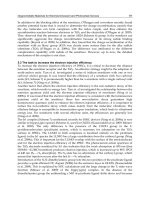
Generally, organic materials have strong ultraviolet (UV) and infrared (IR) absorption bands
attributed to electronic and vibrational transitions, respectively as shown in figure 5.
Therefore, UV or IR lasers have been typically used for organic material laser transfer by the
direct laser absorption in the same organic material or a separate light absorbing organic
material. However, organic compounds have high vapor pressures and can be easily
damaged by thermal decomposition or degradation induced from photodecomposition by
direct UV absorption or thermal decomposition by IR absorption. This is also the case even
using an additional light absorbing organic layer. To overcome this problem, a thin metal
film layer can be introduced as visible laser light absorber. However, this may cause organic
material thermal degradation because the metal film usually has high melting or ablation
threshold and exhibits inefficient energy coupling due to high reflectivity.
wavelength
Absorption
OLED material absorption peak (usually in UV
and IR)
Light to heat conversion layer absorption peak
-> wavelength choice can be optimized by selecting
different nanoparticle, size etc.
wavelength
Absorption
wavelength
Absorption
OLED material absorption peak (usually in UV
and IR)
Light to heat conversion layer absorption peak
-> wavelength choice can be optimized by selecting
different nanoparticle, size etc.
Fig. 5. Light to heat conversion layer engineering for OLED laser transfer
Ko et al. reported a nanomaterial enabled laser transfer (NELT) method to facilitate the
patterning and transfer of the heat-sensitive OLED material. This is characterized by the
introduction of an efficient light absorbing nanomaterial layer and the choice of laser
wavelength that although is strongly absorbed by the properly engineered nanomaterial, it
interacts only weakly with the organic material of interest, leading to effective evaporation
and transfer of the material with less damage potential. (Ko et al. 2008)
The illustration of the NELT process and the donor multilayer is shown in Figure 6(a). Either
a large area homogenized beam or a tightly focused Gaussian Nd:YAG pulsed laser beam
(wavelength = 532 nm, pulse width = 5 ns FWHM) were applied normal to the donor
substrate to induce the local heating of nanoparticle and the transfer of a target film onto a
receptor substrate. The homogenized Nd:YAG laser beam cross section was shaped to a 0.9
× 0.9 mm2 flat top beam profile of good spatial uniformity by a micro-lens laser beam
homogenizer while the tightly focused laser beam size had a 2~10 μm (FWHM) 1/e
2
diameter Gaussian profile. The applied laser fluence was around 0.05~0.15 J/cm
2
. The donor
was composed of three parts; transparent substrate (glass slide) / laser-to-heat conversion
layer (nanomaterials) / target material (OLED material). Self assembled monolayer (SAM)
protected silver nanoparticles (Ag NPs) (30~40 nm sized, Figure 6(a) insets) were used as
the laser-to-heat conversion nanomaterial layer by spin-coating on the glass substrate to
form a 100~200 nm layer. The SAM coating serves to stabilize the Ag NPs and prevent
Unconventional, Laser Based OLED Material Direct Patterning and Transfer Method
203
coalescence into a bulk film. (Korge et al. 1998) The optical property measurement by
spectroscopic ellipsometry (Figure 6(b)) shows the NP film has strong absorption around
530 nm facilitating highly efficient energy absorption to the NPs laser while the polymer
material exhibits little absorption. The target OLED material was tris-(8-
hydroxyquinoline)Al (Alq3) layer deposited by a resonant infrared pulsed laser deposition
(RIR-PLD) technique to form 200~300 nm layer on top of Ag NP film on a glass slide. The
donor substrate was then placed in intimate contact with the receptor substrate in ambient
air environment. The receptor substrate was a glass substrate with thin PDMS layer on top
as an adhesion promoter.
-10
-5
0
5
10
15
20
400 600 800 1000 1200
1
2
Dielectric constants
Wavelength [nm]
Glass
NPs
OLED
material
Donor
Receptor
Transferred pattern
NPs
Nd:YAG laser
(532nm, 5 ns)
Glass
NPs
OLED
material
Donor
Receptor
Transferred pattern
NPsNPs
Nd:YAG laser
(532nm, 5 ns)
(a)
(b)
-10
-5
0
5
10
15
20
400 600 800 1000 1200
1
2
Dielectric constants
Wavelength [nm]
Glass
NPs
OLED
material
Donor
Receptor
Transferred pattern
NPs
Nd:YAG laser
(532nm, 5 ns)
Glass
NPs
OLED
material
Donor
Receptor
Transferred pattern
NPsNPs
Nd:YAG laser
(532nm, 5 ns)
(a)
(b)
NPsNPs
Laser (selectively absorbed by NPs)Laser (selectively absorbed by NPs)
Heat transfer and NPs evaporationHeat transfer and NPs evaporation
Fig. 6. (a) Schematic illustration of the NELT process and the donor multilayer (Alq3/Ag
NPs/glass) structure. The inset pictures are schematics of SAM protected NPs and the SEM
picture of the spin coated Ag NPs. Inset scale corresponds 100nm. (b) Ellipsometric
measurement of the NPs film optical property. (Ko et al. 2008)
Figure 7(a-c) shows fluorescence pictures of (a) a donor substrate and (b,c) transferred
Alq3 patterns on a PDMS/glass substrate after homogenized Nd:YAG laser transfer. The
black squares in Figure 7(a) mark donor regions where single laser pulses (0.07 J/cm
2
)
transferred corresponding Alq3 patterns (0.9×0.9 mm
2
squares with 2 mm pitch) on a
receptor substrate (Figure 7(b)). Figure 7(d) shows the donor cross section SEM picture
near the laser beam edge and figure 7(e,f) show the corresponding magnified pictures.
The micrograph of individual transferred Alq3 pattern (Figure 7(c)) and the SEM picture
(Figure 7(g)) indicate that the transfer was very successful with well-defined edges and
strong fluorescence without any visible cracks on the Alq3 surface. If the Alq3 layer
becomes damaged, the layer will cease to fluoresce or the intensity will be greatly
reduced. The thickness of the transferred layer was about 200 ~ 300 nm corresponding to
the thickness of the Alq3 layer on the donor substrate structure as well as a small amount
of the nanoparticle matrix layer.
Organic Light Emitting Diode – Material, Process and Devices
204
200μm200μm
Transferred Alq
3
Donor
(a)
(b) (c)
(g)
100 μm
200 nm
(f)
500 nm200 nm
(e)
Alq
3
NPs
Glass
(i)
1 μm
(ii)
(iii)
(d)
Laser irradiation
200μm200μm
Transferred Alq
3
Donor
(a)
(b) (c)
(g)
100 μm
200 nm
(f)
500 nm200 nm
(e)
Alq
3
NPs
Glass
(f)
500 nm200 nm
(e)
Alq
3
NPs
Glass
(i)
1 μm
(ii)
(iii)
(d)
Laser irradiation
Fig. 7. Fluoresce pictures of (a) a donor substrate and (b) transferred Alq3 patterns
(0.9×0.9mm
2
squares with 2 mm pitch) on a PDMS/glass substrate under UV lamp
illumination. (c) Magnified fluoresce micrograph of individual transferred Alq3 pattern
under UV lamp illumination. (d) SEM cross sectional picture near laser edge along line (i) in
(a). Magnified SEM cross sectional pictures of original donor with Alq3/Ag NPs/glass
structure before laser transfer and of (f) donor after laser transfer at (ii) and (iii) in (d)
respectively. (g) SEM top view picture of transferred Alq3/Ag on PDMS/glass substrate.
Inset is the magnified SEM top view picture. (Ko et al. 2008)
Nanomaterials exhibit remarkable properties that may be substantially different from those
observed in the bulk counterparts due to the large surface-to-volume ratio, large surface
energy, and the confinement of molecules, atoms, and electrons within a small spatial
region. Note that the typical laser fluence (0.07-0.12 J/cm
2
) used for NELT based on Ag NPs
is considerably lower than the reported ablation threshold (Bäuerle et al. 2000) for metal
films (1–10 J/cm
2
) for nanosecond laser irradiation at visible wavelength.
Proper selection of nanoparticle size, size distribution, as well as the material type may
allow highly efficient laser energy coupling via tuning to an absorption peak. Noble metal
NPs such as Au and Ag exhibit strong absorption peaks in the visible wavelength region
that are typically not observed in the bulk materials due to surface plasmon oscillation
modes of conduction electrons in the nanoparticles (Figure 8). Additionally, enhanced
electric fields between nanoparticles may contribute to more efficient energy absorption
mechanisms. (Ko et al. 2006)
Unconventional, Laser Based OLED Material Direct Patterning and Transfer Method
205
1. Efficient and local energy deposition
->Strong absorption (Rayleigh scattering regime
+ surface plasmon)
2. Low ablation threshold
6
8
1
2
4
6
8
10
2
4
6
8
100
2
4
Absorption depth [m]
1.21.00.80.60.4
Wavelen
g
th
[
m
]
Effective medium absorption depth for 5nm gold particles
Rayleigh absorption depth for 5nm gold particles
Mie absorption depth for 5nm gold particles
6
8
1
2
4
6
8
10
2
4
6
8
100
2
4
Absorption depth [m]
1.21.00.80.60.4
Wavelen
g
th
[
m
]
Effective medium absorption depth for 5nm gold particles
Rayleigh absorption depth for 5nm gold particles
Mie absorption depth for 5nm gold particles
Thermodynamic property :
size dependent melting temperature
depression
& , 1976
5 10 15 20
T(°C)
1000
800
600
400
200
200nm
Bulk gold melting temp. = 1063°C
Buffat Borel
Diameter (nm)
200nm
& , 1976
5 10 15 20
T(°C)
1000
800
600
400
200
200nm
Bulk gold melting temp. = 1063°C
Buffat Borel
Diameter (nm)
200nm
5 10 15 20
T(°C)
1000
800
600
400
200
200nm
Bulk gold melting temp. = 1063°C
Buffat Borel
Diameter (nm)
200nm
Fig. 8. Optical property and melting temperature depression of metal nanoparticles.
For efficient energy absorption, the deposited energy may be more confined to the laser
focal zone due to the reduced thermal diffusion of nanoparticle thin films. This implies that
the relatively lower thermal conductivity of a nanoparticle thin film reduces the rate of
lateral energy dissipation, thereby facilitating the heating, evaporation and transfer
processes. The low thermal conductance of the alkanethiol SAM is due to the vibrational
mismatch between the nanoparticle solid core and the surface coating as reported by several
researchers. (Wilson et al. 2002, Wang et al. 2006)
The melting temperature depression may also enable ablation driven by the nanomaterial
melting and vaporization at much lower laser energies than for bulk materials. (Figure 8)
Upon reaching the SAM desorption temperature (typically at about 150~250ºC), the SAM
coating may be removed. At this stage, molten nanoparticles agglomerate to form larger
particles or are expelled by the pressure built up from the volatile species expansion
attributed to desorbed SAM, vaporized residual organic solvent and trapped gases.
Additionally, due to the presence of the SAM coating, the nanoparticles may be held
together by weak physical van der Waals force compared with the strong metal bonding in
thin metal film. (Altman et al. 2005) Therefore, the expulsion may be enhanced by the
relatively weak bonding between the nanoparticles.
Due to the combined aforementioned effects, NELT results in laser transfer at relatively
smaller laser energy with minimal thermal damage to the target OLED material. The Alq3
layer shows strong decrease in fluorescence if the temperature exceeds approximately
300ºC. Therefore, the Alq3 layer does not encounter higher temperatures during the laser
transfer process.
Figures 9 and 10 illustrate that this process can fabricate Alq3 patterns of arbitrary shape.
Figure 9 shows step and pixelized transfer of Alq3 patterns by irradiation of a large area
homogenized laser beam (of ~mm size) while figure 4 depicts Alq3 patterning by tightly
focused Gaussian laser beam (<10μm). Figure 9 displays photographs of the fluorescing
transferred Alq3 patterns on a PDMS/glass substrate under UV lamp illumination. The
green letters (a) “UCB”, (e) “LTL” and the star shapes correspond to regions where the laser
irradiation resulted in the transfer of the Alq3 material from the donor substrate to the
receptor substrate. The “UCB” and “LTL” letters were formed from combining the 0.9×0.9
Organic Light Emitting Diode – Material, Process and Devices
206
mm2 squares with single laser pulse (0.072 J/cm
2
). The lines of stars indicated at (a-i,ii) and
(e-i,iii) were patterned using a homemade aluminum mask on a glass slide (placed before
the objective lens for scaling down the projection of the mask at 1:10 reduction) using the
same pulse energy as for the above letters. Figures 9(b-d), (f-h) show the magnified
fluorescence micrograph of individual transferred Alq3 pattern of star shapes (b,f) and
letters (c,d,g,h). The bubbles appearing in Figure 9(a,e) are in the PDMS adhesion layer
and not a result of the Alq3 laser transfer process. In all cases, the fluorescence of the
transferred Alq3 is strong, indicating no damage during the transfer process.
Additionally, the edges of the transferred patterns are sharp and well defined, confirming
good spatial control of the transfer.
(i)
(a)
(b)
(c)
(d)
500 μm
(ii)
(iii)
(d)
(i)
(ii)
(iii)
(e)
(f)
(g)
(h)
500 μm
(i)
(a)
(b)
(c)
(d)
500 μm
(ii)
(iii)
(d)
(i)
(ii)
(iii)
(e)
(f)
(g)
(h)
500 μm
Fig. 9. Step and irradiation of large sized homogemized beam. Fluoresce pictures of
transferred Alq3 patterns on a PDMS/glass substrate under UV lamp illumination. (a) (i)
star shapes made by homemade mask and (ii~iii) “LTL” letters made by 0.9 × 0.9 mm2
squares. Magnified fluoresce micrograph of individual transferred Alq3 pattern of (b) star
shapes, (c~d) letters under UV lamp illumination. (e) (i) star shapes made by homemade
mask and (ii~iii) “UCB” letters made by 0.9 × 0.9 mm2 squares. Magnified fluoresce
micrograph of individual transferred Alq3 pattern of (f) star shapes, (g~h) letters under UV
lamp illumination. Small circles are the bubbles formed in PDMS layer and has nothing to
do with current process. (Ko et al. 2008)
Figure 10 shows fluorescence pictures of transferred Alq3 patterns on a PDMS/glass
substrate by raster scanning tightly focused Gaussian laser pulses. Alq3 micro dot arrays
were transferred by (a,b) 5X, (c) 20X, (d) 50X objective lens focusing. A range of sizes of Alq3
micro dot arrays ((a,b) 20~25 μm (5X), (c) 5 μm (20X), (d) 3 μm (50X)) could be transferred
via the objective lens focusing. Alq3 micro dot arrays were smaller than the original focused
laser beam size (5X: 10 μm, 20X: 3 μm, 50X: 2 μm). Instead of using single laser irradiation of
homogenized large area beam to transfer 1 mm2 square patterns as shown in Figure 7,
square patterns of similar size and quality could be achieved by raster scanning a laser beam
focused by a 5X objective lens along the arrow direction (Figure 10(d)).
Unconventional, Laser Based OLED Material Direct Patterning and Transfer Method
207
(e)
100 μm
100 μm
100 μm
100 μm
100 μm
(a)
(b)
(c)
(d)
(e)
100 μm
100 μm
100 μm
100 μm
100 μm
(a)
(b)
(c)
(d)
Fig. 10. Raster scanning of focused Gaussian beam. Fluoresce pictures of transferred Alq3
patterns on a PDMS/glass substrate under UV lamp illumination. Alq3 dot arrays
transferred by (a,b) 5X, (c) 20X, (d) 50X objective lens focusing. 1 mm
2
square by raster
scanning of focused laser with 5X objective lens. Arrow indicates laser spot scanning
direction. (Ko et al. 2008)
In summary, the nanomaterial enabled laser transfer (NELT) method was demonstrated to
directly pattern and transfer Alq3 through laser absorbing layer engineering. The combined
effects of melting temperature depression, lower conductive heat transfer loss, strong
absorption of the incident laser beam, and relatively weak bonding between nanoparticles
during laser irradiation result in the transfer of patterns with very sharp edges at relatively
lower laser energy than commonly used, thus inducing minimal damage to the target OLED
material with no evidence of cracks. This technique is not limited to the current specific
combination of the Ag NPs with alkanethiol SAM protective layer and the utilized laser
wavelength, but can be applied to a broad range of laser wavelengths with proper selection
of nanoparticle size and size distribution, as well as the material type. Additionally, NELT
may be particularly advantageous for the mass production of temperature sensitive devices.
2.5 Self Assembled Monolayer assisted Nanomaterial Enabled Laser Transfer [SAM-
NELT]
NELT process could demonstrate the OLED material pixel transfer. The NPs were used to
facilitate the OLED material transfer at low laser energy. Some part of NPs will transferred
from donor substrate on OLED material surface. The transferred NPs may be beneficial for
some points such that they can be used for metal electrode or may enhance the
luminescence by surface plasmon. However, for some application, there is a strong needs
for modified NELT process without using NPs. In this section, self assembled monolayer
assisted NELT (SAM-NELT) is introduced for variant of NELT process.
Organic Light Emitting Diode – Material, Process and Devices
208
Figure 11 illustrates the schematics of NELT process (Figure 11(a)) and the two types of
donor multilayer (figure 11(b)). Either a large area homogenized beam or a tightly focused
Gaussian Nd:YAG pulsed laser beam (wavelength = 532 nm, pulse width = 5 ns FWHM)
were applied normal to the donor substrate which was composed of three parts;
transparent substrate (borosilicate glass slide) / laser-to-heat conversion layer
(nanomaterials) / target material (OLED material). The applied laser induces the local
heating of laser-to-heat conversion layer and the transfer of the OLED material patterns
onto the flexible receptor substrate. In this experiment, two types of SAM (self assembled
monolayer, Alkanethiol) coated nanomaterials were used as the laser absorbing and
dynamic releasing layer: SAM coated Ag nanoparticle thin film (type I) or SAM layer
coated Au thin film (type II). SAM protected Ag nanoparticles (30~40 nm sized) were
spin-coated on the glass substrate to form a 100~200 nm thin film and SAM coated Au
thin film (100nm on 5nm Cr layer) was prepared by e-beam evaporation and subsequent
SAM coating. The homogenized Nd:YAG laser beam cross section was shaped to a 0.9 ×
0.9 mm
2
flat top beam profile of good spatial uniformity by a micro-lens laser beam
homogenizer while the tightly focused laser beam size had a 2~10 μm (FWHM) 1/e
2
diameter Gaussian profile. The applied laser fluence was around 0.05~0.15 J/cm
2
for type
I donor with SAM coated Ag nanoparticle thin film and 0.01~0.05 J/cm
2
for type II donor
with SAM coated Au thin film. The optical property measurement by spectroscopic
ellipsometry) indicates the nanoparticle thin film has strong absorption around 530 nm
facilitating highly efficient Nd:YAG laser absorption to the NPs laser while the polymer
material exhibits little absorption. The target OLED material were 1) green fluorescent
monomer: tris-(8-hydroxyquinoline)Al (Alq3) layer (200~300 nm) deposited by a resonant
infrared pulsed laser deposition (RIR-PLD) technique (Dubb et al, 2001) and 2) blue
fluorescent polymer: PFO layer (100~300nm) deposited by spincoating. RIR-PLD was
done by Free-Electron Laser (FEL) with the wavelength of 6.67 µm, which corresponds to
the resonance peak of Alq3 absorption in IR, 5µs pulse width, and fluence of 1.5 J/cm
2
at
30 Hz for 2-3 minutes. The donor substrate was then placed on top of the receptor
substrate with a small gap or intimate contact with the acceptor substrate in ambient air
environment. The receptor substrate was a thin PDMS layer.
Objective
Lens
Beam
Homogenizer
Nd:YAG
Laser (532nm)
Motorized stages
(a)
(b)
Glass
Functional
transfer
layer
OLED
material
Donor
Receptor
Transferred
pattern
Nd:YAG laser
(532nm, 5 ns)
S
R
S
R
S
R
S
R
S
R
Au
Alq3
SAM
Glass
Au
Alq3
NPs
Glass
Type I
Type II
Fig. 11. (a) Schematic diagram of experimental set up for a nanomaterial enabled laser
transfer with a homogenized Nd:YAG laser. (b) Magnified schematic illustration of the laser
transfer process and the two types of donor multilayer. (Ko et al. 2010)
Unconventional, Laser Based OLED Material Direct Patterning and Transfer Method
209
For certain applications, these nanoparticles transferred with the OLED material can be
regarded as the contaminants. This side-effect can be removed by using type II donor. The
micrographs of individual transferred Alq3 and PFO patterns from type II donor show
successful OLED material transfer without damaging or transferring of Au thin film.
Transferred OLED material pattern can be controlled by laser scanning or laser beam
shaping. Alternatively, selective transfer can be induced by pre-patterning of laser
absorbing layer. Figure 12 shows the schematics and the fluorescent pictures of transferred
Alq3 pattern on the PDMS substrate (Fig. 12(b)) and the donor substrate (Fig. 12(c)). Laser
was scanned for large area with constant laser energy, and the transfer happened only for
the area with pre-patterned type II donor (SAM coated Au thin film).
(a)
S
R
S
R
S
R
S
R
S
R
Au
Alq3
SAM
Glass
Au
Type II
Laser scanning
100 μm
(b) (c)
Fig. 12. (a) Schematic diagram of selective NELT process for a pre-patterned type II donor
substrate. (b) Fluorescent images of (b) transferred Alq3 patterns on a PDMS film and (c)
donor substrate after NELT process. (Ko et al. 2010)
3. Conclusion
Organic light emitting diode (OLED) displays have a number of desirable features such as
high contrast and brightness, wide color range, thin structure and light weight, among
others and OLED displays have several manufacturing requirements such as large area
scalability and an increasing push towards smaller feature sizes, tighter feature shape
control, high yield and low cost. However, traditional lithography and thermal evaporation
deposition techniques have significant disadvantages, including the need for masks that are
typically difficult to make to the required specifications at a reasonable price. Vacuum-
processable OLEDs have been patterned mostly by deposition through a shadow mask or
fine-metal mask (FMM). Deposition can be accomplished either as a conventional physical
evaporation or organic vapour phase deposition (OVPD), but FMM-related patterning
issues are largely independent of the deposition technique. Remaining FMM patterning
issues include difficulty of fabricating high resolution masks for large-area displays, mask
lifetime and cleaning, particle contamination, and thermal expansion effects. Therefore,
there is a strong need to develop a novel process instead of complex modification of
Organic Light Emitting Diode – Material, Process and Devices
210
conventional vacuum deposition and photolithography based processes. OLED display
manufacturing employs direct write techniques for patterning the various materials.
Examples of OLED material direct write technologies include ink jet printing, screen
printing and laser induced forward transfer (LIFT). Solution processible direct write
technologies such as inkjet printing and screen printing are subject to a number of
limitations such as the need for solvent removal and contamination into the deposited
material. Additionally, the minimum feature size is heavily influenced by the properties of
the fluid used to deliver the material of interest and multilayer structure fabrication is
difficult. In this chapter, unconventional OLED material direct patterning and transfer
methods especially laser based forward transfer and patterning approaches were presented
as promising potential alternative to conventional OLED fabrication methods.
4. Acknowledgment
The authors would like to thank Dr. H.K. Park of AppliFlex LLC, (CA, USA) for his advices
and supports. The authors also would like gratefully acknowledge the financial supports to
KAIST by the Industrial Strategic Technology Development Program from the Korea
Ministry of Knowledge Economy (Grant No. 10032145), the National Research Foundation
of Korea (Grant No. 2010-0003973), the cooperative R&D Program from the Korea Research
Council Industrial Science and Technology (Grant No. B551179-10-01-00), and the support to
the University of California, Berkeley by the NSF STTR (Grant No. 0930594) through
Appliflex LLC, CA, USA.
5. References
Arnold, C.; Serra, P. & Piqué, A. (2007) Laser direct-write techniques for printing of complex
materials. MRS Bull. Vol.32, No.1, (Jan 2007) pp.23-31, ISSN 0883-7694.
Altman, I.S.; Agranovski, I.E. & Choi, M. (2005) Mechanism of nanoparticle agglomeration
during the combustion synthesis. Appl. Phys. Lett. Vol.87, No.5, (Aug 2005) 053104
ISSN 0003-6951.
Bao, Z.; Feng, Y.; Dodavalapur, A.; Raju, V.R. & Lovinger, A.J. (1997) High-Performance
Plastic Transistors Fabricated by Printing Techniques. Chem. Mater. Vol.9, No.6,
(Jun 1997) pp.1299-301, ISSN 0897-4756.
Bäuerle, D., Laser Processing and Chemistry (Springer, New York, 2000).
Blanchet, G.B.; Loo, Y L.; Rogers, J.A.; Gao F. & Fincher, C.R. (2003a) Large area, high
resolution, dry printing of conducting polymers for organic electronics. Applied
Physics Letters Vol.82, No.3, (November 2002), pp. 463-465, ISSN 0003-6951.
Blanchet, G.B.; Loo, Y L.; Rogers, J.A.; Gao F. & Fincher, C.R. (2003b) Large Area Printing of
Organic Transistors via a High Throughput Dry Process. Mat. Res. Soc. Symp. Proc.
pp. 283-287, Vol. 736, Boston, MA, USA, Dec 2-32002.
Boroson, M.; Tutt, L.; Nguyen, K.; Preuss, D.; Culver, M. & Phelan, G. (2005) Non-Contact
OLED Color Patterning by Radiation- Induced Sublimation Transfer (RIST). SID
Symposium Digest, Vol.36, No.1, pp.972-975 (May 2005), ISSN 0003-966X.
Bubb, D.M.; Horwitz, J.S.; Callahan, J.H.; McGill, R.A.; Houser, E.J. & Chrisey, D.B.;
Papantonakis, M.R.; Haglund, Jr., R.F.; Galicia M.C. & Vertes, A. (2001) Resonant
Unconventional, Laser Based OLED Material Direct Patterning and Transfer Method
211
infrared pulsed-laser deposition of polymer films using a free-electron laser. J. Vac.
Sci. Technol. A Vol.19, No.5, (Sep 2001) 2698, ISSN 0734-2101.
Chrisey, D.; Piqué, A.; McGill, R.; Horwitz, J.; Ringeisen, B.; Bubb, D. & Wu, P. (2003) Laser
deposition of polymer and biomaterial films. Chem. Rev. Vol.103, No.2, (Feb 2003)
pp.553-576, ISSN 0009-2665.
Chrisey, D. B.; Piqué, A.; Modi, R.; Wu, H.D.; Aueyung, R.C.Y.; Young, H.D. (2000) Direct
writing of conformal mesoscopic electronic devices by MAPLE DW. Appl. Surf. Sci.
Vol.168, No.1-4, (Dec 2000), pp.345-352, ISSN 0169-4332.
Chung, J.; Ko, S.; Bieri, N.R.; Grigoropoulos, C.P.; Poulikakos, D., (2004a) Conductor
microstructures by laser curing of printed gold nanoparticle ink. Appl. Phys. Lett.,
Vol.84, No.5, (Feb 2004), pp. 801-803, ISSN 0003-6951.
Chung, J.; Ko, S.; Grigoropoulos, C.P.; Bieri, N.R.; Dockendorf, C.; Poulikakos, D. (2005)
Damage-free low temperature pulsed laser printing of gold nanoinks on polymers,
ASME Journal of Heat Transfer, Vol.127, No.7, (Jul 2005), pp. 724-732, ISSN 0022-
1481.
Chung, J.; Bieri, N.R.; Ko, S.; Grigoropoulos, C.P.; Poulikakos, D. (2004b) In-tandem
deposition and sintering of printed gold nanoparticle inks induced by continuous
Gaussian laser irradiation, Applied physics A-Materials science and processing, Vol.79,
No.4-6, (Sep 2004), pp. 1259-1261, ISSN 0947-8396.
Fardel, R.; Nagel, M.; Nüesch, F.; Lippert, T. & Wokaun. A. (2007) Fabrication of organic
light-emitting diode pixels by laser-assisted forward transfer. Appl. Phys. Lett.
Vol.91, No.6, (Aug 2007) 061103 ISSN 0003-6951.
Funamoto, T.; Matsueda, Y.; Yokoyama, O.; Tsuda, A.; Takeshita, H.; Miyashita, S. (2002) A
130-ppi, Full-Color Polymer OLED Display Fabricated Using an Ink-jet Process,
SID Symposium Digest, Vol.33, No.1, pp.899-901, (May 2002) ISSN 0003-966X.
Fleuster, M.; Klein, M.; Roosmalen, P.V.; Wit, A.D.; Schwab, H. (2004) Mass Manufacturing
of Full Color Passive-Matrix and Active-Matrix PLED Displays. SID Symposium
Digest, Vol.35, No.1, pp. 1276- 1279, (May 2004) ISSN 0003-966X.
Gohda, T.; Kobayashi, Y.; Okano, K.; Inoue, S.; Okamoto, K.; Hashimoto, S.; Yamamoto, E.;
Morita, H.; Mitsui, S. & Koden, M. (2006) A 3.6-in. 202-ppi Full-Color AMPLED
Display Fabricated by Ink-Jet Method, SID Symposium Digest, Vol.37, No.1, pp.1767-
1770, (May 2006) ISSN 0003-966X.
Ganier, F.; Hajlaoui, R.; Yasser, A. & Srivastava, P. (1994) All-polymer field effect transistor
realized by printing technique. Science Vol.265, No.5179, (Sept 1994) pp.1684-86,
ISSN 0036-8075.
Hirano, T.; Matsuo, K.; Kohinata, K.; Hanawa, K.; Matsumi, T.; Matsuda, E.; Matsuura, R.;
Ishibashi, T.; Yoshida, A. & Sasaoka, T. (2007) Novel laser transfer technology for
manufacturing large-sized OLED displays. SID Symposium Digest, Vol.38, No.1,
pp.1592-1592, (May 2007) ISSN 0003-966X.
Kashiwabara, M.; Hanawa, K.; Asaki, R.; Kobori, I.; Matsuura, R.; Yamada. H.; Yamamoto,
T.; Ozawa, A.; Sato, Y.; Terada, S.; Yamada, J.; Sasaoka, T.; Tamura, S. & Urabe, T.
(2004) Advanced AM-OLED Display Based on White Emitter with Microcavity
Structure. SID Symposium Digest, Vol.35, No.1, pp.1017-1019, (May 2004) ISSN 0003-
966X.
Organic Light Emitting Diode – Material, Process and Devices
212
Ko, S.H.; Pan, H.; Grigoropoulos, C.P.; Luscombe, C.K.; Fréchet, J.M.J.; Poulikakos, D.
(2007b) Air stable high resolution organic transistors by selective laser sintering of
ink-jet printed metal nanoparticles. Appl. Phys. Lett., Vol.90, No.14, (Apr 2007)
141103 ISSN 0003-6951.
Ko, S.H.; Pan, H.; Grigoropoulos, C.P.; Luscombe, C.K.; Fréchet, J.M.J.; Poulikakos, D.
(2007c) All-inkjet-printed flexible electronics fabrication on a polymer substrate by
low-temperature high-resolution selective laser sintering of metal nanoparticles.
Nanotechnology, Vol.18, No.34, (Aug 2007) 345202 ISSN 0957-4484.
Ko, S.H.; Pan, H.; Grigoropoulos, C.P.; Luscombe, C.K.; Fréchet, J.M.J. & Poulikakos, D.
(2007) All inkjet printed flexible electronics fabrication on a polymer substrate by
low temperature high resolution selective laser sintering of metal nanoparticles.
Nanotechnology Vol.18, No.34, (August 2007) 345202, ISSN 0957-4484.
Ko, S.H.; Pan, H.; Ryu, S.G.; Misra, N.; Grigoropoulos, C.P. & Park, H.K. (2008)
Nanomaterial Enabled Laser Transfer for Organic Light Emitting Material Direct
Writing, Applied Physics Letters Vol.93, No.15, (Oct 2008) 151110, ISSN 0003-6951.
Ko, S.; Choi, Y.; Hwang, D.J.; Grigoropoulos, C. P.; Chung J. & Poulikakos, D. (2006)
Nanosecond laser ablation of gold nanoparticle films. Appl. Phys. Lett. Vol.89,
No.14, (Oct 2006) 141126, ISSN 0003-6951.
Ko, S.H.; Chung, J.; Pan, H.; Grigoropoulos, C.P.; Poulikakos, D. (2007a) Fabrication of
multilayer passive and active electric components on polymer using inkjet printing
and low temperature laser processing. Sensors and Actuators A: Physical, Vol.134,
No.1, (Feb 2007) pp.161-168, ISSN 0924-4247. 17.
Ko, S.H.; Pan, H.; Lee, D.; Grigoropoulos, C.P.; Park, H.K. (2010) Nanoparticle Selective
Laser Processing for a Flexible Display Fabrication. Jpn. J. Appl. Phys., Vol.49, No.5,
(May 2010) 05EC03 ISSN 1347-4065.
Korgel, B.A.; Fitzmaurice, D. (1998) Self-assembly of silver nanocrystals into two-
dimensional nanowire arrays. Adv. Maters. Vol.10, No.9, (Jun 1998) pp.661-665 ISSN
0935-9648.
Kobayashi, M.; Hanari, J.; Shibusawa, M.; Sunohara, K.; Ibaraki, N. (2002) A 17-in Full-Color
OLED Display by Using Polymer Ink-Jet Technology. Proc Int Disp Workshops, pp.
231-234, (2002).
Kyrkis, K.; Andreadaki, A.; Papazoglou, D. & Zergioti, I. (2006) In: Recent Advances in Laser
Processing of Materials, J. Perrière, E. Millon, and E. Fogarassy (Ed.), 213–241,
Elsevier, ISBN 978-0080447278.
Kang, C.H.; Kim, T.S. (2003) United States Patent Appl., US 2003/0221613 A1
Lamansky, S.; Hoffend Jr., T.R.; Le, H.; Jones, V.; Wolk, M.B.; Tolbert, W.A. (2005) Laser
Induced Thermal Imaging of Vacuum-Coated OLED Materials, In: Organic Light-
Emitting Materials and Devices IX, Z.H. Kafafi, P.A. Lane (Ed.), Vol.5937, 593702,
SPIE, IBSN 0-8194-5942-9.
Lee, S.; Chin, B.; Kim, Kang, M.T.; Song, M.; Lee, J.; Kim, H.; Chung, H.; Wolk, M.; Bellmann,
E.; Baetzold, J.; Lamansky, S.; Savvateev, V.; Hoffend, T.; Staral, J.; Roberts, R.; Li, Y.
(2004) A Novel Patterning Method for Full-Color Organic Light- Emitting Devices:
Laser Induced Thermal Imaging (LITI). SID Symposium Digest, Vol.35, No.1, (May
2004) pp.1008-1011, ISSN 0003-966X.
Unconventional, Laser Based OLED Material Direct Patterning and Transfer Method
213
Lee, S.T.; Lee, J.Y.; Kim, M.H.; Suh, M.C.; Kang, T.M.; Choi, Y.J.; Park, J.Y. (2002) A New
Patterning Method for Full-Color Polymer Light-Emitting Devices: Laser Induced
Thermal Imaging (LITI). SID Symposium Digest, Vol.33, No.1, (May 2002) pp.784-
787, ISSN 0003-966X.
Lee, D.; Chung, J.; Rhee, J.S.; Wang, J.P.; Hong, S.M.; Choi, B.R.; Cha, S.W.; Kim, N.D.;
Chung, K.; Gregory, H.; Lyon, P.; Creighton, C.; Carter, J.; Hatcher, M. (2005) Ink Jet
Printed Full Color Polymer LED Displays. SID Symposium Digest, Vol.36, No.1,
(May 2005) pp. 527-529, ISSN 0003-966X.
Lee, D H.; Choi, J.S.; Chae, H.; Chung C H. & Cho, S.M. (2009) Screen-printed white OLED
based on polystyrene as a host polymer, Current Applied Physics, Vol.9, No.1, (Jan
2009), pp.161-164, ISSN 1567-1739.
Modi, R.; Wu, H. D.; Auyeung, R. C. Y.; Gilmore, C. M.; Chrisey, D.B.J. (2001) Direct writing
of polymer thick film resistors using a novel laser transfer technique. J. Mater. Res.
(2001) Vol.16, No.11, (Nov 2001), pp.3214-3222, ISSN 0884-2914.
Piqué, A.; Chrisey, D.B.; Auyeung, R.C.Y.; Fitz-Gerald, J.; Wu, H.D.; McGill, R.A.; Lakeou,
S.; Wu, P.K.; Nguyen, V.; Duignan, M. (1999) A novel laser transfer process for
direct writing of electronic and sensor materials. Appl. Phys. A, Vol.69, No.7, (1999)
S279, ISSN 0947-8396.
Redinger, D.; Molesa, S.; Yin, S.; Farschi, R.; Subramanian, V. (2004) An Ink-Jet-Deposited
passive component process for RFID, IEEE transactions on electron devices, Vol.51,
No.12, (Dec 2004), pp. 1978-1983, ISSN 0018-9383.
Saafir, A.K.; Chung, J.; Joo, I.; Huh, J.; Rhee, J.; Park, S.; Choi, B.; Ko, C.; Koh, B.; Jung, J.;
Choi, J.; Kim, N.; Cung, K.; Srdanov, G.; MacPherson, C.; Truong, N.; Stevenson,
M.; Johnson, A.; Chen, P.; Cardellino, T.; Pflanzer, R.; Yu, G.; Goenaga, A.; O’Regan,
M.; Keys, D. (2005) A 14.1” WXGA Solution Processed OLED Display with a-Si
TFT. SID Symposium Digest, Vol.36, No.1, (May 2005) pp. 968-971, ISSN 0003-966X.
Shirasaki, T.; Ozaki, T.; Sato, K.; Takei, M.; Toyama, T.; Shimoda, S. & Tano, T. (2004) Full-
color Polymer AM-OLED using Ink-jet and a-Si TFT Technologies. SID Symposium
Digest, Vol.35, No.1, (May 2004) pp. 1516- 1519, ISSN 0003-966X.
Suh, M.C.; Chin, B.D.; Kim, M.; Kang, T.M. & Lee. S.T. (2003) Enhanced luminance of blue
light-emitting polymers by blending with hole-transporting materials, Adv. Maters.,
Vol.15, No. 15, (August 2003), 1254, ISSN 0935-9648.
Shinar, J.; Shinar, R.; Zhou, Z. (2007) Combinatorial fabrication and screening of organic
light-emitting device. Applied Surface Science, Vol.254, No.3, (Nov 2007), pp.749-756,
ISSN 0169-4332.
Wang, R.Y.; Segalman, R.A. & Majumdar, A. (2006) Room temperature thermal conductance
of alkanedithiol self-assembled monolayers. Appl. Phys. Lett. Vol.89, No.17, (Oct
2006) 173113 ISSN 0003-6951.
Wolk, M.B.; Baetzold, J.; Bellmann, E.; Hoffend Jr, T.R.; Lamansky, S.; Li, Y.; Roberts, R.R.;
Savvateev, V.; Staral, J.S.; Tolbert, W.A. (2004) Laser Thermal Patterning of OLED
Materials, In: Organic Light-Emitting Materials and Devices VIII, Z.H. Kafafi, P.A.
Lane (Ed.), Vol.5519, pp. 12-23, IBSN 0-8194-5942-9.
Willis, D.A. & Grosu, V. (2005) Microdroplet deposition by laser-induced forward transfer.
Appl. Phys. Lett. Vol.86, No.24, (Jun 2005) 244103, ISSN 0003-6951.
Organic Light Emitting Diode – Material, Process and Devices
214
Wilson, O.M.; Hu, X.Y.; Cahill, D.G.; Barun, P.V. (2002) Colloidal metal particles as probes of
nanoscale thermal transport in fluids. Physical Review B Vol.66, No.22, (Dec 2002),
224301 ISSN 1098-0121.
Zschieschang, U.; Klauk, H.; Halik, M.; Schmid G. & C. Dehm (2003). Flexible organic
circuits with printed gate electrodes. Adv. Mater. Vol.15, No.14, (July 2003), pp. 147,
ISSN 0935-9648.
8
Interlayer Processing for Active Matrix Organic
Light Emitting Diode (OLED) Displays
Peter Vicca
1,4
, Soeren Steudel
1,4
, Steve Smout
1,4
, Kris Myny
1,4
,
Jan Genoe
1,3,4
, Gerwin G.H. Gelinck
1,4
and Paul Heremans
1,2,4
1
IMEC
2
Katholieke Universiteit Leuven
3
Katholieke Hogeschool Limburg
4
HOLST Centre
1,2,3
Belgium
4
The Netherlands
1. Introduction
At the moment, the display market is dominated by liquid crystal displays with amorphous
silicon (a-Si) thin film transistor (TFT) backplanes processed on glass. Within the last two
years, active matrix OLED (AMOLED) displays have rapidly expanded their market share
and are poised to break out of their niche application status. The brightness of OLEDs is
current controlled and therefore the driving engine behind every pixel is in its most simple
implementation comprising 2 transistors and 1 capacitor (2T1C) as in Figure 1. The required
current drive for the necessary brightness (> 500 cd/m
2
for cell phone display at > 72 dpi) is
however quite challenging for standard a-Si TFTs due to their relatively low mobility (~1
cm
2
/Vs).
The simplest implementation of a pixel engine for AMOLED current steering is depicted in
Figure 1. As a result, each pixel in the display contains 2 transistors and 1 capacitor. Since
OLEDs requires current driving, transistor 2 (T2) is used as a current source, whereby the
gate-source voltage determines the current level through the OLED. This gate-source
voltage is stored on capacitor C and can be modified by selecting transistor 1 (T1) via the
row select line. The voltage on the dataline is then transferred to the capacitor.
It is envisioned that the next generation of displays for handheld device will be flexible or
even rollable AMOLED displays realized on foils.
The substrate material for backplanes is typically glass, but could be replaced by a flexible
substrate, provided that low temperature materials are employed to create the backplane. A
working process for OTFTs in a backplane has been shown by Gelinck et al. Truly rollable
displays using organic TFTs have been shown recently either using e-ink by Huitema et al
(PolymerVision) or using OLEDs by Kawashima et al, Katsuhara et al and by Yagi et al, with
the organic TFTs possessing a similar performance to those of a-Si. In order to achieve a
sufficient light output, the preferred process flow implements top emitting OLEDs on top of
the driving engine resulting in an aspect ratio >70%. The choice of the flexible substrate
therefore will determine the process flow in a substantial way.