Organic Light Emitting Diode Material Process and Devices Part 12 pptx
Bạn đang xem bản rút gọn của tài liệu. Xem và tải ngay bản đầy đủ của tài liệu tại đây (735.49 KB, 25 trang )
Organic Light Emitting Diode – Material, Process and Devices
266
FOLED(10) were thought to have a lower electric and brightness properties than FOLED(0).
Although, the sheet resistance of 16 mm bent ITO is 230 /□, this value is sufficiently small
for using electrode in OLEDs.(Gu et al., 1996)
Fig. 31. Changes of the sheet resistance after the bending test of ITO films.
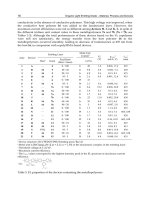
Fig. 32 showed the SEM images of the ITO surface as a function of the variation radius of
curvature. The crack phenomenon of bent ITO was appeared from the lowered radius of
bending test ≤ 16 mm. The ITO for the bending test at 13 mm and 10 mm radius showed the
rough surface and a large amount of crack from the whole area. In our case, the bent ITO at
16 mm, 13 mm, and 10 mm have the hasty reductive properties, such as sheet resistance and
surface morphology.
In this result, the reasons for reduced properties of bent FOLEDs are follows. Firstly, the
bent FOLEDs have lowered device characteristics, such as increased driving voltage and
decreased luminance property, because of the increase resistance of bent ITO by a bending
test in radius of below 16 mm.(Chen et al., 2002) Secondly, many attempts have been
focused on interface property between an organic and electrode layer. The OLEDs using the
ITO anode with smooth surface have shown superior device properties, as lower turn-on
voltage and higher luminescent efficiency, because these devices are improved contact
property. In this study, the bent FOLEDs have shown inferior device performance because
rough surface of the bent ITO was decreased contact property in the interface between the
TPD organic layer and ITO electrode.(Kwon et al., 2002) In conclusions, we fabricated
FOLEDs with an ITO anode, a TPD hole transport layer, an Alq
3
emitting layer, and an Al
cathode deposited on the PET substrate and studied FOLEDs characteristics after bending
test at various radiuses of 10 mm, 13 mm, 16 mm, and 19 mm. The performance of FOLEDs
with lowered radius ( 16 mm) was decreased the device properties, and increased the sheet
resistance of bent ITO. These devices showed the crack phenomena and rough surface in the
ITO and Al inorganic layers. In our experiment, the optimum radius of bending test was 19
mm. When FOLEDs was bent at 19 mm radius, inorganic layer, ITO and Al, cannot show the
crack phenomena. The electrical property and brightness efficiency of FOLED(19) were
similar with the control device. In this result was suggested that the performance of the bent
FOLEDs was affected significantly by the crack phenomenon of an inorganic layer and
increased sheet resistance of bent ITO.
Transparent Conductive Oxide (TCO) Films for Organic Light Emissive Devices (OLEDs)
267
Fig. 32. SEM images of the ITO surfaces (a) without bending and with bending as a function
of the variation radius of curvatures in (b) 16 mm, (c) 13 mm, and (c) 10 mm.
3. Conclusion
In fabricating OLED devices, ITO film among the TCO films is widely used as an anode
layer, because of its high transparency in the visible light range, low conductivity, and high
work function, etc. However, indium in ITO has a tendency to diffuse into the emissive
polymer layer under device operation, which may in turn influence the quantum efficiency
and lifetimes of OLEDs. In addition, it is known that the performance of ITO-based polymer
LEDs is highly dependent on the chemical condition of the ITO electrode, which is affected,
at least in part, by the particular method used to clean the ITO prior to device fabrication.
Therefore, various TCOs, such as ZnO based TCO or conducting polymer, nanometal, and
carbon nanotube, etc. have been investigated and can be applied in OLEDs and/or other
optoelectronic devices. For example, ZnO has the advantages, such as the absence of
toxicity, low cost, and good thermal stability. ZnO films with a hexagonal wurtzite structure
have a wide optical energy band gap (around 3.3 eV). However, the electrical properties of
undoped ZnO films are subjected to stoichiometric deviations resulting from oxygen
vacancies and interstitial zinc atoms. In order to improve this deficiency, many workers
have researched how the electrical properties of future TCO films are influenced by doping
or new material development.
4. Acknowledgment
This research was financially supported by the Second Stage of Brain Korea 21 Project and
the Ministry of Knowledge Economy(MKE), Korea Institute for Advancement of
Technology(KIAT) and Dae-Gyeong Leading Industry Office through the Leading Industry
Development for Economic Region.
5. Reference
Agura, H.; Suzuki, H.; Matsushita, T.; Aoki, T. & Okuda, M. (2003). Low Resistivity
Transparent Conducting Al-doped ZnO Films Prepared by Pulsed Laser
Organic Light Emitting Diode – Material, Process and Devices
268
Deposition. Thin Solid Films, Vol.445, No.2, (December 2003), pp. 263-267, ISSN
0040-6090
Banerjee, A.N. & Chattopadhyay, K.K. (2005). Recent Developments in The Emerging Field
of Crystalline p-Type Transparent Conducting Oxide Thin Films. Progress in Crystal
Growth and Characterization of Materials, Vol.50, No.3, (September 2005), pp. 55-105,
ISSN 0960-8974
Carter, S. A.; Angelopoulos, M.; Karg, S.; Brock, P. J. & Scott, J. C. (1997). Polymeric Anodes
for Improved Polymer Light-Emitting Diode Performance, Applied Physics Letters,
Vol.70, No.1, (April 1997), pp. 2067-2069, ISSN 0003-6951
Chan, I. M. & Hong, F. C. (2004). Improved Performance of The Single-Layer and Double-
Layer Organic Light Emitting Diodes by Nickel Oxide Coated Indium Tin Oxide
Anode. Thin Solid Films, Vol.450, No.2, (October 17 2003), pp. 304-311, ISSN 0040-
6090
Chen, M.; Pei, Z.; C, Sun.; L.S, Wen. & X, Wang. (2000). Surface Characterization of
Transparent Conductive Oxide Al-Doped ZnO Flms. Journal of Crystal Growth,
Vol.220, No.3, (February 2000), pp. 254-262, ISSN 0022-0248
Chen, T. H.; Liou, Y.; Wu, T. J. & Chen, J. Y. (2004). Enhancement of Organic Light-Emitting
Device Performances with Hf-Doped Indium Tin Oxide Anodes. Applied Physics
Letters, Vol.85, No.11, (April 2004), pp. 2092-2094, ISSN 1077-3118
Chen, Z.; Cotterell, Brian. & Wang, Wei. (2002). The Fracture of Brittle Thin Films on
Compliant Substrate in Flexible Displays. Engineering Fracture Mechanics, Vol.69,
No.5, (February 2002), pp.597-603, ISSN 0013-7944
Cho, M H.; Chang, H. S.; Cho, Y. J.; Moon, D. W.; Min, K H.; Sinclair, R.; Kang, S. K.; Ko,
D H.; Lee, J. H.; Gu, J. H. & Lee, N. I. (2004). Change in Chemical State and
Thermal Stability of HfO
2
by The Incorporation of Al
2
O
3
. Applied Physics Letters,
Vol.84, No.4, (May 2003), pp. 571-573, ISSN 1077-3118
Choi, B.G.; Kim, I. H.; Kim, D.H.; Lee, K.S.; Lee. T.S.; Cheong, B.; Baik, Y J. & Kim, W.M.
(2005) Electrical, Optical and Structural Properties of Transparent and Conducting
ZnO Thin Films Doped with Al and F by Rf Magnetron Sputter. Journal of The
European Ceramic Society, Vol.25, No.12, (March 2005), pp. 2161-2165, ISSN 0955-
2219
Choi, K.; Kim, J.; Lee, Y. & Kim, H. (1999). ITO/Ag/ITO Multilayer Films for The
Application of A Very Low Resistance Transparent Electrode. Thin Solid Films,
Vol.341, No.1-2, (March 1999), pp. 152-155, ISSN 0040-6090
Chowdhury, F U Z. & Bhuiyan, A.H. (2000). An Investigation of The Optical Properties of
Plasma-Polymerized Diphenyl Thin Films. Thin Solid Films, Vol.360, No.1-2,
(February 2000), pp. 69-74, ISSN 0040-6090
Chung, J L.; Chen, J C. & Tseng, C J. (2008). Preparation of TiO
2
-Doped ZnO Films by
Radio Frequency Magnetron Sputtering in Ambient Hydrogen-Argon Gas. Applied
Surface Science, Vol.255, No.5, (July 2008), pp. 2494-2499, ISSN 0169-4332
Custaffson, G.; Treacy, G. M.; Klavertter, Y. C.; Colaneri, N. & Heeger, A. J. (2003). The
“Plastic” Led: A Flexible Light-Emitting Device Using A Polyaniline Transparent
Electrode. Synthetic Metals, Vol.57, No.1, (February 2000), pp. 4123-4127, ISSN 0379-
6779
David, O.; Scanlon, Aron, W. & Graeme, W. W. (2009). Understanding the p-Type
Conduction Properties of the Transparent Conducting Oxide CuBO
2
: A Density
Transparent Conductive Oxide (TCO) Films for Organic Light Emissive Devices (OLEDs)
269
Functional Theory Analysis. Chemistry of Materials, Vol.21, No.19, (July 2009), pp.
4568–4576, ISSN 0897-4756
Deng, Z.B.; Ding, X.M. & Lee, S.T. (1999). Enhanced Brightness and Efficiency in Organic
Electroluminescent Devices using SiO
2
Buffer Layers. Applied Physics Letters, Vol.74,
No.15, (December 1998), pp. 2227-2229, ISSN 0003-6951
Dingle, R.; Störmer, H L.; Gossard, A.C. & Wiegmann, W. (1978). Electron Mobilities in
Modulation-Doped Semiconductor Heterojunction Superlattices. Applied Physics
Letters, Vol.33, No.7, (July 1978), pp.665-667, ISSN 0003-6951
Ghosh, C. K.; Popuri, S. R.; Mahesh, T. U. & Chattopadhyay, K. K. (2006). Preparation of
Nanocrystalline CuAlO
2
through Sol-Gel Route. Journal of Sol-Gel Science and
Technology, Vol.52, No.1 (March 2009), pp. 75-81, ISBN 0928-0707
Gu, G.; Bulović, V.; Burrows, P. E. & Forrest, S. R. (1996). Transparent Organic Light
Emitting Devices. Applied Physics Letters, Vol.68, (March 1996), pp. 2606-2608, ISSN
0003-6951
Guan, H S.; Gheng, C H.; Li, W C.; Geng, D F.; Fan, Z Q.; Chang, Y. C.; Zhao, W.; Guo,
Z Q. & Du. G T. (2009). Influence of Transparent Anode on Luminescent
Performance of Near-Infrared Organic Light-Emitting Diodes. Chemical Research in
Chinese Universities, Vol.25, No.6, (November 2009), pp. 786-789, ISSN 1005-9040
Guillen, G. & Herrero, J. (2009). Transparent Conductive ITO/Ag/ITO Multilayer
Electrodes Deposited by Sputtering at Room Temperature, Optics Communications,
Vol.282, No.4, (November 2008), pp. 574-578, ISSN 0030-4018
Gu, G.; Burrows, P. E.; Forrest, S. R. & Thompson, M. E. (1997). Vacuum-Deposited,
Nonpolymeric Flexible Organic Light-Emitting Devices. Optics Letters, Vol.22, No.3,
(1997), pp. 172-174, ISSN 0146-9592
Guo, Z.G.; Zhou, F.; Hao, J.C. & Liu, W.M. (2005). Stable Biomimetic Super-Hydrophobic
Engineering Materials. Journal of the American Chemical Society, Vol.127, No.45, (July
2005), pp. 15670-15671, ISSN 0002-7863
Han, J.; Mantas, P.Q. & Senos, A.M.R. (2001). Effect of Al and Mn Doping on the Electrical
Conductivity of ZnO. Journal of European Ceramic Society, Vol.21, No.10-11, (2001),
pp. 1883~1886, ISSN 0955-2219
He, T. & Kanicki, J. (2000). High-Efficiency Organic Polymer Light-Emitting Heterostructure
Devices on Flexible Plastic Substrates. Applied Physics Letters, Vol.76, No.6, pp. 661-
663, ISSN 0003-6951
Hirata, G.A.; McKittrick, J.; Cheeks, T.; Siqueiros, J.M.; Diaz, J.A.; Contreras, O. & Lpez, O.A.
(1996). Synthesis and Optoelectronic Characterization of Gallium Doped Zinc
Oxide Transparent Electrodes. Thin Solid Films, Vol.288, No.1-2, (November 1996),
pp. 29-31, ISSN 0040-6090
Honda, S.; Tsujimoto, A.; Watamori, M. & Oura, K. (1995). Oxygen Content of Indium Tin
Oxide Films Fabricated by Reactive Sputtering. Journal of Vacuum Science &
Technology A: Vacuum, Surfaces, and Films, Vol.13, No.3, (May 1995), pp. 1100-1103,
ISSN 0734-2101
Huang, C. J. (2003). Silicon Dioxide Buffer at Anode/Polymer Interface for Enhanced
Brightness and Efficiency of Polymer Light-Emitting Diode. Journal of Materials
Science Letters, Vol.22, No.20, (May 2003) pp. 1423-1425 ISSN 1573-4811
Huang, Y J.; Liu, C W.; Chu, S Y. & Lo, K Y. (2010) The Formation of p-Type ZnO Films
by Thermal Diffusion from the Low Energy, High Dose Phosphorus-Implanted Si
Organic Light Emitting Diode – Material, Process and Devices
270
Substrate. Journal of The Electrochemical Society, Vol.157, No.4, (December 2009), pp.
H435-H437, ISBN 0013-4651
Ishii, H.; Sugiyama, K.; Ito, E. & Seki, K. (1999). Energy Level Alignment and interfacial
Electronic Structure at Organic/Metal and Organic/Organic Interfaces. Advanced
Materials, Vol.11, No.11, (June 1999), pp. 605-625, ISSN 1521-4095
Kawazoe, H.; Yasukawa, M.; Hyodo, H.; Kurita, M.; Yanagi, H. & Hosono, H. (1997). p-Type
Electrical Conduction in Transparent Thin Films of CuAlO
2
. Nature, Vol.389,
No.6654, (June 1997), pp. 939-942, ISBN 0028-0836
Kim, H M.; Bae, K. & Sohn S. (2011). Electronic and Optical Properties of Indium Zinc
Oxide Thin Films Prepared by Using Nanopowder Target. Japanese Journal of
Applied Physics, Vol.50, No.4, (June 2010), pp. 045801-045805, ISBN 0021-4922
Kim, H. & Sohn, S. (2009). Preparation of SiO
x
and SiO
x
N
y
Films on PEN using Facing Target
Sputtering System. ECS Transactions, Vol.19, No.9, (May 2009), pp. 9-16, ISSN 1938-
6737
Kim, H.; Gilmore C.; Piqu'e, A.; Horwitz, J.; Mattoussi, H.; Murata, H.; Kafari, Z. & Chrisey,
D. (1999). Electrical, Optical, and Structural Properties of Indium-Tin–Oxide Thin
Films for Organic Light-Emitting Devices. Journal of Applied Physics, Vol.86, No.11,
(June 1999), pp. 6451-6461, ISSN 0021-8979
Kim, H.; Gilmore, C.; Horwitz, J.; Piqu'e, A.; Murata, H.; Kushto, G.; Schlaf, R.; Kafafi, Z. &
Chrisey, D. (2000). Transparent Conducting Aluminum-Doped Zinc Oxide Thin
Films for Organic Light-Emitting Devices. Applied Physics Letters, Vol.76, No.3,
(January 2000), pp. 259-261, ISSN 0003-6951
Kim, H.; Horwitz, J.S.; Kim, W.H.; Qadri, S.B. & Kafafi, Z.H. (2003). Anode Material Based
on Zr-Doped ZnO Thin Films for Organic Light-Emitting Diodes. Applied Physics
Letters, Vol.83, No.18, (September 2003), pp. 3809-3811, ISSN 0003-6951
Kim, H.; Kim, H.; Lee, J.; Lee, K.; Yi, J.; Oh, S.; Sohn, S.,; Jung, D.; Jang, S. & Chae, H. (2008).
Admittance spectroscopic analysis of organic light emitting diodes with the CF
x
plasma treatment on the surface of indium tin oxide anodes. Thin Solid Films,
Vol.516, No.7, (August 2008) pp.1370, ISSN 0040-6090
Kim, K. H.; Son, I. H.; Song, K. B.; Kong, S. H.; Keum, M. J.; Nakagawa, S. & Naoe, M. (2001).
Thin Film Properties by Facing Targets Sputtering System. Applied surface Science,
Vol.169-170, No.1, (January 2001), pp. 410-414, ISSN 0169-4332
Kim, S. Y. & Lee, J L. (2005). Effect of Thin Iridium Oxide on The Formation of Interface
Dipole in Organic Light-Emitting Diodes. Applied Physics Letters, Vol.87, No.23,
(September 2005), pp. 232105-232107, ISSN 1077-3118
Kim, Y.; Park, J.; Choi, D.; Jang, H.; Lee, J.; Park, H.; Choi, J.; Ju, D.; Lee, J. & Kim, D. (2007).
ITO/Au/ITO Multilayer Thin Films for Transparent Conducting Electrode
Applications. Applied Surface Science, Vol.254, No.5, (June 2007), pp. 1524-1527, ISSN
0169-4332
Kudo, A.; Yanagi, H.; Hosono, H. & Kawazo, H. (1998). SrCu
2
O
2
: A p-Type Conductive
Oxide with Wide Band Gap. Applied Physics Letters, Vol. 73, (May 1998), pp. 220-
222, ISSN 0003-6951
Kwon, S. H.; Paik, S. Y. & Yoo, J. S. (2002). Electroluminescent Properties of MEH-PPV
Light-Emitting Diodes Fabricated on The Flexible Substrate. Synthetic Metals,
Vol.130, No.1, (August 2002), pp. 55-60, ISSN 0379-6779
Transparent Conductive Oxide (TCO) Films for Organic Light Emissive Devices (OLEDs)
271
Li, C.; Furuta, M.; Hiramatsu, T.; Furuta, H. & Hirao, T.(2009). Effects of Substrate on The
Structural, Electrical and Optical Properties of Al-Doped ZnO Films Prepared by
Radio Frequency Magnetron Sputtering. Thin Solid Films, Vol.517, No.11,
(November 2008), pp. 3265-3268, ISSN 0400-6090
Li, J.; Yahiro, M.; Ishida, K.; Yamada, H. & Matsushige K. (2005). Enhanced Performance of
Organic Light Emitting Device by Insertion of Conducting/Insulating WO
3
Anodic
Buffer Layer. Synthetic Metals, Vol.151, No.2, (May 2005), pp. 141-146, ISSN 0379-
6779
Lu, H. T. & Yokoyama, M. (2003). Enhanced Emission in Organic Light-Emitting Diodes
using Ta
2
O
5
Buffer layers. Solid-State Electronics, Vol.47, No.8, (December 2002), pp.
1409-1412, ISSN 0038-1101
Mardare, D.; Tasca, M.; Delibas, M. & Rusu, G.I. (2000). On The Structural Properties and
Optical Transmittance of TiO
2
R.F. Sputtered Thin Films. Applied surface Science,
Vol.156, No.1-4, (2000), pp. 200-206, ISSN 0169-4332
Medvedeva, J. E. (2006). Magnetically Mediated Transparent Conductors: In
2
O
3
Doped with
Mo. Physical Review Letters, Vol.97, No.8, (August 2006), pp. 086401-086404, ISSN
0031-9007
Minami T.; Nanto, H. & Takata, S. (1985). Highly Conductive and Transparent Aluminum
Doped Zinc Oxide Thin Films Prepared by RF Magnetron Sputtering. Thin Solid
Films, Vol.124, No.1, (February 1985), pp. 43-47, ISSN 0040-6090
Minami, T. (1999) Transparent and conductive multicomponent oxide films prepared by
magnetron sputtering. Journal of Vacuum Science & Technology A: Vacuum, Surfaces,
and Films, Vol.17, No.4, (July 1999), pp. 1765-1772, ISSN 0734-2101
Mitsui, A. & Masumo , K. (2003). Effect of Zirconium Oxide Undercoat on Microstructure
and Properties of Tin-Doped Indium Oxide Film for Organic Light Emitting
Devices. Thin Solid Films, Vol. 442, No.1-2, (September 2003), pp. 140-144, ISSN
0040-6090
Miyata, T.; Minami, T.; Shimokawa, K.; Kakumu, T. & Ishii, M. (1997). New Materials
Consisting of Multicomponent Oxides for Thin-Film Gas Sensors, Journal of the
Electrochemical Society, Vol.144, No.7, (February 1997), pp. 2432-2436, ISSN 0013-
4651
Nose, M.; Nagae, T.; Yokota, M.; Saji, S.; Zhou, M. & Nakada, M. (1999). Electrical and
Colorimetric Properties of TiN Thin Films Prepared by DC Reactive Sputtering in a
Facing Targets Sputtering (FTS) System. Surface and Coatings Technology, Vol.116-
119, No.1, (September 1999), pp. 296-301, ISSN 0257-8972
Ohta, H.; Orita, M.; Hirano, M.; Tanji, H.; Kawazoe, H. & Hosono, H. (2000). Highly
Electrically Conductive Indium-Tin-Oxide Thin Films Epitaxially Grwn on Yttria-
Stabilized Zirconia(100) by Plused-Laser Deposition. Applied Physics Letters, Vol.76,
No.19, (March 2000), pp. 2740-2742, ISBN 0003-6951
Ott, A.W. & Chang, R.P.H. (1999). Atomic Layer-Controlled Growth of Transparent
Conducting ZnO on Plastic Substrates. Materials Chemistry and Physics, Vol.58, No.2,
(November 1998), pp. 132-138, ISSN 0254-0584
Park, J M.; Hong, J S.; Kim, J J.; Park, S H.; Kim, H M. & Ahn, J S. (2006). Bending Effects
of Indium-Zinc Oxide Thin Films Deposited on Polyethylene Terephthalate
Substrate by Radio Frequency Magnetron Sputtering. Journal of the Korean Physical
Society, Vol.48, No.6, (June 2006), pp.1530-1533, ISSN 0374-4884
Organic Light Emitting Diode – Material, Process and Devices
272
Park, J. H.; Cho, Y. C.; Shin, J. M.; Cha, S Y.; Cho, C. R.; Kim, H. S.; Yoon, S. J.; Jeong, S Y.;
Park, S. E.; & Lim, A R. (2007). A Study of Transparent Conductive Aluminum-
Doped Zinc Oxide Fabricated on a Flexible Polyethersulphone (PES) Substrate.
Journal of the Korean Physical Society, Vol.51, No.6 (December 2007), pp. 1968-1972,
ISSN 0374-4884
Park, J. M.; Kim, J. J.; Kim, H. M.; Kim, J. H.; Ryu, S. W.; Park, S. H. & Ahn, J. S. (2006).
Substrate Effects on The Characteristices of (In
2
O
3
)
1-x
(ZnO)
x
Films. Journal of the
Korean Physical Society, Vol.48, No.6, (June 2006), pp. 1624-1627, ISSN 0374-4884
Park, S M.; Ikegami, T. & Ebihara, K. (2006). Effects of Substrate Temperature on the
Properties of Ga-doped ZnO by Pulsed Laser Deposition. Thin Solid Films, Vol.513,
No.1-2, (December 2005), pp. 90-94, ISSN 0040-6090
Qiu, C.; Xie, Z.; Chen, H; Wong, M. & Kwok, H. S. (2003). Comparative Study of Metal or
Oxide Capped Indium Tin Oxide Anodes for Organic Light-Emitting Diodes.
Journal of Applied Physics, Vol.93, No.6, (January 6 2003), pp. 3253-3258, ISSN 1089-
7550
Rauf, I.A. (1993). Low Resistivity and High Mobility Tin-Doped Indium Oxide Films.
Materials Letters, Vol.18, No.3, (September 1993), pp. 123-127, ISSN 0167-577X
Robins, J. J. & Wolden, C.A. (2003). High Mobility Oxides: Engineered Structures to
Overcome Intrinsic Performance Limitations of Transparent Conducting Oxides.
Applied Physics Letters, Vol.83, No.19, (September 2003), pp. 3933-3935, ISSN 0003-
6951
Roy, B.; Ode, A.; Readey, D.; Perkins, J.; Parilla, P. Tepliin, C.; Kaydanova, T.; Miedaner, A.;
Curtis, C.; Martinson, A.; Coutts, T.; Ginley, D. & Hosono, H. (2003). Towards High
Performance p-Type Transparent Conducting Oxides. National Center for
Photovoltaics and Solar Program Review Meeting, Denver, Colorado, March 24-26,
2003, NREL reported NREL/CP-520-33595
Sato, H.; Minami, T.; Takata, S. & Yamada, T. (2003). Transparent Conducting p-Type NiO
Thin Films Prepared by Magnetron Sputtering. Thin Solid Films, Vol. 236, No. 1-2,
(December 1993), pp. 27-31, ISSN 0040-6090
Shan, F.K.; Shin, B.C.; Kim, S.C. & Yu, Y.S. (2003). Optical Property and Aging Effect of ZnO
Thin Films. Journal of the Korean Physical Society, Vol.42, No.94, (April 2003), pp.
S1174-1177, ISSN 0374-4884
Sheng, S.; Fang, G.; Li, C.; Xu, S. & Zhao, X. (2006). p-Type Transparent Conducting Oxides.
Physica Status Solidi (a), Vol.203, No.8, (April 2006), pp. 1891-1900, ISSN1862-6300
Shrotriya, V. & Yang, Y. (2005). Capacitance-Voltage Characterization of Polymer Light-
Emitting Diodes. Journal of Applied Physics, Vol.97, No.5, (December 2004), pp.
54504-54509, ISSN 1089-7550
Snure, M. & Tiwari, A. (2007). CuBO
2
: A p-Type Transparent Oxide. Applied Physics Letter,
Vol.91, No.9 , (July 2007), pp. 092123-092125, ISBN 0003-6951
Sohn, S.; Lee, J.; Park, K.; Jung, D.; Kim, H. & Yi, J. (2008). Enhanced Performance of an
Organic Light-Emitting Device by Using an Oxidant Component during a Surface
Reaction Process by Using Atomic Layer Chemical Vapor Deposition. Journal of the
Korean Physical Society, Vol. 53, No.6, (June 2008), pp. 3416-3421, ISSN 0374-4884
Takiji, S.; Kohei, I. & Seimei, S. (2004). Ultra-water-repellent surface: fabrication of
complicated structure of SiO
2
nanoparticles by electrostatic self-assembled films.
Transparent Conductive Oxide (TCO) Films for Organic Light Emissive Devices (OLEDs)
273
Applied Surface Science, Vol.237, No.3, (September 2004), pp. 539-543, ISSN 0169-
4332
Teplin, C.; Kaydanova, T.; Young, D.; Perkins, J. & Ginley, D. (2004), A Simple Method for
the Preparation of Transparent p-Type Ca-doped CuInO
2
Films: Pulsed-Laser
Deposition from Air-Sintered Ca-Doped Cu
2
In
2
O
5
Targets. Applied Physics Letters.
Vol.85, No.17, (October 2004), pp. 3789-3791, ISSN 0003-6951
Tuttle, G.; Kroemer, H. & English, J. H. (1989). Electron Concentrations and Mobilities in
AlSb/InAs/AlSb Quantum Wells. Journal of Applied Physics, Vol.65, No.12,
(February 1989), pp. 5239-5242, ISSN
0021-8979
Ueda, K.; Tabata, H. & Kawai, T. (2001). Magnetic and Electric Properties of Transition-
Metal-Doped ZnO Films. Journal of Applied Physics, Vol.79, No.7, (August 2001), pp.
988-990, ISSN 0021-8979
Ueda, K.; Hase, T.; Yanagi, H.; Kawazoe, H.; Hosono, H.; Ohta, H.; Orita, M. & Hirano, M.
(2001). Epitaxial Growth of Transparent p-Type Conducting CuGaO
2
Thin Films on
Sapphire (001) Substrates by Pulsed Laser Deposition. Journal of Applied Physics,
Vol.89, No.3, pp. (July 2000), pp. 1790-1793, ISSN 1089-7550
VanSlyke, S. A.; Chen, C. H. & Tang, C. W. (1996). Organic Electroluminescent Devices with
Improved Stability. Applied Physics Letters, Vol.69, No.15, (August 1996), pp. 2160-
2162, ISSN 1077-3118
Wang, R C.; Liu, C P.; Huang, J L. & Chen, S J. (2006). Single-Crystalline AlZnO
Nanowires/Nanotubes Synthesized at Low Temperature. Applied Physics Letters.
Vol.88, No.2, (August 2005), pp. 023111-023113, ISSN 0003-6951
Yan, Y.; S.J, P.; Dai, J.; Chang, R.P.H.; Wang, A. & Marks, T.J,. (1998). Polytypoid Structures
in Annealed In
2
O
3
–ZnO Films, Applied Physics Letters, Vol.73, No.18, (August 1998),
pp. 2585-2587, ISSN 0003-6951
Yanagi, H.; Hase, T.; Ibuki, S.; Ueda, K. & Hosono, H. (2000). Bipolarity in Electrical
Conduction of Transparent Oxide Semiconductor CuInO
2
with Delafossite
Structure. Applied Physics Letters, Vol.78, No.11, (January 2001), pp. 1583-1585, ISSN
0003-6951
Yanagi, H.; Kawazoe, H.; Kudo, A.; Yasukawa, M. & Hosono, H. (2000). Chemical Design
and Thin Film Preparation of p-Type Conductive Transparent Oxides. Journal of
Electroceramics, Vol. 4, (June 2000), pp. 407-414, ISSN 1385-3449
Yanagi, H.; Ueda, K.; Ohta, H.; Orita, M, Hirano, M. & Hosono, H. (2002). Fabrication of All
Oxide Transparent p-n Homojunction using Bipolar CuInO
2
Semiconducting Oxide
with Delafossite Structure. Solid State Communication, Vol.121, No.1, (December
2001), pp. 15-17, ISSN 0038-1098
Yang, M.; Xiliang, Y.; Huaxian, C.; Jie, S.; Yiming, J.; Zhuangjian, Z. & Zhongyi, H. (2001). A
New Transparent Conductive Thin Film In
2
O
3
:Mo. Thin Solid Films, Vol. 394, No.2,
(August 2001), pp. 219-223, ISSN 0040-6090
Yang, T.L.; Zhang, D.H.; Ma, J.; Ma, H.L. & Chen, Y. (1998). Transparent Conducting ZnO:Al
Films Deposited on Organic Substrates Deposited by R.F. Magnetron-Sputtering.
Thin Solid Films, Vol.326, No.1, (August 1998), pp. 60-62, ISSN 0040-6090
Yoshida, Y.; Wood, D. M.; Gessert, T. A. & Coutts, T. J. (2004). High-Mobility Sputtered
Films of Indium Oxide Doped with Molybdenum. Applied Physics Letters. Vol.84,
No.12, (January 2004), pp. 2097-2099, ISSN 0003-6951
Organic Light Emitting Diode – Material, Process and Devices
274
Zhang, Y. & Forrest, S. R. (1993). Mechanisms of Quasiepitaxial Ordering at Molecular Thin
Film Interfaces. Physical Review Letters, Vol.71, No.17, (October 1993), pp. 2765-2768,
ISSN 0031-9007
10
Micro-Cavity in Organic Light-Emitting Diode
Young-Gu Ju
Department of Physics Education, Kyungpook National University
Korea
1. Introduction
The study on micro-cavity in organic light-emitting diode(OLED) demands understanding
the theory of multi-layer films. It is because OLED is basically an optical device and its
structure consists of organic or inorganic layers of sub-wavelength thickness with different
refractive indices. When the electron and holes are injected through the electrodes, they
combine in the emission layers emitting the photons. These photons will experience the
reflection and transmission at each interface and the interference will determine the
intensity profile. The light reflected at the interfaces or the metallic electrode returns to the
emission layer and affects the radiation efficiency. In optical terminology, OLED belongs to
a micro-cavity being comprised of multi-layers. Therefore, before studying the cavity effect
of OLED, we better begin with the theory of multi-layer film theory in optics. This theory is
well explained in most of textbook dealing with optics since it relates to optical coatings and
lasers(Fowles, 1975; Born & Wolf, 1989). In this section, a brief review will be given for the
purpose of self-containment, which will be especially helpful for the beginners.
Fig. 1. The schematic diagram of multi-layer and the electric fields inside the film
The four layers and the electric fields are displayed in Fig. 1. For the time being, the four
layers are called as the zero-th, the first, the second and the final layer, respectively. A plane
wave designated E
0
with propagation vector of k
0
is normally incident on the first layer
from the zero-th layer and generates the reflected electric field designated by E
0
’ with k
0
’.
Organic Light Emitting Diode – Material, Process and Devices
276
The first medium also contains two electric fields E
1
and E
1
’. E
1
and E
1
’ represents the
electric fields measured at the first interface between the zero-th medium and the first
medium. E
2
and E
2
’ also represents the electric fields travelling in positive and negative z-
direction, which is also measured at the second interface. The final layer has only one
electric field E
t
since it doesn’t have a reflection.
In terms of geometrical optics, the reflection occurs infinite times between the interfaces.
However, in this type of analysis, all those rays are summed up into two electric fields in
each medium. In other words, the electric fields propagating in positive and negative z-
direction already take into account of multiple reflections. In this configuration, the final
amplitude of the electric field is obtained by applying the boundary condition at each
interface. The boundary conditions used in the calculation requires that the E field
component and H-field component parallel to the interface should be continuous at the
interfaces. If these boundary conditions apply to the interface between the first medium and
the second medium, the following equations hold.
ikl ' ikl '
11 22
Ee Ee E E
(1)
ikl ' ikl '
11 22
He He H H
(2)
The electric E
1
has the extra phase factor of exp(ikl) since it propagate further in z direction
by the layer thickness l. In addition, H field satisfies the following relation with E field.
1
HkE
μω
(3)
The propagation vector k is equal to the product of refractive index n and the propagation
vector k
0
in vacuum. The amplitude of H field is proportional to E field and refractive index
n since the k
0
, permeability and angular frequency do not depend on the medium when
the medium is non-magnetic. In this manner, Eq. 2 becomes Eq. 4.
ikl ' ikl '
11 11 22 22
nEe nEe nE nE
(4)
In general, the subscript denoting the layer number can be replaced by i. For instance, the
number 1 can be changed into i and the number 2 can be i+1, representing i-th and (i+1) th
layer, respectively. The two equations with the new indices are expressed in Eq. 5, and Eq. 6.
ii ii
ik l ik l
''
ii i1i1
Ee Ee E E
(5)
ii ii
ik l ik l
''
i i i i i1 i1 i1 i1
nEe nEe nE nE
(6)
The two special cases for this general iteration formula occur at the first interface and the
last one. The first layer and the final layer have zero thickness so that exponential factors
become 1. Moreover, the final layer doesn’t have the reflected wave so that the second term
on the right hand side of equation should disappear. The conversion of the equations into
the neater forms can be done using a matrix.
ii ii
ii ii
ik l ik l
ii1
''
ik l ik l
i1 i1
ii1
ii
EE
ee 11
nn
EE
ne ne
(7)
Micro-Cavity in Organic Light-Emitting Diode
277
ii ii
ii ii
1
ik l ik l
ii1i1
i1
'''
ik l ik l
i1 i1
ii1i1
ii
EEE
ee 11
A
nn
EEE
ne ne
(8)
0
T
12 N
'
0
E
E
AA A
0
E
(9)
From the matrix formula, we can see more clearly the evaluation process of the electric field
in the multi-layer films. If we set the final goal to finding the reflectivity of the films when
looking on the first layer, the problem is equivalent to evaluating the ratio of E
0
’ to E
0
.
According to Eq. 8, E
0
fires the next sequence by multiplying A
1
and (E
1
, E
1
’). Since A
1
can be
obtained using the index and the thickness of the layer, the problem is finding out E
1
and
E
1
’. The E
1
and E
1
’ can be calculated by finding out E
2
and E
2
’. In this way, the iteration
continues until it reaches the final layer. At the final layer, E
t
and E
t
’ should be given
somehow. The solution is rather simple. E
t
’ is 0 and E
t
can be any value, for example, 1. The
matrix equations express E
0
and E
0
’ as a ratio to E
t
anyway. However, the reflectivity is
again the ratio of E
0
’ to E
0
so that the absolute value doesn’t affect the answer no matter
what value we choose for E
t
. If someone insists on the absolute value of E
0
and E
0
’, then the
E
0
and E
0
’ are evaluated in the unit of E
t
. Since E
0
is given as an input value, the E
t
is
adjusted to make E
0
equal to the given input value. This E
t
also can be used to get the
absolute value for E
0
’.
2. Programming the multi-layer equations in MATLAB
In this section, we present a MATLAB code to calculate the electric field and the reflectivity
inside the multi-layers. This approach will provides a realistic view on the field profile
inside the cavity and how it affects the optical property by giving a numerical value in a
concrete example. Among many programming languages, MATLAB is chosen since it is a
high level language. Programmers usually don’t have to worry about the details of matrix
manipulation, complex variable, graphics and so on. From an educational viewpoint, the
code in MATLAB is easy to explain.
( FILE: MLay.m )
clear all;
global Nm;
global rfr;
global MA;
global Efl;
wvl = 0.5; % in um
rfr = [1.0 2.5 1.5 2.5 1.5 2.5 1.0];
thick = wvl./(4*rfr);
Nm = length(rfr);
thick(1) = 0;
thick(Nm) = 0;
kv = 2*pi*rfr/wvl;
MA = @(k) [exp(i*kv(k)*thick(k)), exp(-i*kv(k)*thick(k));
rfr(k)*exp(i*kv(k)*thick(k)), -rfr(k)*exp(-i*kv(k)*thick(k))];
Efl=[];
Organic Light Emitting Diode – Material, Process and Devices
278
vEf = Ef(1);
[thl2, Efl2, intfl2] = EProf(Efl,kv,thick);
Instl2=abs(Efl2).^2;
plot(thl2, Instl2, 'r-', thl2(intfl2), Instl2(intfl2), 'bO');
R = abs(vEf(2)/vEf(1))^2
The program consists of three script files. The codes of “MLay.m” are presented above. The
lines of “Ef.m” and “EProf.m” are also presented in the following. The input parameters
such as wavelength, refractive index and thickness of the layers are set in the first program.
The variables corresponding to these input parameters are “wvl”, “rfr” and “thick”. It is
worthy to note that the first layer and the final layer are the zero-th layer(incident medium)
and the transmission medium as described in Fig. 1. The thicknesses of those two layers are
set to 0. The thicknesses of the layers are set to be a quarter wavelength as a starting
example. These values can be changed complying with the user’s need. The other variation
is found in the indexing of the array variable. The initial index of the array in MATLAB is 1
instead of 0, which is different from Eq. 8. The main calculation is performed in the
definition of “MA” and the “Ef(1)”. Ef(1) calls the function routine defined in the separate
script file “Ef.m”. It is an execution of iteration formula Eq. 8. When it reaches the final layer,
it is given the final numerical value 1.0 for the electric field at the final medium and returns
to the previous function calls, consecutively. All the readers have to do is to put these three
files in a MATLAB current folder and run “MLay.m”.
( FILE: Ef.m )
function [z]=Ef(k)
global Nm;
global rfr;
global MA;
global Efl;
if(k == Nm)
z=[1.0; 0.0];
else
z=inv(MA(k))*[1 1;rfr(k+1) -rfr(k+1)]*Ef(k+1);
end
Efl = [transpose(z); Efl];
end
( FILE: EProf.m )
function [thl2, Efl2, intfl2] = EProf(Efl, kv, thick)
Ndiv = 10;
Nm = length(thick);
cth0 = cumsum(thick);
Efl2 = [Efl(1,1)+Efl(1,2)];
thl2 = [cth0(1)];
intfl2 = [1];
for n=2:(Nm-1)
cth = [0:thick(n)/Ndiv:thick(n)];
Efl_tmp = Efl(n, 1)*exp(i*kv(n)*cth)+Efl(n, 2)*exp(-i*kv(n)*cth);
Efl2 = [Efl2, Efl_tmp];
thl2 = [thl2, cth0(n-1)+cth];
intfl2 = [intfl2, length(thl2)];
Micro-Cavity in Organic Light-Emitting Diode
279
end
Efl2 = [Efl2, [Efl(Nm,1)+Efl(Nm,2)]];
thl2 = [thl2, cth0(Nm-1)+thick(Nm)];
end
Finally, the “EProf.m” is in charge of calculating the field profile at the interfaces and the
between them. The E field is assumed to vary in accordance with the plane wave solution. In
other words, the electric field amplitudes evaluated at the interfaces are used to give the
value between them. The results are plotted using “plot” function and the reflectivity of the
multi-layers is calculated from the E
0
and E
0
’.
0 0.05 0.1 0.15 0.2 0.25 0.3 0.35
0
1
2
3
4
5
6
7
8
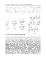
Fig. 2. The output from the execution of the program “MLay.m” is displayed. R = 0.9204.
The refractive index and the thickness for input are
“rfr = [1.0 2.5 1.5 2.5 1.5 2.5 1.0];”
“thick = wvl./(4*rfr);”
“thick(1) = 0;”
“thick(Nm) = 0;”.
The result of execution is shown as in Fig. 2. In this simulation, the layer structure is
comprised of air, 2.5 pairs of TiO2/SiO2, and air from the incident medium. The final
reflectivity of the layers is about 92 %. The thickness of each layer is a quarter wavelength to
obtain the high reflection. The circular marks represent the position of the interfaces so that
the reigon between the marks corresponds to a single layer. Since the incident medium and
the final medium have zero thickness, the number of layers seen in Fig. 2 is only 4 instead of
6. The peak intensity decreases as the light penetrates the layers.
Organic Light Emitting Diode – Material, Process and Devices
280
0 0.05 0.1 0.15 0.2 0.25 0.3 0.35
0
1
2
3
4
5
6
7
8
9
10
ETL
EML
HTLITO
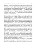
Fig. 3. The output from the execution of the program “MLay.m” is displayed. R = 0.8706.
The refractive index and the thickness for input are
“rfr = [1.5 2.13 1.87 1.94 1.75 0.644+5.28i];”
“thick = [0 0.09 0.177 0.048 0.029 0];”
In order to analyze of the real OLED device, the refractive index and the thickness are
replaced by those of the OLED. The layers used in the simulation are overcoat, indium tin
oxide(ITO), hole transport layer(HTL), emission layer(EML) and aluminum cathode,
respectively. The title of each layer is typed in as an annotation at the bottom of the plot
between the circular marks, which represent the boundaries of each layer. The light is
supposed to be incident on the overcoat layer first.
In the design of the OLED cavity, the position of the emission layer is important since it
affects the emission efficiency of the device. As in Fig. 3, the emission layer occupies the
peak position of the intensity profile. It means that the optical density of state is high over
the emission layer and the electron transition rate is also high. If the emission layer is placed
around the node of the intensity profile, the spontaneous emission is suppressed rather than
enhanced. Quantum mechanics states that the radiation probability is proportional to the
electron transition probability and the optical density of states(Gasiorowicz, 1984). If the two
atoms have the same transition probability, but have different optical density of states,
which generally depends on the position of the atom inside the cavity, the resultant
transition rate comes to be determined by the optical density around the atom. This kind of
enhancement is often observed in the design of a micro-cavity laser such as vertical-cavity
surface-emitting laser(VCSEL). Therefore, the OLED engineer should pay attention to
controlling the thickness of the layers so that the emission layer is positioned at the peak of
the intensity, otherwise, he will lose optical efficiency.
Micro-Cavity in Organic Light-Emitting Diode
281
Eq. 8 can be modified into a bit more complicated form in order to handle oblique incidence
angle, polarization, dispersion, user-friendly interface, and so on. But, all these variations
stick around the same boundary conditions under different circumstances. The
generalization of the program is left for the fun of the reader.
3. Tunable micro-cavity in OLED
In the former section, the MATLAB program calculates the electric field profile inside the
conventional OLED device. The multi-layer structure naturally forms the cavity through the
reflections at the interfaces of the cathode, organic layers, anode, and so on. The bandgap
difference between the materials causes the index differences and this index mismatch
accompanies reflections. Therefore, it is very hard to get rid of the reflections at the interfaces
and the cavity effect inside the OLED. In this section, we present the method of how to more
actively use this interference in order to control the emission wavelength of the white OLED.
The design of a strong cavity can be realized by reinforcing the bottom mirror. In the
conventional OLED, the anode usually consists of a transparent conductive oxide like
indium zinc oxide(IZO) and it plays a role of bottom mirror. The higher index contrast
between IZO and the neighboring layers increases the reflectivity at the interfaces. Since Al
cathode already keeps high reflectance over the visible wavelength, increasing the
reflectivity of the bottom mirror can strengthens the cavity effect. At first thought, a metallic
layer at the bottom can be used to make a strong cavity. However, metals usually have a
very high imaginary index, which means strong absorption. In this case, the light generated
inside cannot escape the cavity unless the metallic layer is very thin. As matter of fact, very
thin layer of silver can forms the strong cavity in OLED. However, the thin layer is not easy
to deposit maintaining the uniformity of the device.
In this article, we present the results in which distributed Bragg reflector(DBR) comprises
the bottom mirror of the cavity. The DBR is simply a periodic stack of dielectrics with
different refractive index. The thickness is usually a quarter wavelength to increase the
reflectivity. The schematic diagram of the micro-cavity consisting of DBR is displayed as in
Fig. 4. Compared to the structure used in the simulation for Fig. 3, the bottom side has three
additional layers of IZO/SiO2/IZO. Although these three layers seem to lack the number of
layers comparing to the DBR in VCSELs, this number of layers are adequate for controlling
the emission property of the OLED.
Fig. 4. The structure of strong cavity used for controlling the emission wavelength of white
OLED.
Organic Light Emitting Diode – Material, Process and Devices
282
It is worthy to note that the thickness of the second IZO layer is variable to tune the resonant
wavelength. In general, the resonant peak moves depending on the thickness of the cavity.
In a conventional cavity, the central layer such as the emission layer in this structure is
adjusted to change the resonance. However, the emission layer in OLED is kind of sensitive
layer which should be untouched due to the optimization of the emission characteristics.
Instead, the extra tuning layer is added to the anode layer to affect the cavity length. This
technique is often used to make a tunable VCSEL(Ju et al, 2000).
The analysis of the cavity effect needs the information on the spectral reflectance. The
program used in the previous section should be modified to calculate the reflectivity over a
range of wavelength instead of a single wavelength. The modified code is shown below.
( FILE: MLay_a2.m )
clear all;
global Nm;
global rfr;
global MA;
global Efl;
wvli=0.4;
wvlf=0.7;
wvlwd=0.002;
rfr = [1.5 2.1+0.016i 1.5 2.1+0.016i 2.13 1.87 1.94 1.75 0.644+5.28i];
thick = [0 0.073 0.089 0.040 0.09 0.117 0.048 0.029 0];
Nm = length(rfr);
thick(1) = 0;
thick(Nm) = 0;
wvll = [wvli:wvlwd:wvlf];
Rcurve=[];
for n=1:length(wvll)
wvl=wvll(n);
kv = 2*pi*rfr/wvl;
MA = @(k) [exp(i*kv(k)*thick(k)), exp(-i*kv(k)*thick(k));
rfr(k)*exp(i*kv(k)*thick(k)), -rfr(k)*exp(-i*kv(k)*thick(k))];
vEf = Ef(1);
Rcurve = [Rcurve; [wvl*1000, abs(vEf(2)/vEf(1))^2]];
end
plot(Rcurve(:, 1), Rcurve(:,2));
grid on;
xlabel('wavelength(nm)');
ylabel('reflectivity');
The outcome of the program is displayed in Fig. 5. This modelling assumes that the tuning
layer is 40 nm IZO. The reflectance has its resonance at 540 nm. The rapid drop of
reflectivity at the center indicates that the transmission is high at this wavelength. This is a
typical behavior of a cavity made with two highly reflecting mirrors. Although the mirror
reflects the incident light, the constructive interference inside the cavity under resonant
condition makes the transmission very high. Although the simulation calculates the
reflectivity curve, it also provides the information about the spectral emission. The
transmittance or the spectral emission can be obtained by subtracting reflectance from 1.
Therefore, the spontaneous emission other than the resonant wavelength is suppressed by
Micro-Cavity in Organic Light-Emitting Diode
283
the cavity. If the emission layer contains the RGB emission layer as in white OLED, the
resonant wavelength determines the emission color of the pixel. As for 40 nm IZO tuning
layer, the cavity allows the pixel to emit 540 nm with spectral width of 50 nm, which is
narrower than the natural spectral width of the green emission in OLED. In other words, the
use of cavity enhances the color purity of the emission.
For the most part, OLED includes color filter(CF) layer to reduce the spectral width and
improve color gamut. However, the reduction of spectral width comes through the
absorption of the light energy outside the spectral window of the pigment. It suffers energy
loss for the sake of enhancement in color purity. On the contrary, the spectral narrowing
induced by cavity effect doesn’t suffer energy loss since it originates from the change of
optical modes inside the cavity, not the absorption process. Therefore, the cavity in OLED
increases the transmission efficiency through CF by narrowing the spectral width without
energy loss.
400 450 500 550 600 650 700
0.55
0.6
0.65
0.7
0.75
0.8
0.85
0.9
0.95
wavelength(nm)
reflectivity
Fig. 5. The reflectivity curve is calculated when the tuning layer is IZO and 40 nm thick.
Furthermore, the resonance in this DBR cavity varies as a function of the thickness of the
tuning layer. As the thickness of the tuning layer increases, the resonance shifts toward long
wavelength. When the tuning IZO layer is 100 nm, the resonance goes from 540 nm to 620
nm and the secondary resonance appears at 460 nm as seen from Fig. 6. The thicker tuning
layer provides the way to narrow the spectral width of blue and red emission. It means that
one tuning layer can create two resonances at the same time. In this way, two types of
tuning layers can make the interference filter for RGB and enhance the optical efficiency in
OLED. The reflectivity curves with different tuning layer and thickness are shown in Fig. 7.
It shows that SiNx also function as a tuning layer but with smaller spontaneous
enhancement due to its smaller index.
Organic Light Emitting Diode – Material, Process and Devices
284
400 450 500 550 600 650 700
0.5
0.55
0.6
0.65
0.7
0.75
0.8
0.85
0.9
wavelength(nm)
reflectivity
Fig. 6. The reflectivity curve is calculated when the tuning layer is IZO and 100 nm thick.
400 450 500 550 600 650 700
0.5
0.55
0.6
0.65
0.7
0.75
0.8
0.85
0.9
0.95
wavelength(nm)
reflectivity
SiNx 40 nm
SiNx 100 nm
IZO 4 0 nm
IZO 100 nm
Fig. 7. The reflectivity curves are plotted. The tuning layers are (a) 40 nm SiNx, (b) 100 nm
SiNx, (c) 40 nm IZO, and (d) 100 nm IZO, respectively.
Based on this idea, the practical OLED devices were fabricated and demonstrated(Lee et al,
2009a). The schematic diagram of OLED structure with DBR cavities and tuning layers are
Micro-Cavity in Organic Light-Emitting Diode
285
illustrated in Fig. 8. We fabricated RGBW AMOLED panels with the above optical designs
and the conventional CF used in LCDs (color gamut = 72%). The panels showed a color
gamut in the range of 100–110% NTSC. On the other hand, panels with no micro-cavity
design had a color gamut of only 75%. Another benefit was increased light output through
the CF. With micro-cavity designs, the CF transmission ratio increased to 40% from 27%.
The light output from R, G, and B subpixels increased by about 50%.
Fig. 8. A micro-cavity design of a RGBW bottom-emitting AMOLED. OC stands for
overcoat. The RGB subpixels have DBR (IZO or ITO and SiOx), a filter common for RGB
(SiNx), and another filter (IZO or ITO) for R and B subpixels. The W subpixels do not have
DBR in order to avoid the spectral modification and dependence on the viewing angle.
4. FDTD analysis for OLED(Lee et al, 2009b)
As matter of fact, the multi-layer theory deals with one dimensional problem since it assume
that the physical situation doesn’t change for the translation movement in the plane of the
layers. This assumption is quite good for the conventional OLED device. The functional
layers of submicron thickness are deposited on large area glass, whose lateral dimension is
virtually infinite compared to the thickness. However, suppose the OLED structure is made
on the curved surface or the wavy substrate for some reason. From this point, the problem
becomes two dimensional or three dimensional one, which is not within the scope of
multi-layer theory. Then, what kinds of theoretical tools are available to the designer?
Even though ray tracing is most frequently used algorithm to calculate the optical
property of the system, it lacks capability of handling interference and sub-wavelength
feature like thin film. FDTD can be a good option although it takes much time to compute
the electric field inside the cavity. The computation time increases rapidly as the feature
size and the dimension increases. Therefore, the analysis should be carefully planned to
reduce the computation time and obtain the goal of calculation at the same time. In this
section we present an example of analyzing the undulated cavity of the OLED structure
using FDTD method.
Organic Light Emitting Diode – Material, Process and Devices
286
Fig. 9. Principles of tuning resonance in undulated micro-cavity
The main purpose of the undulated micro-cavity is to modify spectrum with the change of
undulation profile. The physical mechanism of tuning resonance in undulated cavity is
illustrated in Fig. 9. When the OLED layers are deposited over the undulated profile of the
overcoat (OC) layer, the thickness of evaporation normal to substrate is uniform over the
whole device. However, the thickness normal to the slope is proportional to cos if the angle
between the slope and the substrate is . In addition, the emission is not normal to the slope,
which leads to the blue shift of resonance peak proportional to the cos As a result, the
resonant wavelength of an undulated micro-cavity is proportional to cos
2
The angle of slope is controlled by varying the amount of UV exposure in the lithography
process. More UV exposure causes a deeper trench in OC layer after development process.
The reflow process smoothen the rectangular profile into a curved surface. In general, the
angle of the slope increases as the UV exposure increases. The experimental results are
displayed in Fig. 10. The emission peak has changed with the increase of UV exposure
time. The red curve represents the micro-cavity tuned to the R and B pixel showing the
strong peaks around the red and blue wavelength. The increased UV exposure moves the
peak to green wavelength which is optimized for G pixel in OLED display as seen in the
brown curve.
In a real device, the UV exposure is controlled by the opening size of the mask pattern. Since
the opening size of the mask pattern can be set to different values for RGB pixels, the
resonance frequency of each pixel can be tuned simultaneously by one step
photolithography. It greatly alleviates the processing burden which typically comes with the
micro-cavity devices used for multi-colors.
In order to analyze the resonance shift and other optical properties of an undulated micro-
cavity, the FDTD method and the permittivity profile as shown in Fig. 11 were used. In this
structure, the micro-cavity largely consists of the organic layers sandwiched between DBR
and a cathode. From the bottom-most layer, DBR layers are comprised of 70 nm SiNx, 90 nm
SiO2, 35 nm SiNx, 90 nm indium zinc oxide (IZO). The organic layers are 120 nm hole
transport layer, 50 nm emission layer, 30 nm electron transport layer. Lastly, the thickness of
Aluminum cathode is 200 nm on the top. The region below distributed Bragg reflector
(DBR) is assumed to be filled with OC layer. The permittivties used for SiNx, SiO2, IZO,
Micro-Cavity in Organic Light-Emitting Diode
287
hole transport layer, emission layer, electron transport layer and Alumium are 3.61, 2.25,
4.23, 3.74, 3.51, 2.94 and 0.06+I 3.50 respectively. The undulation profile is modeled using a
sine wave form. The period and the height of the sine wave determine the angle of the slope
in the undulated micro-cavity.
Fig. 10. Emission spectra of white OLED with variation of UV exposure time. The red line
and brown line corresponds to 4 s and 6 s of exposure time, respectively.
Fig. 11. Permittivity profile of undulated micro-cavity in OLEDs. Period = 5.0 m,
height = 0.6 m.
Organic Light Emitting Diode – Material, Process and Devices
288
For measuring the spectrum change, the dipole is allowed to oscillate for a short time. Since
the short pulse acts as a broad band source, it can be a good light source to characterize the
frequency response of the micro-cavity. The detector apart from the dipole source collects
the wave emitted at a certain angle. The Fourier transformed output of the collected wave is
divided by the Fourier transformed input to give frequency response at each wavelength. In
this way, the spectrum change of the micro-cavity can be analyzed.
(a)
(b)
Micro-Cavity in Organic Light-Emitting Diode
289
(c)
Fig. 12. Spectrum of dipole emission in undulated micro-cavity with various heights and
emission angle; Period = 5.0 m, height = (a) 0.0 m, (b) 0.2 m, and (c) 0.4 m, emission
angle = 0
O
(solid), 30
O
(thick solid), 60
O
(dotted).
When the dipole is placed in the middle of the slope of the undulation profile, the spectrum
shows blue shifts as the height increases as seen in Fig. 12. It agrees with the experimental
results observed in the real device(Lee et al, 2009a). The dipole is placed in the middle of the
slope since the slope region is the brightest part of the device. Thermal evaporation of organic
material results in uniform thickness in the vertical direction. It means that the thickness
normal to the surface is the smallest near the slope. The reduced thickness of organic layers
also reduced the electrical resistance in the part, which leads to the current crowding near the
slope. Therefore, locating the dipole in the middle of slope is reasonable to explain the blue
shift of the spectrum. Otherwise, the dipole oscillation near peak or valley gives less change to
the resonance peak. The resonance peak at normal angle shifts from 525 nm to 510 nm when
the height changes from 0.0 m to 0.4 m. Since the angle of the slope is roughly 9 degrees at
the height of 0.4 m, the amount of blue shift may be explained by cos
2
dependence. As
explained before, this angle dependency can be ascribed to the layer thinning due to the
slanted evaporation and oblique resonance condition, each of which has cos dependency.
The internal physical mechanisms of undulated micro-cavity that controls the emission
wavelength in OLEDs was investigated. The finite-difference-domain method is applied to a
previously manufactured OLED design featuring optical structure on a wavy over-coat layer.
The emission spectrum shows blue shift of 15 nm when the height of undulation changes from
0.0 m to 0.4 m with the period fixed at 5.0 m. The blue shift is also observed in the
experiment and the amount of shift in the simulation complies with cos
2
dependence.
5. Acknowledgment
This work was supported by Samsung Electronics Corporation. This work was supported
by National Research Foundation of Korea Grant funded by the Korean Government(2009-
0071253).
Organic Light Emitting Diode – Material, Process and Devices
290
6. References
Born M and Wolf M, Principles of Optics, 6th Ed., ISBN 0-02-946146-4, p.55 (1989)
Fowles G R,
Introduction to Modern Optics, 2nd Ed., ISBN 0-03-089404-2, Chapter 4 (1975).
Gasiorowicz S, Quantum physics, Chapter 22 (1984)
Ju Y G, Lofgreen D, Fiore A, Hu S Y, Hegblom E, Louderback D, Sjolund O, Huntington A,
Coldren L A, "Densely packed pie shaped vertical-cavity surface-emitting laser
array incorporating a tapered one-dimensional wet oxidation",
IEEE Photonics
Technology Letters
, vol.12, no. 5, p.462-464, May 30 (2000)
Lee B W, Ju Y G, Hwang Y I, Lee H Y, Kim C W, Lee J S, and Souk J H, "Micro-cavity design
of bottom-emitting AMOLED with white OLED and RGBW color filters for 100%
color gamut",
Journal of the Society for Information Display, Vol. 17, Issue 2, pp. 151-
157 (2009a) Feb.
Lee B W, Ju Y G, "Analysis of undulated micro-cavity in organic light-emitting diodes",
Optical and quantum electronics, vol. 41, Issue 8, pp. 627-633 (2009b)