Superconductivity Theory and Applications Part 11 doc
Bạn đang xem bản rút gọn của tài liệu. Xem và tải ngay bản đầy đủ của tài liệu tại đây (2.39 MB, 25 trang )
11
Development of
Josephson Voltage Standards
Johannes Kohlmann and Ralf Behr
Physikalisch-Technische Bundesanstalt (PTB)
Germany
1. Introduction
Exciting applications of superconductivity are based on the macroscopic quantum state
which exists in a superconductor. In this chapter we investigate the behaviour of junctions
consisting of two weakly coupled superconductors. These junctions are nowadays called
Josephson junctions
1
(Josephson, 1962). The macroscopic quantum state results in an excep-
tional behaviour of these Josephson junctions. They are the basis for various applications in
superconductive electronics (cf. Anders et al, 2010), e.g. in the field of metrology for high-
precision measurements. The most significant representative of a metrological application is
the Josephson voltage standard. This quantum standard enables the reference of the unit of
voltage, the volt, just to physical constants. It is nowadays used in many laboratories world-
wide for high-precision voltage measurements. The main component of each modern
Josephson voltage standard is the highly integrated series array consisting of tens of
thousands of Josephson junctions fabricated in thin-film technology.
While Josephson junctions are conceptually simple, nearly 50 years of developments were
needed to progress from single junctions delivering a few millivolt at most to highly inte-
grated series arrays containing more than 10,000 or even 100,000 junctions. These large
series arrays enable the generation of dc and ac voltages at the 10 V level, which is relevant
for most applications. Conventional Josephson voltage standards based on underdamped
Josephson junctions are used for dc applications. The increasing interest in highly precise ac
voltages has stimulated different attempts to develop measurement tools on the basis of
Josephson arrays for ac applications, namely programmable Josephson voltage standards
containing binary-divided arrays and pulse-driven Josephson voltage standards both based
on overdamped Josephson junctions. This chapter describes the development of these
modern dc and ac Josephson voltage standards as well as their fundamentals and applica-
tions. The development and use of Josephson voltage standards have also been described
recently in several review papers (amongst others: Niemeyer, 1998; Hamilton, 2000;
Yoshida, 2000; Behr et al., 2002; Kohlmann et al., 2003; Benz & Hamilton, 2004; Jeanneret &
Benz, 2009).
1
When Brian D. Josephson was a 22-year-old graduate student at Trinity College in Cambridge, UK, he
theoretically derived equations for the current and voltage across a junction consisting of two weakly
coupled superconductors in 1962. His discovery won him a share of the 1973 Nobel Prize in Physics.
Superconductivity – Theory and Applications
240
2. Fundamentals - the Josephson effects
A superconductor as a macroscopic object is quantum mechanically described by a macro-
scopic wavefunction. This macroscopic wavefunction is an important aspect of the BCS
theory of superconductivity named after the authors Bardeen, Cooper, and Schrieffer
2
(1957). Brian Josephson investigated the behaviour of two weakly coupled superconductors
on the basis of the BCS theory a few years after its publication (Josephson, 1962). He
predicted two effects due to the tunnelling of Cooper pairs across the connection, i.e. a
coupling of the macroscopic wavefunction of the two superconductors: (1) a dc super-
current I = I
c
sin
can flow across this junction (I
c
denotes the critical current and
the
phase between the macroscopic wavefunction of the two superconductors); (2) an ac super-
current of frequency f
J
= (2e/h)V occurs if the junction is operated at a non-zero voltage V,
i.e. a Josephson junction is an oscillator (e is the elementary charge and h is Planck’s
constant). Irradiation of the junction by external microwaves of frequency f vice versa
produces constant-voltage steps due to the phase locking of the Josephson oscillator by the
external oscillator: V
n
= n(h/2e)f (n = 1, 2, 3, … denotes the integer step number). As an
illustration, the generation of constant-voltage steps can also be described as a specific
transfer of flux quanta
0
= h/2e through the Josephson junction. The irradiation of the
Josephson junctions with external microwaves of frequency f effects this specific transfer
and produces constant-voltage steps V
n
:
V
n
= n
0
f (1)
The Josephson effect thus reduces the reproduction of voltages to the determination of a
frequency, which can be finely controlled with high precision and accurately referenced to
atomic clocks. The constant-voltage steps were observed soon after by Shapiro (1963). A
single Josephson junction operated at the first-order constant-voltage step generates about
145 µV, when irradiated by 70 GHz microwaves. Highly integrated junction series arrays are
therefore needed to achieve practical output voltages up to 1 V or 10 V.
The frequency range for the best operation of Josephson junctions is determined by their dy-
namic characteristics. The most important parameter is the characteristic voltage V
c
= I
c
R
n
(R
n
denotes the normal state resistance of the junctions). The characteristic voltage is related
to the characteristic frequency by equation (1): f
c
= (2e/h)V
c
= (2e/h)I
c
R
n
.
The dynamics of a Josephson junction is often investigated using the resistively-capacitively-
shunted-junction (RCSJ) model (Stewart, 1968; McCumber, 1968). Within this model, the real
Josephson junction is described as a parallel shunting of an ohmic resistance R, a capacitance
C, and an ideal Josephson element. In the linear approximation, the resonance frequency is
given by the plasma frequency f
p
= (ej
c
/hC
s
)
1/2
(j
c
denotes the critical current density,
C
s
= C/A the specific junction capacitance, and A the junction area). Details of the behaviour
depend on the kind of junction, which can be characterized by the dimensionless
McCumber parameter
c
= Q
2
being equal to the square of the quality factor Q = 2f
p
RC of
the junction. Underdamped junctions with
c
> 1 show a hysteretic current-voltage charac-
teristic, overdamped junctions with
c
1 a non-hysteretic one as schematically shown in
Fig. 1. Detailed descriptions of the Josephson effects and Josephson junctions have been
2
Bardeen, Cooper, and Schrieffer were awarded the 1972 Nobel Prize in Physics for their theory of
superconductivity.
Development of Josephson Voltage Standards
241
given in several reviews (e.g. Josephson, 1965; Kautz, 1992; Rogalla, 1998) and textbooks
(e.g. Barone & Paternò, 1982; Likharev, 1986; Kadin, 1999).
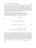
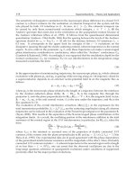
Fig. 1. Schematic current-voltage characteristic of underdamped (left) and overdamped
(right) Josephson junctions without (top) and with (bottom) microwave irradiation. Some
constant-voltage steps are marked.
3. Realization of Josephson junctions and series arrays
A Josephson junction is composed of two weakly coupled superconductors. While Joseph-
son (1962) originally investigated the tunnelling of Cooper pairs through a barrier, i.e. an in-
sulator, he also mentioned that similar effects should occur when two superconductors are
separated by a thin normal region. These two junction types are nowadays indeed the most
important ones for Josephson junctions, namely the so-called SIS junctions and SNS
junctions, respectively (S: Superconductor, I: Insulator, N: Normal metal). SIS junctions are
typically underdamped junctions, while SNS junctions are overdamped ones. Moreover,
further possibilities for the realization of Josephson junctions exist such as e.g. SINIS junc-
tions, grain boundary junctions (especially for high-temperature superconductors), and
junctions consisting of two superconductors connected by a narrow constriction. As junc-
tions for Josephson voltage standards are mainly based on SIS, SNS, or SINIS junctions,
these types will be described in more detail in the following. The fabrication of the inte-
grated circuits containing these junctions is based on the same main steps; the fabrication
processes differ only in detail.
3.1 Fabrication process
The development of Josephson voltage standards is intimately connected with improve-
ments of the fabrication technology for series arrays. The fabrication process should be as
simple and reliable as possible, and must be realized in thin-film technology, in order to
enable the fabrication of highly integrated circuits containing thousands of junctions in a
similar way to in the semiconductor industry. Josephson junctions and the first series arrays
in the 1980s were fabricated in lead/lead alloy technology (cf. Niemeyer et al, 1984); but the
Superconductivity – Theory and Applications
242
main problem was the susceptibility to damage of the lead alloy circuits by humidity and
thermal cycling. The main important breakthrough in the development of a more robust
fabrication process was the invention of the Nb/Al-Al
2
O
3
technology by Gurvitch et al
(1983). This technology combines the use of the durable and chemically stable metal Nb
with the high critical temperature of about 9.2 K, the outstanding covering of thin Al layers
on Nb, and the formation of a very homogeneous and stable oxide of Al by thermal oxi-
dation. The adaptation of this process and several improvements made possible the fabrica-
tion of voltage standard arrays consisting of Nb/Al-Al
2
O
3
/Nb Josephson junctions in 1986
(Niemeyer et al, 1986). Nowadays, all Josephson arrays for voltage standard applications
are fabricated in processes fundamentally based on this invention.
Sputtered Nb is typically used at present for the superconducting layers and NbN in case of
operation at 10 K, respectively. Dielectric layers are realized by SiO
2
. Lithography is made
optically or by electron-beam depending on the dimensions of the structure and its com-
plexity. The different layers are patterned by adapted fluorine-based dry etching processes.
For a reliable process, the trilayer or multilayer defining the junctions are deposited as a
sandwich structure without breaking the vacuum. This process requires an additional wiring
layer for connecting neighbouring junctions by a window technology. The barrier material is
also sputtered; if the barrier includes an oxide, a metallic layer is thermally oxidized. SIS
junctions contain an Al
2
O
3
barrier realized by thermal oxidation of the Al layer. SINIS
junctions consist of a multilayer of Nb/Al
2
O
3
/Al/Al
2
O
3
/Nb. SIS junctions are typically
operated at around 70 GHz. The characteristic voltage of SINIS junctions can be tuned over a
wide range enabling operation either at frequencies around 15 GHz or around 70 GHz.
Different materials have been investigated and used for the N layer of SNS junctions. As the
specific resistance of most metals is rather low, high-resistive materials are preferred in
order to increase the characteristic voltage. Most SNS junctions are therefore operated at
frequencies between 10 GHz and 20 GHz. The high resistivity for the N layer is reached by
binary alloys as PdAu (Benz et al, 1997), HfTi (Hagedorn et al, 2006), or MoSi
2
(Chong et al,
2005). Junctions containing an N layer of Ti (Schubert et al, 2001a) or TiN (Yamamori et al,
2008) have also been realized. Recently, a new type of junction has increasingly gained in
importance: its barrier consists of a semiconductor such as Si doped with a metal and being
near a metal insulator transition (Baek et al, 2006). Although these junctions behave like
SNS junctions, they are more their own class of junctions and sometimes called SI’S
junctions. A promising version of these SI’S junctions is realized by an amorphous Si barrier
doped by Nb. Nb and Si are co-sputtered from two sputter targets; the Nb content is varied
by adjusting the power for sputtering.
The thickness of the superconducting layers is typically above about 150 nm and therefore
roughly twice the superconducting penetration depth at least. The superconducting layers
are consequently both thick enough, to ensure appropriate microwave behaviour, and thin
enough, to allow reliable thin-film processes. The barrier is between 10 nm and 30 nm thick
depending on the details of the material. Stacked junctions have also been investigated in
order to increase the integration density of junctions. They contain multilayers of super-
conducting Nb and barrier material. Adapted etching processes guarantee vertical edges
and thus an identical size of each individual junction in order to yield homogeneous
electrical parameters of the junction stacks. Arrays of double- and triple-stacked junctions
have successfully been fabricated delivering output voltages between a few volts and even
10 V (Chong et al, 2005; Yamamori et al, 2008).
Development of Josephson Voltage Standards
243
Fig. 2. Cross section of a microstripline.
3.2 Designs - a brief survey
An important requirement for the design of the circuits is the uniform microwave power
distribution over all Josephson junctions in order to generate wide and stable constant-volt-
age steps. The step width of the constant-voltage steps depends on the applied microwave
power; in some cases, the dependence is given by a Bessel function (Kautz, 1992 & 1995). A
uniform power distribution is achieved by the integration of the Josephson junctions into
adapted microwave transmission lines. Most modern Josephson voltage standards are
based on one of three different microwave lines: a low-impedance microstrip line (cf. Fig. 2),
a 50 coplanar waveguide transmission line (CPW) (cf. Fig. 9), and a 50 coplanar stripline
(CPS). The microstrip line caused the breakthrough for the first version of modern voltage
standards, i.e. the conventional Josephson voltage standard (cf. Niemeyer et al, 1984), and is
mainly used to date for circuits operated in the frequency range around 73 GHz. Circuits
based on CPWs have been introduced for programmable Josephson voltage standards
operated in the frequency range from 10 GHz to 20 GHz (cf. Benz, 1995). Coplanar strip-
lines were first used for conventional voltage standards operated at 75 GHz (Schubert et al,
2001b). CPW and CPS offer the advantage of a rather simple required fabrication technol-
ogy compared to the microstrip line that needs an additional ground plane and a dielectric
layer. An advantage of the microstrip line is that it enables a rather simple possibility of
splitting a single high-frequency line in two parallel ones; this splitting can be performed
several times. Each microwave branch is terminated by a matched lossy microwave line
that serves as a load. Microwave reflections are therefore suppressed, which consequently
provides a uniform microwave distribution by avoiding standing waves.
Most conventional dc Josephson voltage standards are based on microstrip line designs.
The design of programmable Josephson voltage standards depends on the frequency range
for their operation. Most programmable standards operated around 73 GHz are also based
on microstrip line designs. Circuits for operation between 10 GHz and 20 GHz use CPWs
(cf. Benz et al, 1997; Dresselhaus et al, 2009). The design is determined in detail by the high-
frequency behaviour of the Josephson junctions.
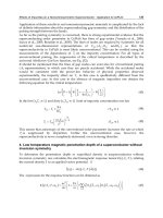
Fig. 3 shows, as an example, the PTB design of a 10 V SNS array for operation at 70 GHz and
this is briefly described in the following. An antipodal finline taper serves as an antenna. It
connects the microstrip line, containing the Josephson junctions, to the E-band rectangular
Superconductivity – Theory and Applications
244
Fig. 3. Design of a 10 V SNS Josephson series array developed at PTB. The array consist of
69,632 junctions embedded into 128 parallel low-impedance microstriplines. The length and
width of a single junctions is 6 µm x 20 µm. The size of the total chip is 24 mm x 10 mm.
waveguide while simultaneously matching the impedance of the waveguide (about 520 )
to that of the microstrip line (about 5 ). The microstrip line is split in several stages
forming parallel branches. The design of conventional 10 V circuits contains two stages
resulting in four parallel branches. The design of programmable 1 V (10 V) circuits consists
of 6 (7) stages forming 64 (128) parallel branches. The reason for these differences can be
understood by using the RCSJ model (cf. section 2). For SIS junctions, the ohmic resistance
R
n
is of the order of 50 , while the impedance of the capacitive branch Z
d
= 1/(2fC) is of
the order of 50 m for a junction capacitance of 50 pF. High-frequency currents therefore
flow mainly capacitively resulting in a very low attenuation of the microwave power from
about 1 dB/1,000 junctions to 2 dB/1,000 junctions. Each branch can therefore contain a lot
of junctions (about 3,500 junctions in the real design) without loosing a uniform microwave
power distribution to each junction. The conditions are completely different for over-
damped SINIS junctions. Now, R
n
and Z
d
are comparable (about 50 m each) leading to the
significant dissipation of the microwave current and thus to a significant attenuation of the
microwave power of about 50 dB/1,000 junctions (Schulze et al, 1999). The high attenuation
is, however, compensated in part by an active contribution of the junctions; the junctions act
as oscillators. The single branches of programmable series arrays consist therefore of 128
junctions (1 V design) and up to 582 junctions (10 V design), respectively. Overdamped SNS
junctions integrated into a low-ohmic microstrip line show similar behaviour, as a signifi-
cant part of the microwave is dissipated resistively.
Another situation is found for overdamped SNS junctions embedded into the centre line of a
CPW. The ratio of the low junction impedance to the 50 impedance of the CPW leads to a
situation which is similar to that of the microstrip line for conventional SIS arrays: Atten-
uation of the microwave power is low, because the junctions are loosely linked to the CPW.
Each branch can therefore contain more junctions than in the microstrip line designs.
Typical numbers for 1 V (10 V) arrays are 8 (32) branches with 4096 (8400) junctions each
(Benz et al, 1997; Burroughs et al, 2009a).
Development of Josephson Voltage Standards
245
4. DC measurements - conventional Josephson voltage standards
While at the beginning of Josephson voltage standards the voltage of a single junction in the
millivolt range was used as a reference (cf. Niemeyer, 1998; Hamilton, 2000), the chapter of
modern Josephson voltage standards was opened by two new ideas: First, Levinson et al
(1977) suggested the use of highly underdamped junctions with hysteretic current-voltage
characteristics producing constant-voltage steps whose current ranges overlap one another
for small bias currents. A single bias current source can consequently be used to bias all
junctions of a series array on the quantized constant-voltage steps. Secondly, the Josephson
junctions are embedded into an adapted microwave transmission line resulting in first 1 V
arrays realized by Niemeyer et al (1984). Because of this arrangement, the Josephson
junction series array is connected in series for the dc bias and acts as a microstrip line at rf
frequencies. As the microwave power is mainly capacitively coupled to the underdamped
junctions, the rf attenuation of the series array is very low, therefore, enabling uniform rf
bias of all junctions.
Since the mid 1980s Josephson voltage standards based on these concepts have been
available. Underdamped Josephson junctions are typically realized by SIS junctions (S:
Superconductor, I: Insulator). Large series arrays of Josephson junctions are needed to reach
the voltage level essential for real applications, namely 1 V or especially 10 V. A 10 V series
array typically contains between about 14,000 and 20,000 Josephson junctions depending on
the details of the specific design. The circuits developed and fabricated at PTB consist of
about 14,000 junctions distributed to four parallel low-impedance microstrip-lines. Typical
arrays show under 70 GHz microwave irradiation a step width above 20 µA, best arrays up
to 50 µA. This kind of so-called conventional Josephson voltage standard has been success-
fully operated to date for dc applications in many national, industrial, and military
standards labs around the world. They are now commercially offered by two companies.
3
In spite of their very successful use for dc applications, conventional Josephson voltage
standards have two important drawbacks due to the ambiguity of the constant-voltage
steps: First, they do not enable switching rapidly and reliably between different specific
steps. Secondly, the constant-voltage steps are only metastable so that electromagnetic
interference can cause spontaneous switching between steps.
5. From DC to AC - programmable Josephson voltage standards
As described in the previous section, conventional Josephson voltage standards are operated
very successfully for dc applications. The increasing interest in rapidly switching arrays
and in highly precise ac voltages stimulated research activities in the mid 1990s to develop
measurement tools based on Josephson junctions to meet these requirements. Different
attempts have been suggested and partly realized. The main important ones are pro-
grammable voltage standards based on binary-divided arrays (cf. 5.1), pulse-driven arrays
(cf. 5.3), and a d/a converter based on the dynamic logic of processing single flux quanta
(SFQ) (cf. Semenov & Polyakov, 2001). In the following, the first two versions are described
in more detail, as most research activities are presently focused on these two, and promising
results have meanwhile been demonstrated. Both are intended to extend the use of high-
precision Josephson voltage standards from dc to ac.
3
Hypres Inc., USA: www.hypres.com and Supracon AG, Germany: www.supracon.com.
Superconductivity – Theory and Applications
246
5.1 Programmable voltage standards based on binary-divided arrays
The limitations of conventional Josephson voltage standards are mainly due to the over-
lapping steps resulting from the hysteretic current-voltage characteristic of underdamped
Josephson junctions. Therefore, Josephson junctions showing a non-hysteretic current-
voltage characteristic have been investigated. Such behaviour is shown by an overdamped
Josephson junction. The current voltage-characteristic is non-hysteretic and remains single-
valued under microwave irradiation (cf. Fig. 1). The constant-voltage steps are
consequently inherently stable and can rapidly be selected by external biasing. All junctions
are operated on the same constant-voltage step (typically the first one) in contrast to those of
conventional standards, which are operated at the fourth to fifth step as average. The
number of junctions necessary to attain a given voltage must be increased correspondingly.
The series array of junctions must additionally be divided into segments in order to enable
the generation of different voltage levels. The Josephson array is hence operated as a multi-
bit digital-to-analogue (d/a) converter based on a series array of overdamped Josephson
junctions divided into segments containing numbers of junctions belonging e.g. to a binary
sequence of independently biased smaller arrays (cf. Fig. 4). Any integral number of
constant-voltage steps permitted by that sequence can consequently be generated by these
arrays, often called programmable Josephson voltage standards.
A programmable Josephson voltage standard was suggested and demonstrated for the first
time by Hamilton et al (1995). In that case 2,048 junctions of an array containing 8,192
externally shunted SIS junctions were operated at 75 GHz and delivered an output voltage
of about 300 mV. As the critical current and consequently the step width are limited to a
few hundred microamperes due to design restrictions of externally shunted SIS arrays, and
a design for these junctions is rather complex and challenging, other junction types have
subsequently been investigated. The final breakthrough of programmable voltage stand-
ards was enabled by the implementation of SNS junctions (Benz, 1995), whereupon calcu-
lations by Kautz (1995) had given important hints for their realization (S: Superconductor,
N: Normal metal).
The first practical 1 V arrays were realized by Benz et al (1997). A total of 32,768 SNS
junctions containing PdAu as the normal metal were embedded into the middle of a
coplanar waveguide transmission line (CPW) with an impedance of 50 . The width of the
constant-voltage steps exceeds 1 mA under microwave operation around 16 GHz. This low
microwave frequency gives rise to a drawback of SNS junctions, namely the large number of
junctions needed to reach the 1 V (32,000 junctions) or the 10 V level (300,000 junctions).
f
rf
>
Output voltage
x xx xxxx xxxxxxxx
V
1
2V
1
4V
1
8V
1
~ ~ ~ ~
Computer controlled bias sources
Load
f
rf
>
Output voltage
x xx xxxx xxxxxxxx
V
1
2V
1
4V
1
8V
1
~ ~ ~ ~
Computer controlled bias sources
Load
Fig. 4. Schematic design of a programmable Josephson voltage standard based on a binary-
divided series array of Josephson junctions shown as X. The array is operated as multi-bit
digital-to analogue converter.
Development of Josephson Voltage Standards
247
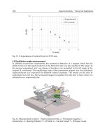
Fig. 5. Photo of a 10 V programmable Josephson junction series array.
This huge number of junctions causes enormous challenges for the microwave design and
for the fabrication technology. The use of stacked junctions was subsequently investigated
in order to handle this huge number of junctions. For example, arrays of double- and triple-
stacked junctions containing MoSi
2
barriers were developed generating voltages up to 3.9 V
(Chong et al, 2005).
Other kinds of junctions have therefore been investigated, in order to reach characteristic
voltages of about 150 µV which allows operation at 70 GHz. A successful development has
been SINIS junctions consisting of a multilayer superconductor-insulator-normal metal-in-
sulator-superconductor originally investigated for electronic applications (Maezawa & Shoji,
1997; Sugiyama et al, 1997). The first small series arrays and 1 V arrays were subsequently
fabricated (Schulze et al, 1998; Behr et al, 1999). The 1 V arrays contain 8,192 junctions. The
first 10 V arrays consisting of 69,120 junctions were also developed shortly afterwards
(Schulze et al, 2000) and later significantly improved (Mueller et al, 2007).
In spite of their successful use, a serious drawback of SINIS junctions is their sensitivity to
particular steps during fabrication often resulting in a few shorted junctions of a SINIS
series array (typically between 0 and 10 of 10,000 junctions) probably due to the very thin in-
sulating oxide barriers (cf. Mueller et al, 2009). The search for more robust barrier materials
led to an amorphous silicon layer doped with a metal such as niobium (Baek et al, 2006).
The niobium content is tuned to a value near a metal-insulator transition observed at a
niobium concentration of about 11.5% (Hertel et al, 1983). This region combining a high
resistivity and a sufficient conductivity allows the fabrication of 1 V and 10 V arrays for
operation at 70 GHz (Mueller et al, 2009). Fig. 5 shows a photo of a 10 V programmable
Josephson junction series array. Measurements showed that a few 10 V arrays consisting of
69,632 junctions had been realized without any shorted junction, which was never achieved
using SINIS junctions. Step widths above 1 mA have meanwhile been reached (cf. Fig. 6).
This junction type currently enables the most reliable fabrication process.
Series arrays of junctions with an amorphous Nb
x
Si
1-x
barrier were originally used for
circuits operated around 15 GHz. Burroughs et al (2009a) developed 10 V arrays containing
three-junction stacks with 268,800 junctions arranged in 32 parallel branches. Constant-
voltage steps at 10 V were generated under microwave irradiation between about 18 GHz
and 20 GHz. Tapered CPWs have been used in order to assure a homogeneous microwave
power distribution along 8,400 junctions in each branch (Dresselhaus et al, 2009).
Some other kinds of junctions have also been investigated. While most Josephson arrays are
operated in liquid helium at 4.2 K, Yamamori et al (2006) developed arrays for operation at
Superconductivity – Theory and Applications
248
-7 -6 -5 -4 -3 -2 -1 0 1 2 3 4 5 6 7
-20
-15
-10
-5
0
5
10
15
20
Voltage (V)
Current (mA)
1 mA
1 V
f = 71.28 GHz
@ 60 mW
Current / mA
Voltage / V
-7 -6 -5 -4 -3 -2 -1 0 1 2 3 4 5 6 7
-20
-15
-10
-5
0
5
10
15
20
Voltage (V)
Current (mA)
1 mA
1 V
f = 71.28 GHz
@ 60 mW
Current / mA
Voltage / V
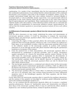
Fig. 6. Current-voltage characteristic of a 10 V programmable Josephson junction series
array without (red) and with (blue) 70 GHz microwave irradiation. The inset shows the
constant-voltage step at the 10 V level with high resolution.
temperatures around 10 K by using NbN for the superconducting layers and TiN for the
barrier. The arrays consisting of more than 500,000 junctions for operation at 16 GHz gen-
erate voltages up to 17 V (Yamamori et al, 2008). Another version for 70 GHz operation is
based on an improved design of 3315 externally shunted SIS junctions operated on the third-
order constant-voltage step (Hassel et al, 2005). Recently 1 V SNIS arrays were developed
by Lacquaniti et al (2011) using a slightly oxidized thick Al layer (up to 100 nm) as a barrier.
5.2 Applications using binary-divided programmable Josephson voltage standards
Conventional Josephson voltage standards are used for dc applications, namely to calibrate
voltage references e.g. Weston elements or Zener references, and to measure the linearity of
voltmeters. The Josephson voltage standards in many countries around the world have
been verified by international comparisons. The Bureau International des Poids et Mesures
(BIPM) developed a travelling Josephson voltage standard for performing direct com-
parisons, typically achieving uncertainties of 1 part in 10
10
(Wood & Solve, 2009). The
advantage of programmable Josephson voltage standards over conventional ones is given in
the speed required to adjust a precise voltage. In direct comparisons using a null-detector at
room temperature, the main uncertainty source is the type-A uncertainty from the null-
detector’s noise. In speeding up a comparison the uncertainty can be reduced by a factor n
where n is the number of polarity reversals. Using two programmable 10 V Josephson
voltage standards, the polarity reversing procedure can be easily automated. This has been
demonstrated (Palafox et al, 2009) with a type-A uncertainty of 3 parts in 10
12
.
Binary-divided Josephson arrays were originally developed aiming at d/a converters with
fundamental accuracy as a source for ac calibrations. Fig. 7 shows a step-wise approximated
sine wave. It was tested to calibrate thermal transfer standards (Hamilton et al, 1995). The
Development of Josephson Voltage Standards
249
synthesized waveforms contain small parts of undefined voltages during transients between
well-defined quantized voltage levels. To improve achievable uncertainties, the transients
have been made faster and faster, from 1 µs (Hamilton et al, 1997) to below 100 ns (Williams
et al, 2007). Measurements on thermal transfer standards have shown possible uncertainties
better than 1 µV/V for frequencies below 200 Hz (Behr et al, 2005) but for higher frequencies
transients dominate uncertainties. Different error analyses (Lee et al, 2009; Burroughs et al,
2009b) confirm that transients will make it very difficult to further improve the pre-
dictability of these quantized voltage sources as the transients depend on too many para-
meters like applied bias current, microwave power or helium levels in the dewar. The only
way for further improvements seems to require specific assumptions for the device under
test (Séron et al, 2011).
Due to this fundamental limitation from transients the idea came up of combining the step-
wise approximated Josephson waveforms with sampling methods. In a first experiment, a
sampling voltmeter was calibrated by sampling the quantized voltage levels (Ihlenfeld et al,
2005). Later stepwise approximated waveforms and sampling were used to demonstrate an
ac quantum voltmeter measuring ac voltage differentially (Behr et al, 2007). Both methods
are used nowadays to link a power standard directly to a quantum basis (Palafox et al, 2007
& 2009; Rüfenacht et al, 2009). By introducing faster sampling systems and pre-amplifiers
for a wide range of ac applications like ac-dc transfer calibrations, this idea has been further
improved. As here the Josephson system is acting as a voltage reference, it also allows com-
bining it with an external ac source traced back or locked to the Josephson voltage
(Rüfenacht et al, 2011). For certain applications this is favourable as ac sources can drive a
current to low-impedance devices. Driving a current from a Josephson voltage standard is
very limited as typically step widths are not much larger than 1 mA, accordingly the
impedance must be larger than 10 k for 10 V Josephson arrays.
Towards higher frequencies sampling methods are limited due to the bandwidth of a/d
converters which are affected by fast voltage edges in stepwise approximated waveforms
and a decreasing aperture time for raising frequencies. The frequency limit is determined
by the number of samples taken for a period. When using rectangular waveforms, i.e. the
Fig. 7. Synthesis of a step-wise approximated 50 Hz sine wave using a 10 V Josephson
junction series array.
Superconductivity – Theory and Applications
250
minimum number of samples, frequencies up to 6 kHz have been used to calibrate
impedance ratios (Lee et al, 2011), while typically 16 to 256 samples reduce the bandwidth to
clearly below 1 kHz (Kim et al, 2010).
Another way to minimize the effect of transients is to use the rectangular waveforms and to
just look at the fundamental tone of the waveform. Practically this is easy when a lock-in
amplifier is used as a null-detector. Internally the lock-in amplifier multiplies the rectangu-
lar waveform with a sine wave heavily weighting the quantized plateaus and almost neg-
lecting the transients (Jeanneret et al, 2010). The influence of the transients is suppressed to
below parts in 10
8
which is being utilized fully for impedance ratio measurements (Lee et al,
2010).
However, the only way to completely avoid transients at all is to use the so-called pulse-
driven Josephson arbitrary waveform synthesizer. This method is described in detail in the
next paragraph.
5.3 Pulse-driven arrays
The interest in quantum-accurate ac waveform synthesis led to the development of another
version of Josephson voltage standards for ac applications (Benz & Hamilton, 1996). Those
Josephson voltage standards described so far are operated by sinusoidal microwaves in
order to effect the transfer of flux quanta through Josephson junctions. This works well, if
the operating frequency is close to the characteristic frequency of the junctions (cf. chapter 2
and equation (1); Kautz, 1992 & 1995). A modulation of the output voltage by changing the
frequency of the irradiated microwaves over a wide frequency range is therefore not possi-
ble. Nevertheless, a direct time-dependent manipulation of the flux quanta transfer seems
to be very promising for an ac voltage standard, in order to enable the synthesis of spectrally
pure waveforms and to avoid those drawbacks related to the multi-bit d/a converter
operation of binary-divided arrays.
Indeed, the limitations of sinusoidal operation do not appear, if Josephson junctions are
operated by a train of short current pulses as shown first by calculations (Monaco, 1990).
The width of the constant-voltage steps is nearly independent of the pulse repetition fre-
quency between zero and the characteristic frequency, if rise and fall time of the pulses are
short compared to the characteristic frequency (10 GHz corresponds to 100 ps). The train of
pulses then determines the number of flux quanta transferred through the Josephson
junctions at any time. The waveform to be generated is encoded in the pulse train. A high
pulse repetition rate generates high voltages; the voltage decreases with decreasing pulse
repetition rate. Fig. 8 schematically shows the principle of operation. Arbitrary output
waveforms can be synthesized by modulating the pulse train using a pulse pattern gen-
erator; sometimes this version of pulse-driven Josephson arrays is therefore also called
Josephson Arbitrary Waveform Synthesizer (JAWS).
The pulse train is typically created by the use of a second-order sigma-delta (SD) modula-
tion (cf. Benz et al, 1998; Kieler et al, 2009). This procedure shifts the quantization noise to
high frequencies; noise contributions are then removed by appropriate filtering. The
Josephson junctions act as a quantizer due to the transfer of flux quanta. Spectrally pure
waveforms are synthesized that way with higher harmonics suppressed by more than
100 dB (cf. Benz et al, 2009a; Kieler et al, 2009). The easiest way to prove perfect quanti-
zation of a synthesized signal is to generate and measure a sine wave, whose spectrum
should show a single tone without any additional harmonics.
Development of Josephson Voltage Standards
251
Fig. 8. Schematic of operation for pulse-driven arrays.
Pulse-driven arrays need overdamped Josephson junctions, which have predominantly been
realized by SNS junctions. Different materials have been used for the barrier such as e.g.
PdAu (Benz et al, 2001), HfTi (Hagedorn et al, 2006) or Nb
x
Si
1-x
(Benz et al, 2007). SINIS
junctions have also been investigated (Kohlmann et al, 2006).
Pulse-driven arrays were suggested and first demonstrated by Benz and Hamilton (1996).
An array of 512 junctions generated constant-voltage steps up to 265 µV under operation by
unipolar pulses with a repetition frequency up to 250 MHz. Continuous enhancements
gradually improved the spectra of the synthesized signals and increased the output volt-
ages. The first important steps ahead have been, amongst others: a code generator allowing
a pulse repetition frequency of about 10 GHz (Benz et al, 1998) and the use of a bipolar drive
signal (Benz et al, 1999). The overdamped Josephson junctions are embedded into the
middle of a coplanar waveguide transmission line (CPW). As the pulses consist of broad-
band frequency components ranging from dc to about 30 GHz, a complicated microwave
assembly is required in order to enable the transmission of these broadband signals.
The broadband pulse drive including dc and low-frequency components causes additional
requirements in operation compared to sinusoidal driven arrays. The dc component must
be delivered to the array, e.g. by a direct connection to the code generator. A resistive
microwave termination at the end of the CPW would produce an unwanted common mode
voltage; in order to avoid this common mode voltage, the initially used arrays were
designed as lumped elements, whose junction series array are directly grounded. Finally, a
simple splitting of the array in parallel microwave paths is not possible.
The configuration as lumped arrays, however, limits the length of the series array, which
must be short compared to the wavelength
of the highest significant frequency. A length
of typically
/8 ensures a uniform distribution of the high-frequency power comprised in
the pulses to all junctions (
12 mm for a frequency of 10 GHz within a CPW on a Si
wafer). The number of junctions is therefore restricted to about 2,000 at most using sub-µm
junction technology (Hagedorn et al, 2006). A promising suggestion for increasing the
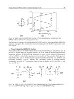
number of junctions is their arrangement within a meander-like structure as shown in Fig. 9
(Kieler et al, 2007a). Arrays containing more than 10,000 junctions were realized; the
Superconductivity – Theory and Applications
252
Fig. 9. Design of a Josephson junction series array for pulse drive (left). The scanning
electron microscope pictures (right) show a part of the middle of the CPW containing
Josephson junctions arranged in a meander-like structure.
synthesis of spectrally pure waveforms with low distortion has, however, been successful
only in part so far (Kieler et al, 2007b).
A way of avoiding the limitations related to lumped arrays and of solving the common
mode problem is the ac-coupling technique for the operation of Josephson arrays (Benz et al,
2001). Here, the broadband pulse drive is split into high-frequency and low-frequency
signals (split around 10 MHz). While the high-frequency signal is capacitively coupled to
the series array, the low-frequency part is separately applied by an additional compensation
bias. A resistive microwave termination can now be placed at the end of the array without
causing common-mode voltages. Therefore, extended series arrays can be used, which con-
sequently enables a significant increase in the number of junctions. Further improvements
resulted in output voltages up to 275 mV rms (Benz et al, 2009a). Two arrays containing
6,400 junctions each were simultaneously operated by using the data output and the com-
plementary data output of the code generator, respectively. Higher harmonics are sup-
pressed by more than 110 dB (Benz et al, 2007 & 2009a).
In spite of these very encouraging results the synthesis of voltages at 1 V or more remains very
challenging. It will probably require a parallel operation of several arrays using adapted
electronics (Benz et al, 1999 & 2009a) or the approach for the operation of multiple arrays that
has been suggested by Kohlmann et al (2006). It is based on balanced photodiodes arranged at
each array and operated by short optical pulses (Williams et al, 2004). The operation of
Josephson arrays by optical pulses has also been investigated by Urano et al (2010).
The pulse train is typically provided by a commercial pulse pattern generator (bitstream
generator). Fifteen years ago these generators just delivered unipolar pulses. As bipolar
signals are preferred for metrological applications, and the peak-to-peak voltage is simply
doubled, ways and means have been investigated to generate bipolar pulse trains even with
unipolar pulses. The initially used procedure for this purpose is the suitable superposition
of a high-frequency sine wave and a two-level digital signal as first proposed by Benz et al
Development of Josephson Voltage Standards
253
Fig. 10. Synthesized 1.25 kHz sine wave (top) and its frequency spectrum (bottom). Higher
harmonics are suppressed by 118 dBc. The small signal at about 8.8 kHz is not related to the
synthesized signal, as it is also present at the noise level when no waveform is synthesized.
(1999). Today the direct generation of bipolar pulses using a three-level code generator is
easy as corresponding instruments have recently been made available (van den Brom et al,
2008). Now the measurement setup is less complex (cf. Fig. 8) and more temporally stable
when this three-level code generator is used (van den Brom et al, 2007 & 2008). Different
waveforms were synthesized over a wide frequency range from about 150 Hz to above
100 kHz using arrays containing nearly 4,800 junctions; higher harmonics are suppressed up
to 118 dBc (Kieler et al, 2010). In addition, the operation margins of the arrays were signifi-
cantly improved, and 200 mV (rms) signals at 1 kHz were synthesized by simultaneously
operating two arrays containing 5120 junctions each (Houtzager et al, 2009).
A comparison between the output voltages of a pulse-driven and a binary divided Joseph-
son voltage standard at 8 mV showed an excellent agreement of both systems within a
relative deviation of 5 10
-7
(Kohlmann et al, 2009).
The arbitrary perfect waveforms synthesized by pulse-driven arrays are useful for different
metrological applications. First of all, pulse-driven arrays were used as synthesizers for
arbitrary waveforms up to 100 kHz with very pure frequency spectra and quantum-accurate
voltages (cf. Benz et al, 2009a; Houtzager et al, 2009; Kieler et al, 2009). Then, pulse-driven
arrays were utilized for calibrations of thermal converters and transfer standards, which are
well-established devices in ac metrology (cf. Lipe et al, 2008; Benz et al, 2009a). Single- or
multi-tone signals were, in addition, used for the characterization of electronic components
like filters or a/d converters (cf. Toonen and Benz, 2009). The use of pulse-driven arrays
was also suggested in combination with a binary-divided array; the spectrum of the pulse-
driven array is adjusted to modify the spectrum of the 1 V or 10 V signal generated by the
binary divided array (Kohlmann et al, 2007). In addition, pulse-driven arrays provide the
opportunity for synthesizing a calculable pseudo-noise waveform consisting of a comb of
random-phase harmonics each having identical voltage amplitude. A low-voltage version
of this noise source is used in a quantum-based Johnson noise thermometry system to
measure the voltage noise of the resistor, and thus its temperature (Benz et al, 2009b).
Superconductivity – Theory and Applications
254
6. Conclusions
100 years after the discovery of superconductivity and nearly 50 years after the discovery of
the Josephson effect, Josephson voltage standards play an essential role in electrical metro-
logy and high-precision voltage measurements. The significant progress of the fabrication
technology has been a major prerequisite for the development of large series arrays for
Josephson voltage standards containing tens of thousands Josephson junctions. Conven-
tional 10 V Josephson voltage standards are well established for dc measurements and com-
mercially available. Programmable voltage standards opened up the world of ac applica-
tions and have, hence, been the next step in the exciting story of the applications of the
Josephson effect in metrology. While 1 V arrays are meanwhile fabricated routinely, the first
10 V arrays containing tens or even hundreds of thousands of Josephson junctions are now
available. Conventional Josephson voltage standards will be replaced in the future more
and more by these programmable Josephson voltage standards, as they are easier to operate
and provide exciting additional possibilities and applications. The synthesis of real quan-
tum-based ac voltages is enabled by pulse-driven arrays. Very promising results have been
achieved; output voltages of about 275 mV were synthesized with higher harmonics sup-
pressed by about 120 dBc. However, the aim to generate 1 V ac voltages is very challenging
due to the complex operation by short current pulses. The value of ac Josephson voltage
standards has successfully been demonstrated in initial experiments. Further developments
will establish these Josephson voltage standards as a quantum basis for ac metrology.
7. Acknowledgment
The authors would like to thank the Josephson voltage standard team at PTB.
The work within this EURAMET joint research project leading to these results was sup-
ported in part by the European Community’s Seventh Framework Programme, ERA-NET
Plus, under Grant Agreement 217257 (JoSy project).
8. References
Anders, S.; Blamire, M.G.; Buchholz, F Im. et al (2010). European roadmap on supercon-
ductive electronics – status and perspectives. Physica C, Vol.470, No.23-24, (Decem-
ber 2010) pp. 2079-2126
Baek, B.; Dresselhaus, P.D. & Benz, S.P. (2006). Co-sputtered amorphous Nb
x
Si
1-x
barriers for
Josephson-junction circuits. IEEE Transactions on Applied Superconductivity, Vol.16,
No.4 (December 2006) pp. 1966-1970
Bardeen, J.; Cooper, L.N. & Schrieffer, J.R. (1957). Theory of Superconductivity. Physical
Review, Vol. 108, No. 5, (December 1957) pp. 1175-1204
Barone A. & Paterno G. (1982). Physics and applications of Josephson effect, John Wiley &
Sons, ISBN 0-471-01469-9, New York, USA
Behr, R.; Schulze, H.; Müller, F.; Kohlmann, J. & Niemeyer J. (1999). Josephson arrays at
70 GHz for conventional and programmable voltage standards. IEEE Transactions
on Instrumentation and Measurement, Vol.48, No.2, (April 1999) pp. 270-273
Behr, R.; Müller, F. & Kohlmann, J. (2002). Josephson junction arrays for voltage standards,
In: Studies of Josephson junction arrays II: Studies of high temperature superconductors,
Development of Josephson Voltage Standards
255
Vol.40, A.V. Narlikar (Ed.), 155-184, Nova Science Publishers, ISBN 1-59033-204-0,
Hauppauge, NY, USA
Behr, R.; Williams, J.M ; Patel, P.; Janssen, T.J.B.M.; Funck, T. & Klonz, M. (2005). Synthesis
of precision AC waveforms using a SINIS Josephson junction array. IEEE Trans-
actions on Instrumentation and Measurement, Vol.54, No.2, (April 2005) pp. 612-615
Behr, R.; Palafox L.; Ramm G.; Moser H. & Melcher, J. (2007). Direct comparison of
Josephson waveforms using an AC quantum voltmeter. IEEE Transactions on
Instrumentation and Measurement, Vol.56, No.2, (April 2007) pp. 235-238
Benz, S.P. (1995). Superconductor-normal-superconductor junctions for programmable volt-
age standards. Applied Physics Letters, Vol.67, No.18, (October 1995) pp. 2714-2716
Benz, S.P. & Hamilton, C.A. (1996). A pulse-driven programmable Josephson voltage stand-
ard. Applied Physics Letters, Vol.68, No.22, (May 1996) pp. 3171-3173
Benz, S.P.; Hamilton, C.A.; Burroughs, C.J.; Harvey, T.E. & Christian, L.A. (1997). Stable 1-
volt programmable voltage standard. Applied Physics Letters, Vol.71, No.13, (Sep-
tember 1997) pp. 1866-1868
Benz, S.P.; Hamilton, C.A.; Burroughs, C.J.; Harvey, T.E.; Christian, L.A. & Przybysz, J.X.
(1998). Pulse-driven Josephson digital/analog converter. IEEE Transactions on
Applied Superconductivity, Vol.8, No.2, (June 1998) pp. 42-47
Benz, S.P.; Hamilton, C.A.; Burroughs, C.J. & Harvey, T.E. (1999). AC and DC bipolar
voltage source using quantized pulses. IEEE Transactions on Instrumentation and
Measurement, Vol.48, No.2, (April 1999) pp. 266-269
Benz, S.P.; Burroughs, C.J. & Dresselhaus, P.D. (2001). AC coupling technique for Josephson
waveform synthesis. IEEE Transactions on Applied Superconductivity, Vol.11, No.1,
(March 2001) pp. 612-616
Benz, S.P. & Hamilton, C.A. (2004). Application of the Josephson effect to voltage metrology.
Proceedings of the IEEE, Vol.92, No.10, (October 2004) pp. 1617-1629
Benz, S.P.; Dresselhaus, P.D.; Burroughs, C.J. & Bergren, N.F. (2007). Precision measure-
ments using a 300 mV Josephson arbitrary waveform synthesizer. IEEE Transactions
on Applied Superconductivity, Vol.17, No.2, (June 2007) pp. 864-869
Benz, S.P.; Dresselhaus, P.D.; Rüfenacht, A.; Bergren, N.F.; Kinard, J.R. & Landim, R.P.
(2009a). Progress toward a 1 V pulse-driven AC Josephson voltage standard. IEEE
Transactions on Instrumentation and Measurement, Vol.58, No.4, (April 2009) pp. 838-
843
Benz, S.P.; Jifeng Qu; Rogalla, H.; White, D.R.; Dresselhaus, P.D.; Tew, W.L. & Sae Woo Nam
(2009b). Improvements in the NIST Johnson noise thermometry system. IEEE Trans-
actions on Instrumentation and Measurement, Vol.58, No.4, (April 2009) pp. 884-890
van den Brom, H.E.; Houtzager, E.; Chevtchenko, O.; Wende, G.; Schubert, M.; May, T.;
Meyer, H G.; Kieler, O. & Kohlmann, J. (2007). Synthesis of sinusoidal signals with
a Josephson arbitrary waveform synthesizer. Superconductor Science and Technology,
Vol.20, No.5 (May 2007) pp. 413-417
van den Brom, H.E.; Houtzager, E.; Brinkmeier, B.E.R. & Chevtchenko, O.A. (2008). Bipolar
pulse-drive electronics for a Josephson arbitrary waveform synthesizer. IEEE Trans-
actions on Instrumentation and Measurement, Vol.57, No.2, (February 2008) pp. 428-
431
Superconductivity – Theory and Applications
256
Burroughs, C.J.; Rüfenacht, A.; Dresselhaus, P.D.; Benz, S.P. & Elsbury, M.M. (2009a). A
10 Volt “turnkey” programmable Josephson voltage standard for DC and stepwise-
approximated waveforms. NCSLI Measure, Vol.4, No.3, (September 2009) pp. 70-75
Burroughs, C.J.; Rüfenacht, A.; Benz, S.P. & Dresselhaus, P.D. (2009b). Systematic error
analysis of stepwise-approximated AC waveforms generated by programmable
Josephson voltage standards. IEEE Transactions on Instrumentation and Measurement,
Vol.58, No.2, (April 2009) pp. 761-767
Chong, Y.; Burroughs, C.J.; Dresselhaus, P.D.; Hadacek, N.; Yamamori, H. & Benz, S.P.
(2005). Practical high-resolution programmable Josephson voltage standards using
double- and triple-stacked MoSi
2
-barrier junctions. IEEE Transactions on Applied
Superconductivity, Vol.15, No.2, (June 2005) pp. 461-464
Dresselhaus, P.D.; Elsbury, M.M. & Benz, S.P. (2009). Tapered transmission lines with
dissipative junctions. IEEE Transactions on Applied Superconductivity, Vol.19, No.3,
(June 2009) pp. 993-998
Gurvitch, M.; Washington, M.A. & Huggins, H.A. (1983). High quality refractory Josephson
tunnel junctions utilizing thin aluminum layers. Applied Physics Letters, Vol.42,
No.5, (March 1983) pp. 472-474
Hagedorn, D.; Kieler, O.; Dolata, R.; Behr, R.; Müller, F.; Kohlmann, J. & Niemeyer, J. (2006).
Modified fabrication of planar sub-µm superconductor-normal metal-supercon-
ductor Josephson junctions for use in a Josephson Arbitrary Waveform Synthesizer.
Superconductor Science and Technology, Vol.19, No.4, (April 2006) pp. 294-298
Hamilton, C.A.; Burroughs, C.J. & Kautz, R.L. (1995). Josephson D/A converter with fun-
damental accuracy. IEEE Transactions on Instrumentation and Measurement, Vol.44,
No.2, (April 1995) pp. 223-225
Hamilton, C.A.; Burroughs, C.J.; Benz, S.P. & Kinard, J.R. (1996). AC Josephson voltage
standard: progress report. IEEE Transactions on Instrumentation and Measurement,
Vol.46, No.2, (April 1997) pp. 224-228
Hamilton, C.A. (2000). Josephson voltage standards. Review of Scientific Instruments, Vol.71,
No.10, (October 2000) pp. 3611-2623
Hassel, J.; Helistö, P.; Grönberg, L.; Seppä, H.; Nissilä, J. & Kemppinen, A. (2005). Stimulated
power generation in ES-SIS junction arrays. IEEE Transactions on Instrumentation and
Measurement, Vol.54, No.2, (April 2005) pp. 632-635
Hertel, G.; Bishop, D.J.; Spencer, E.G.; Rowell, J.M. & Dynes, R.C. (1983). Tunneling and
transport measurements at the metal-insulator transition of amorphous Nb:Si.
Physical Review Letters, Vol.50, No.10, (March 1983) pp. 743-746
Houtzager, E.; Benz, S.P. & van den Brom, H.E. (2009). Operating margins for a pulse-driven
Josephson arbitrary waveform synthesizer using a ternary bit-stream generator.
IEEE Transactions on Instrumentation and Measurement, Vol.58, No.4, (April 2009) pp.
775-780
Ihlenfeld, W.G.K.; Mohns, E.; Behr, R; Williams, J.M.; Patel, P.; Ramm G. & Bachmair, H.
(2005). Characterization of a high-resolution analogue-to-digital converter with an
AC Josephson voltage source. IEEE Transactions on Instrumentation and Measurement,
Vol.54, No.2, (April 2005) pp. 649-652
Jeanneret, B. & Benz, S.P. (2009). Applications of the Josephson effect in electrical metrology.
The European Physical Journal Special Topics, Vol.172, (June 2009) pp. 181-206
Development of Josephson Voltage Standards
257
Jeanneret, B.; Overney, F.; Rüfenacht, A. & Nissilä, J. (2010). Strong attenuation of the
transients’ effect in square waves synthesized with a programmable Josephson
voltage standard. IEEE Transactions on Instrumentation and Measurement, Vol.59,
No.7, (July 2010) pp. 1894-1899
Josephson, B.D. (1962). Possible new effects in superconducting tunneling. Physics Letters,
Vol.1, No.7, (July 1962) pp. 251-253
Josephson, B.D. (1965). Supercurrents through barriers. Advances in Physics, Vol.14, No.56,
(October 1965) pp. 419-451
Kadin, A.M. (1999). Introduction to superconducting circuits, Wiley, ISBN 0-471-31432-3,
New York, USA
Kautz, R.L. (1992). Design and operation of series-array Josephson voltage standards, In:
Metrology at the Frontiers of Physics and Technology, L. Crovini and T.J. Quinn, (Eds.),
259-296, North-Holland, ISBN 0-444-89770-4, Amsterdam, The Netherlands
Kautz, R.L. (1995). Shapiro steps in large-area metallic-barrier Josephson junctions. Journal of
Applied Physics, Vol.78, No. 9, (November 1995) pp. 5811-5819
Kieler, O.F.; Kohlmann, J.; Behr, R.; Müller, F.; Palafox, L. & Niemeyer, J. (2007a) SNS
Josephson junction series arrays for the Josephson arbitrary waveform synthesizer.
IEEE Transactions on Applied Superconductivity, Vol.17, No.2, (June 2007) pp. 187-190
Kieler, O.F.; Kohlmann, J. & Müller, F. (2007b). Improved design of superconductor/normal
conductor/superconductor Josephson junction series arrays for an ac Josephson
voltage standard. Superconductor Science and Technology, Vol.20, No.11, (November
2007) pp. S318-S322
Kieler, O.F.; Iuzzolino, R. & Kohlmann, J. (2009). Sub-µm SNS Josephson junction arrays for
the Josephson arbitrary waveform synthesizer. IEEE Transactions on Applied Super-
conductivity, Vol.19, No.3, (June 2009) pp. 230-233
Kieler, O.F.; Schleussner, D.; Kohlmann, J. & Behr, R. (2010). Josephson arbitrary waveform
synthesizer for analysis of AC components, In: 2010 Conference on Precision Electro-
magnetic Measurements (CPEM 2010), Yang Sup Song (Ed.), 157-158, Institute of
Electrical and Electronic Engineers, ISBN 978-1-4244-6794-5, Piscataway, NJ, USA
Kim, M S.; Kim, K T.; Kim, W.S.; Chong, Y. & Kwon, S W. (2010). Analog-to-digital
conversion for low frequency waveforms based on the Josephson voltage standard.
Measurement Science and Technology, Vol.21, No.11, (November 2010) 115102 (6 pp.)
Kohlmann, J.; Behr, R. & Funck, T. (2003). Josephson voltage standards. Measurement Science
and Technology, Vol.14, No.8, (August 2003) pp. 1216-1228
Kohlmann, J.; Müller, F.; Behr, R.; Hagedorn, D.; Kieler, O.; Palafox, L. & Niemeyer, J. (2006).
Development of Josephson junction series arrays for synthesis of AC voltages and
arbitrary waveforms. Journal of Physics: Conference Series, Vol.43, No.1, (2006) pp.
1385-1388
Kohlmann, J.; Müller, F.; Kieler, O.; Behr, R.; Palafox, L.; Kahmann, M. & Niemeyer, J. (2007).
Josephson series arrays for programmable 10-V SINIS Josephson voltage standards
and for Josephson arbitrary waveform synthesizers based on SNS junctions. IEEE
Transactions on Instrumentation and Measurement, Vol.56, No.2, (April 2007) pp. 472-
475
Kohlmann, J.; Kieler, O.F.; Iuzzolino, R.; Lee, J.; Behr, R.; Egeling, B. & Müller, F. (2009).
Development and investigation of SNS Josephson arrays for the Josephson arbi-
Superconductivity – Theory and Applications
258
trary waveform synthesizer. IEEE Transactions on Instrumentation and Measurement,
Vol.58, No.4, (April 2009) pp. 797-802
Lacquaniti, V.; De Leo, N.; Fretto, M.; Sosso, A.; Müller F. & Kohlmann, J. (2011). 1 V pro-
grammable voltage standards based on SNIS Josephson junction series arrays.
Superconductor Science and Technology, Vol.24, No.4, (April 2011) 045004 (4 pp.)
Lee, J.; Behr, R.; Katkov, A. & Palafox, L. (2009). Error contributions in stepwise synthesized
Josephson sine waves. IEEE Transactions on Instrumentation and Measurement, Vol.58,
No.2, (April 2009) pp. 803-808
Lee, J.; Schurr, J.; Nissilä, J.; Palafox, L. & Behr, R. (2010). The Josephson two-terminal-pair
impedance bridge. Metrologia Vol. 47, No.4, (August 2010) pp. 453-459
Lee, J.; Schurr, J.; Nissilä, J.; Palafox, L.; Behr, R. & Kibble, B. (2011). Impedance measure-
ments with programmable Josephson systems. IEEE Transactions on Instrumentation
and Measurement, to be published (2011)
Levinson, M.T.; Chiao, R.Y.; Feldman, M.J. & Tucker, B.A. (1977). An inverse ac Josephson
effect voltage standard. Applied Physics Letters, Vol.31, No.11, (December 1977) pp.
776-778
Likharev, K.K. (1986). Dynamics of Josephson junctions and circuits, Gordon & Breach, ISBN
2-881-24042-9, New York, USA
Lipe, T.E.; Kinard, J.R.; Tang, Y H.; Benz, S.P.; Burroughs, C.J. & Dresselhaus, P.D. (2008).
Thermal voltage converter calibrations using a quantum ac standard. Metrologia,
Vol.45, No.3, (June 2008) pp. 275-280
Maezawa, M. & Shoji, A. (1997). Overdamped Josephson junctions with
Nb/AlO
x
/Al/AlO
x
/Nb structure for integrated circuit application. Applied Physics
Letters, Vol.70, No.26, (June 1997) pp. 3603-3605
McCumber, D.E. (1968). Effect of ac impedance on dc voltage-current characteristics of
superconductor weak-link junctions. Journal of Applied Physics, Vol.39, No. 7, (June
1968) pp. 3113-3118
Monaco, R. (1990). Enhanced ac Josephson effect. Journal of Applied Physics, Vol.68, No.2,
(July 1990) pp. 679-687
Mueller, F.; Behr, R.; Palafox, L.; Kohlmann, J.; Wendisch, R. & Krasnopolin, I. (2007). Im-
proved 10 V SINIS series arrays for applications in AC voltage metrology. IEEE
Transactions on Applied Superconductivity, Vol.17, No.2, (June 2007) pp. 649-652
Mueller, F.; Behr, R.; Weimann, T.; Palafox, L.; Olaya, D.; Dresselhaus, P.D. & Benz, S.P.
(2009). 1 V and 10 V SNS programmable voltage standards for 70 GHz. IEEE
Transactions on Applied Superconductivity, Vol.19, No.3, (June 2009) pp. 981-986
Niemeyer, J.; Hinken, J.H. & Kautz, R.L. (1984). Microwave-induced constant voltage steps
at one volt from a series array of Josephson junctions. Applied Physics Letters, Vol.45,
No.4, (August 1984) pp. 478-480
Niemeyer, J.; Sakamoto, Y.; Vollmer, E.; Hinken, J.H.; Shoji, A.; Nakagawa, H.; Takada, S. &
Kosaka, S. (1986). Nb/Al-oxide/Nb and NbN/MgO/NbN tunnel junctions in large
series arrays for voltage standards. Japanese Journal of Applied Physics, Vol.25, No.5,
(May 1986) pp. L343-L345
Niemeyer, J. (1998). Josephson voltage standards, In: Handbook of Applied Superconductivity,
B. Seeber, (Ed.), 1813-1834, Institute of Physics Publishing, ISBN 0-750-30377-8,
Bristol, UK
Development of Josephson Voltage Standards
259
Palafox, L.; Ramm, G.; Behr, R.; Kürten Ihlenfeld, W.G. & Moser H. (2007). Primary AC
power standard based on programmable Josephson arrays. IEEE Transactions on
Instrumentation and Measurement, Vol.56, No.2, (April 2007) pp. 534-537
Palafox, L.; Behr, R.; Ihlenfeld, W.G.K.; Müller, F.; Mohns, E.; Seckelmann, M. & Ahlers, F.
(2009). The Josephson effect based primary power standard at PTB: progress report.
IEEE Transactions on Instrumentation and Measurement, Vol.58, No.4, (April 2009) pp.
1049-1053
Rogalla, H. (1998). Josephson junctions, In: Handbook of Applied Superconductivity, B. Seeber,
(Ed.), 1759-1775, Institute of Physics Publishing, ISBN 0-750-30377-8, Bristol, UK
Rüfenacht, A.; Burroughs, C.J.; Benz, S.P.; Dresselhaus, P.D.; Waltrip, B. & Nelson, T.L.
(2009). Precision differential sampling measurements of low-frequency synthesized
sine waves with an AC programmable Josephson voltage standard. IEEE Trans-
actions on Instrumentation and Measurement, Vol.58, No.4, (April 2009) pp. 809-815
Rüfenacht, A.; Overney, F.; Mortara, A. & Jeanneret, B. (2011). Thermal transfer standard
validation of the Josephson-voltage-standard-locked sine wave synthesizer. IEEE
Transactions on Instrumentation and Measurement, to be published (2011)
Schubert, M.; Fritzsch, L.; Wende, G. & Meyer H G. (2001a). SNS junction on Nb-Ti base for
microwave circuits. IEEE Transactions on Applied Superconductivity, Vol.11, No.1,
(March 2001) pp. 1066-1069
Schubert, M.; May, T.; Wende, G.; Fritzsch, L. & Meyer, H G. (2001b). Coplanar strips for
Josephson voltage standard circuits. Applied Physics Letters, Vol.79, No.7, (August
2001) pp. 1009-1011
Schulze, H.; Behr, R.; Müller, F. & Niemeyer, J. (1998). Nb/Al/AlO
x
/Al/AlO
x
/Al/Nb
Josephson junctions for programmable voltage standards. Applied Physics Letters,
Vol.73, No.7, (August 1998) pp. 996-998
Schulze, H.; Müller, F.; Behr, R.; Kohlmann, J.; Niemeyer, J. & Balashov, D. (1999). SINIS
Josephson junctions for programmable Josephson voltage standard circuits. IEEE
Transactions on Applied Superconductivity, Vol.9, No.2, (June 1999) pp. 4241-4244
Schulze, H.; Behr, R.; Kohlmann, J.; Müller, F. & Niemeyer, J. (2000). Design and fabrication
of 10 V SINIS Josephson arrays for programmable voltage standards. Supercon-
ductor Science and Technology, Vol.13, No.9, (September 2000) pp. 1293-1295
Semenov, V.K. & Polyakov, Yu.A. (2001). Circuit improvements for a voltage multiplier.
IEEE Transactions on Applied Superconductivity, Vol.11, No.1, (March 2001) pp. 550-
553
Séron, O.; Budovsky, I.; Djordjevic, S.; Hagen, T.; Behr, R. & Palafox L. (2011). Precision AC-
DC transfer measurements with a Josephson waveform synthesizer and a buffer
amplifier. IEEE Transactions on Instrumentation and Measurement, to be published
(2011)
Shapiro, S. (1963). Josephson currents in superconducting tunneling: The effect of micro-
waves and other observations. Physical Review Letters, Vol.11, No.2, (July 1963) pp.
80-82
Stewart, W.C. (1968). Current-voltage characteristics of Josephson junctions. Applied Physics
Letters, Vol.22, No.8, (April 1968) pp. 277-280
Sugiyama, H.; Yanada A.; Ota, M.; Fujimaki, A. & Hayakawa, H. (1997). Characteristics of
Nb/AlO
x
/Al/AlO
x
/Nb junctions based on the proximity effect. Japanese Journal of
Applied Physics, Vol.36, No.9A/B (September 1997) pp. L1157-L1160
Superconductivity – Theory and Applications
260
Toonen, R.C. & Benz, S.P. (2009). Nonlinear behavior of electronic components characterized
with precision multitones from a Josephson arbitrary waveform synthesizer. IEEE
Transactions on Applied Superconductivity, Vol.19, No.3, (June 2009) pp. 715-718
Urano, C.; Maruyama, M.; Kaneko, N.; Yamamori, H.; Shoji, A.; Maezawa, M.; Hashimoto,
Y.; Suzuki, H.; Nagasawa, S.; Satoh, T.; Hidaka, M. & Kiryu, S. (2010). A new co-
ding technique in serial data transmission and demodulation with Josephson junc-
tions array. Journal of Physics: Conference Series, Vol.234, No. 4, (2010) 042037 (5 pp.)
Williams, J.M.; Janssen, T.J.B.M.; Palafox, L.; Humphreys, D.A.; Behr, R.; Kohlmann, J. &
Müller, F. (2004). The simulation and measurement of the response of Josephson
junctions to optoelectronically generated short pulses. Superconductor Science and
Technology, Vol.17, No.6, (June 2004) pp. 815-818
Williams, J.M.; Henderson, D.; Patel, P.; Behr, R. & Palafox L. (2007). Achieving sub-100 ns
switching of programmable Josephson arrays. IEEE Transactions on Instrumentation
and Measurement, Vol.56, No.2, (April 2007) pp. 651-654
Wood, B. & Solve, S. (2009). A review of Josephson comparison results. Metrologia, Vol.46,
No.6, (December 2009) pp. R13-R20
Yamamori, H.; Ishizaki, M.; Shoji, A.; Dresselhaus, P. D. & Benz, S. P. (2006). 10 V program-
mable Josephson voltage standard circuits using NbN/TiN
x
/NbN/TiN
x
/NbN
double-junction stacks. Applied Physics Letters, Vol.88, No.4, (January 2006) 042503
(3pp.)
Yamamori, H.; Yamada, T.; Sasaki, H. & Shoji, A. (2008). A 10 V programmable Josephson
voltage standard circuit with a maximum output voltage of 20 V. Superconductor
Science and Technology, Vol.21, No.10, (October 2008) pp. 105007 (6 pp.)
Yoshida, H. (2000). Application of the ac Josephson effect for precise measurements. IEICE
Transactions on Electronics, Vol.E83-C, No.1, (January 2000) pp. 20-26
0
Critical State Analysis Using Continuous Reading
SQUID Magnetometer
Zdenˇek Janu
1
, Zdenˇek Švindrych
2
, Ahmed Youssef
3
and Lucia Baniˇcová
4
1,2
Institute of Physics AS CR, v.v.i., Prague
3,4
Charles University in Prague, Faculty of Mathematics and Physics, Prague
Czech Republic
1. Introduction
The critical state in type II superconductors determines the maximum current the
superconductor can carry without an energy dissipation. The critical state results from a
competition between the Lorentz force acting on flux lines (quantized vortices), thermal
agitation, pinning force, and repulsive interaction between flux lines. The pinning force
localizes the flux lines on crystal lattice defects (dislocations, voids or impurities) and favors
glassy state of flux lines, whereas the repulsive interaction between vortices results in a regular
flux line lattice. Materials with a strong pinning are called hard superconductors. Such
materials are relevant for power application of superconductors: solenoids for high magnetic
fields or cables for large transport currents. Recently, high temperature superconductor (HTS)
materials with the critical current density j
c
of the order of 100 GA m
−2
at zero temperature
and zero applied field were prepared. The second generation of HTS wires (2GHTSC) is
constituted from RE-Ba
2
Cu
3
O
6+x
(YBCO) films. The critical current density is one or two
orders higher than was achieved in Bi
2
Sr
2
CaCu
2
O
8+x
(BSCCO) round wires or MgB
2
, Nb-Ti,
Nb
3
Sn, and Nb
3
Al wires. Unlike BSCCO wires whose performance is lowered by a flux flow
at temperature above 35 K the YBCO wires operate even at liquid nitrogen temperature.
Another important field of application of superconductors is superconducting electronics.
Most of today’s superconducting electronics like superconducting quantum interferometer
devices (SQUIDs), radiation detectors (SIS mixers), etc. are made of Nb, NbN, or HTS films.
The flux lines trapped in the superconducting film may deteriorate sensor sensitivity as the
moving flux lines generate noise (Wellstood et al., 1987). The above mentioned elucidates an
interest in flux dynamics in thin films, particularly models to a disk and stripe.
The critical state is affected by material properties, the wire or sensor geometry (shape),
applied current, field, and temperature. Conventionally the critical state is studied (judged)
using contact measurements (four probe resistive method) or magnetic measurements (local
magnetization profile or magnetization loops). The latter method eliminates the need for
electrical contacts and allows us to study the response of the critical state to an applied
magnetic field. Frequency dependent magnetization loops reveal a flux creep or flux flow
while nonlinear magnetization loops reveal surface or bulk pinning. In order to analyze
these magnetic measurements we need appropriate models. In general, these model represent
solution of 3D+t partial differential equations for a magnetic vector potential or flux density.
12
2 Will-be-set-by-IN-TECH
Numerical methods apply to conductors and superconductors with axial symmetry, but
otherwise with an arbitrary cross section like cylinders of finite length, thin and thick disks,
cones, spheres, and rotational ellipsoids. The specimen may even be inhomogeneous and
anisotropic as long as axial symmetry pertains (Brandt, 1998). Complete analytical solutions
are known only for particular geometries and quasistatic behavior of the magnetic flux when
the problem may be reduced to 2D. Two such examples are thin disk and strip in Bean critical
state in perpendicular magnetic field.
For magnetization loop measurements, one needs a low frequency magnetic field and low
frequency sensor of the magnetic moment of the sample. The whole system should be of high
linearity, flat frequency and phase dependence - good choice is the superconducting solenoid
and SQUID magnetometer. However, commercial SQUID magnetometers are not suitable for
such measurements because the solenoid operates in a persistent mode during a measurement
and settling time (dead time) affects (slows down) the measurement.
1
Further, a residual field
in the high field solenoid causes a nonlinear H
(I) dependence. Since the magnetic moment of
the sample is measured differentially, reciprocating the sample punctuates the measurement.
2. Continuous reading SQUID magnetometer
An operation of a continuous reading SQUID magnetometer (CRSM) with an immobile
sample is based on detection coils in a gradiometer arrangement, which are insensitive to
the homogeneous time varying applied magnetic field, but respond to the magnetic sample
placed in proximity of one of the coils. A spontaneous or induced magnetic moment of
the sample creates a difference in a magnetic flux in the coils and generates a current in an
input coil of the SQUID. The SQUID thus measures the variations in the magnetic moment
of the sample. Since the sample is immobile no noise or disturbances are generated due to a
sample motion and measurement is not interrupted due to a reciprocating sample or sample
positioning. The applied field is generated by a superconducting solenoid operating in a
nonpersistent mode.
We use SQUID magnetometers in two basic configurations: Standard Sensitivity and High
Sensitivity. In a Standard Sensitivity SQUID Magnetometer (SSSM), the superconducting
solenoid, gradiometer, and SQUID are immersed in a liquid helium bath, see Fig. 1. The
sample holder with a sample temperature sensor is placed inside an anticryostat.
In a High Sensitivity SQUID Magnetometer (HSSM), the superconducting solenoid,
gradiometer, SQUID, and a sample holder with a temperature sensor and heater are placed in
a copper vacuum chamber with an inset lead can, see Fig. 1. While the solenoid, gradiometer
and SQUID are thermally anchored to the vacuum chamber immersed in a cooling liquid
helium bath, the sample is mounted on a block suspended on a support with a low thermal
conductivity.
2.1 Applied field generation
The applied homogeneous field is generated using a superconducting solenoid operating
in the non-persistent mode. The solenoid is wound with a Nb-Ti wire (number of layers)
on a coil-former. The solenoid is supplied from a current source driven by a digital
to analog converter (DAC) of a data generation/acquisition card.
2
These Σ − Δ DAC
1
Quantum Design.
2
National Instruments PC card model PCI-4451.
262
Superconductivity – Theory and Applications
Critical State Analysis Using Continuous Reading SQUID Magnetometer 3
SQUID
superconducting
solenoid
anticryostat
thermometer
resistive heater
gradiometer coils
sapphire holder
sample
thermometer
sample holder stick
anticryostat with
exchange gas
isolating space
sample
(a) The standard sensitivity magnetometer.
sapphire sample
holder
SQUID
sapphire
coilformer
gradiometer
upper coil
gradiometer
lower coil
superconducting
solenoid
vacuum
chamber
sample
thermometer
and heater
(b) The high sensitivity magnetometer.
Fig. 1. Schematic drawing of the SQUID magnetometer
have superior linearity and dynamic range. An applied field h
(t) may essentially be of
an arbitrary waveform: an AC field superimposed on a DC field for measurement of
temperature dependence of susceptibility, with a linear or sinusoidal sweep for measurement
of magnetization loops, pulse or step-like for relaxation measurements, frequency sweep, etc.
The waveform is designed numerically.
SSSM HSSM
Field range (Setting resolution) ±25 mT () ±4mT()
Frequency range DC - 100 Hz DC - 100 Hz
Temperature range 4.2 - 300 K 4.2 - 150 K
Temperature rate 0.001 - 1 K/min 0.001 - 1 K/min
Sensitivity 7pAm
2
Hz
−1/2
5fAm
2
Hz
−1/2
Table 1. The parameters of the magnetometers.
Another important property of a SQUID magnetometer is the degree of homogeneity of the
applied magnetic field (both in z and r direction). High homogeneity solenoids generating a
DC bias field have the homogeneity of the order of 10
−4
over 4 cm (Vrba, 2001).
2.2 Detection system
The detection system includes superconducting flux transformer and the SQUID. The
transformer comprises of coils in a gradiometric arrangement. Two coils with an opposite
winding (sense) direction and areas S
1
and S
2
form a first order axial gradiometer which is
insensitive to the homogeneous applied field H
0
. A balance of the gradiometer, defined as
η
=
(
S
1
+ S
2
)
·
S
1
/|S
1
|
2
(1)
is η
= 0 in an ideal case. In practise, any gradiometer is manufactured with a finite mechanical
precision and the balance η
= 0.0001 may be achieved with a careful construction (Vrba, 2001).
263
Critical State Analysis Using Continuous Reading SQUID Magnetometer